H3C S7500E Series Installation Manual
S7500e series ethernet switches
Hide thumbs
Also See for S7500E Series:
- Command manual (1565 pages) ,
- Operation manual (1344 pages) ,
- Command reference manual (368 pages)

Related Manuals for H3C S7500E Series


Summary of Contents for H3C S7500E Series
- Page 1 H3C S7500E Series Ethernet Switches Installation Manual Hangzhou H3C Technologies Co., Ltd. http://www.h3c.com Document version: T2-080406-20110728-C-1.10...
- Page 2 SecPro, SecPoint, SecEngine, SecPath, Comware, Secware, Storware, NQA, VVG, V G, V G, PSPT, XGbus, N-Bus, TiGem, InnoVision and HUASAN are trademarks of Hangzhou H3C Technologies Co., Ltd. All other trademarks that may be mentioned in this manual are the property of their respective owners Notice The information in this document is subject to change without notice.
- Page 3 Preface The H3C S7500E Series Ethernet Switches Installation Manual guides you through the installation of your switch. It covers product overview, preparing for installation, installing the switch, installing modules, setting up an IRF virtual device, connecting your switch to the network, hardware management and maintenance, troubleshooting, replacement procedures, hardware specifications, pluggable module ordering guide, LEDs, cables, cabling recommendations, and a compliance and safety manual.
- Page 4 Layer 2 forwarding and other Layer 2 features. Port numbering in examples The port numbers in this document are for illustration only and might be unavailable on your device. About the H3C S7500E documentation set The H3C S7500E documentation set includes: Category...
- Page 5 H3C PSR6000-ACV Module User Manual power module. H3C PWR-SPA Power Describes the functions and appearance of the H3C Module Adapter User PWR-SPA power module adapter, and how to use it Manual with the PSR650 power module.
-
Page 6: Obtaining Documentation
• Pluggable modules supported by the card Obtaining documentation You can access the most up-to-date H3C product documentation on the World Wide Web at http://www.h3c.com. Click the links on the top navigation bar to obtain different categories of product documentation: [Technical Support &... -
Page 7: Table Of Contents
Contents Product overview·························································································································································· 1 Overview············································································································································································1 Physical architecture ·························································································································································2 Chassis ······································································································································································2 SRPU ··········································································································································································3 LPU ·············································································································································································3 Fan tray ·····································································································································································3 Air filter······································································································································································3 Preparing for installation ············································································································································· 5 Safety recommendations ··················································································································································5 General safety recommendations ···························································································································5 Safety with electricity ···············································································································································5 Safety with switch moving ·······································································································································5 ESD prevention ·························································································································································6 Safety with laser ·······················································································································································6 Examining the installation site ·········································································································································6... - Page 8 Requirements·························································································································································· 39 Installing a PoE DIMM ·········································································································································· 41 Connecting an external PoE power supply ········································································································ 44 Installing a CF card to the SRPU (optional) ················································································································· 45 Installing a transceiver module (optional)···················································································································· 46 Installing an XFP/SFP+/SFP module···················································································································· 46 Connecting an SFP+ cable ··································································································································· 47 Setting up an IRF virtual device·································································································································48 Prerequisites····································································································································································...
- Page 9 Displaying transceiver module and alarming information ················································································ 79 Configuring a software exception handling method·································································································· 80 Configuring an exception handling method······································································································· 80 Displaying the exception handling method ········································································································ 81 Displaying IRF information ············································································································································ 81 Displaying information about all IRF member switches····················································································· 81 Displaying the basic IRF settings of IRF member switches·················································································...
- Page 10 LPU ordering guide ·············································································································································120 Power module·······························································································································································120 Power module overview ·····································································································································120 Power module ordering guide ···························································································································121 Fan tray ·········································································································································································122 Fan tray overview················································································································································122 Fan tray ordering guide······································································································································122 Air filter ·········································································································································································123 Air filter overview ················································································································································123 Air filter ordering guide ······································································································································123 PoE DIMM·····································································································································································123 PoE DIMM overview············································································································································123 PoE DIMM ordering guide ·································································································································123 CF card ·········································································································································································124 CF card overview ················································································································································124...
- Page 11 Overview Überblick 概述 ···································································································································162 Electricity Safety Elektrische Sicherheit 用电安全 ····························································································166 Fuse Sicherung保险丝·········································································································································168 Laser Laser激光辐射 ············································································································································168 Index ········································································································································································ 170...
-
Page 12: Product Overview
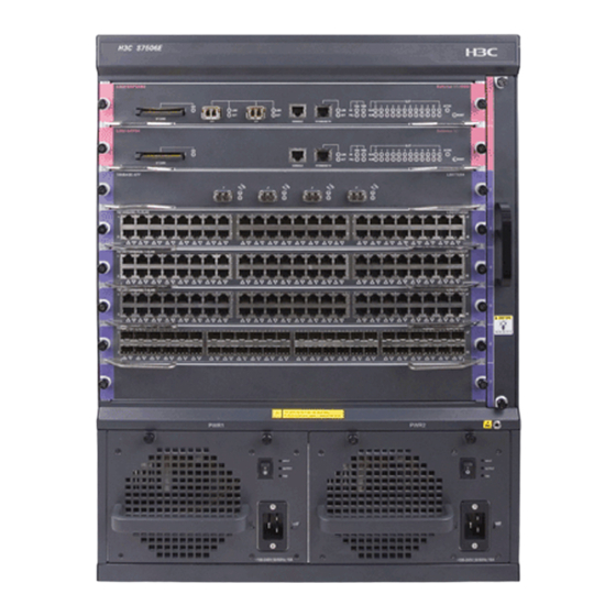
The S7500E Series Ethernet Switches (hereinafter referred to as the S7500E series) are high performance, cost-effective Layer-3 switches with a large capacity. The S7500E series are designed to operate at the core layer of small- and medium-sized networks, the distribution layer of large enterprise networks, and the distribution and access layers of metropolitan area networks (MANs). -
Page 13: Physical Architecture
Physical architecture Chassis The S7500E series consists of a switching and routing processing unit (SRPU) section, line processing unit (LPU) section, power supply module section, and fan tray section. The following uses an S7503E as an example. Figure 2 Front view of the S7503E... -
Page 14: Srpu
Fan tray The S7500E series provide a fan tray for each type of chassis. The location of fan trays varies depending on the chassis types. The fan tray of the S7502E, S7503E-S, S7503E, S7506E-S, S7506E, and S7510E switches is •... - Page 15 The S7506E-V provides two air filters. The one in front of the chassis is installed between the card • section and power supply section, and the one at the back of the chassis is installed at the position corresponding to the front air filter. CAUTION: Clean air filters periodically (at least once every three months) to guarantee adequate ventilation and heat dissipation.
-
Page 16: Preparing For Installation
Tools and equipment • Safety recommendations To avoid possible bodily injury and equipment damage, read the safety recommendations in this chapter carefully before installing an H3C S7500E switch. The recommendations do not cover every possible hazardous condition. General safety recommendations •... -
Page 17: Esd Prevention
The laser inside the optical fiber may hurt your eyes. Examining the installation site The H3C S7500E series can only be used indoors. To ensure that the switch works properly and to prolong its service lifetime, the installation site must meet the following requirements. -
Page 18: Humidity Requirements
Table 2 Temperature requirements Temperature Range Operating temperature 0°C to 45°C (32°F to 113°F) Storage temperature –40°C to +70°C (–40°F to +158°F) CAUTION: If condensation appears on the switch when you move it to a high-temperature environment, dry the switch before powering it on to avoid short circuits. -
Page 19: Emi Requirements
Perform the following steps to satisfy the power supply requirements of the S7500E series: Calculate the total power consumption The total power consumption of an S7500E series switch depends on card type and quantity and fan tray power consumption. If the switch provides PoE power, the total power consumption also depends on PoE power consumption. -
Page 20: Cooling Requirements
Cooling requirements For adequate heat dissipation, plan the installation site according to the airflow of your switch, and adhere to the following requirements: Leave a clearance of at least 10 cm (3.94 in) around the air intake and exhaust vents. •... -
Page 21: Space Requirement
1 m (3.28 ft), and the headroom in the equipment room is no less than 3 m (9.84 ft). Tools and equipment Table 6 lists the tools and equipment that you may use when installing an S7500E series switch. Table 6 Tools and equipment list Category Tool... - Page 22 Category Tool Tools for fiber-optic Lint-free paper and optical fiber microscope cleaning Multimeter, 500 V Megohmmeter for measuring the insulation resistance, error detector, Equipment optical power meter, and earth resistance tester NOTE: Tools and equipment are not supplied with the switch. Prepare them by yourself as needed.
-
Page 23: Installing The Switch
Installing the switch This chapter includes these sections: Installation flow • Inspecting the switch • Installing slide rails and cage nuts to the rack • Installing accessories to the chassis • Mounting the switch to the rack • • Connecting the PGND cable IMPORTANT: Keep the packages of the switch and the components for future use. -
Page 24: Inspecting The Switch
For the slide rails, H3C recommends that you order the H3C Slide Rail Accessories,500mm-800mm (LSTM2KSGD0). Position the chassis of the S7500E series according to their heights. For the specifications of the S7500E • series, see the chapter “Appendix A Hardware specifications.”... - Page 25 Figure 6 Right slide rail 1: Signs 2: Guide rail 3: Installation hole Table 8 Description of signs on the slide rails Sign Meaning Remarks Front end of the left slide rail Mount this end to the front left rack post. Front end of the right slide rail Mount this end to the front right rack post.
- Page 26 Figure 7 Locate the position on the rack for installing the slide rail 1: Middle of the narrower metal area between holes Install six cage nuts on the square holes on each rack post, as shown in Figure Step3 Figure 8 Install a cage nut Align the installation holes on the front end of the slide rail with the cage nuts on the front rack post, and Step4 fix them with screws, as shown in...
- Page 27 Figure 9 Fix the slide rail to the cage nuts with screws Keep the slide rail horizontally and adjust its length until the installation holes on the rear end of the slide Step5 rail touch the cage nuts on the rear rack post. Then fix them with screws. TIP: Fix all installation holes of the slide rail with screws to ensure its weight bearing capacity.
-
Page 28: Installing Cage Nuts For Mounting Brackets
Figure 10 Installed slide rails NOTE: To ensure stability of the rack, install the slide rails to the lowest possible position when installing a single switch on the rack. To install multiple switches on the rack, mount the heaviest switch at the bottom of the rack. -
Page 29: Installing Accessories To The Chassis
Figure 11 Install the cage nuts (S7503E) 1: Cage nut NOTE: When preparing for installation, make sure that the total height of the switches to be installed is no higher than the height of the rack. Installing accessories to the chassis Installing mounting brackets and cable management brackets Before installing the switch to the rack, install the mounting brackets and cable management brackets shipped with the switch. - Page 30 Other models: Install the cable management brackets to the mounting brackets, and then install the • mounting brackets to the chassis. For more information, see “Installing the cable management brackets on other models” and “Installing the mounting brackets.” Installing the cable management brackets on the S7506E-V The S7506E-V has two cable management brackets—the one with a tray is installed at the lower part of the switch, and the one without a tray is installed at the upper part of the switch.
- Page 31 Figure 13 Install the cable management bracket to the left mounting bracket 1: Left mounting bracket 2: Cable management bracket 3: Screw hole for installing the cable management 4: Screw for fixing the cable management bracket to bracket the left mounting bracket Installing the mounting brackets Before installing the switch to the rack, install the mounting brackets to the chassis, as shown in Figure...
-
Page 32: Installing An Air Filter
Installing an air filter Air filters of the S7500E series are optional. If you have ordered air filters, H3C recommends you to install the air filters before mounting the switch to the rack. S7506E-V: An air filter is available at both front and rear of the switch, and can be installed in the •... -
Page 33: Mounting The Switch To The Rack
Figure 16 Install an air filter (S7503E) 1: Fix the fastening strips onto the chassis 2: Push the air filter in between the fastening strips 3: Fasten the captive screws Mounting the switch to the rack Follow these steps to mount the switch to the rack: Face the rear of the chassis towards the front of the rack. -
Page 34: Connecting The Pgnd Cable
Figure 17 Install the chassis to the rack (S7503E) 1: Slide the chassis into the rack 2: Left mounting bracket 3: Right mounting bracket 4: Screws for fixing the mounting brackets to the rack NOTE: If the screw holes on the mounting brackets cannot align with the cage nuts on the rack, check that the bottom edge of the slide rail aligns with the middle of the narrowest metal area between holes and that the cage nuts are installed in the correct holes. -
Page 35: Grounding The Switch Through The Pe Wire Of An Ac Power Supply
Figure 18.). NOTE: The PGND cable provided with the S7500E series is compliant with the NEBS standards. Fasten the grounding screws, which are attached with the dual-hole OT terminals of the PGND cable, Step3 into the grounding holes of the chassis. -
Page 36: Grounding The Switch Through The Rtn Wire Of A Dc Power Supply
CAUTION: Make sure that the AC power supply uses a three-wire cable with a protection wire, and the PE wire of the AC power supply is well grounded at the power distribution room or AC power supply transformer side. In addition, make sure that the PE connector on the switch is well connected to the PE wire of the AC power supply. - Page 37 Figure 20 Ground the switch through the RTN wire of the DC power supply...
-
Page 38: Installing Modules
Installing a transceiver module (optional) • NOTE: No strict order is required for installing modules. H3C recommends you to install the modules needed, and then connect the power cable. IMPORTANT: Keep the packages of the switch and the components properly for future use. -
Page 39: Installing A Card
Figure 21 Attach an ESD-prevent wrist strap (on an S7503E) 1: ESD-preventive wrist strap port (having an ESD sign) Installing a card NOTE: All the switching and routing processing units (SRPUs) and line processing units (LPUs) for the S7500E series are hot swappable, and the installation procedures are similar. Follow these steps to install a card: Wear an ESD-preventive wrist strap, and make sure it has a good skin contact and is well grounded. -
Page 40: Installing A Power Module
5: Fasten the captive screws Installing a power module The S7500E series adopts 1 + 1 power redundancy and supports dual-grid power input. You can select AC or DC power supply as needed. For more information about optional power modules, see the chapter “Appendix B Pluggable module ordering guide.”... -
Page 41: Installing A Power Module
Installing a power module CAUTION: Before installing a power module, make sure that the power module is switched off. • Make sure the power of the power module can satisfy the requirements of the switch. • • When moving the power module, support the bottom of the power module, instead of holding its handle to avoid damaging the power module. -
Page 42: Connecting The Power Cable
Connecting the power cable WARNING! Before connecting the power cable, make sure that the power module that connects to the power cable is switched off. Table 9 Power cable connection for the S7500E series Power input Model PoE support Description... - Page 43 Install a bail latch on the power module. Insert the two ends of the bail latch to the slots on the left of the Step1 power socket. Then pull the bail latch to the left. Take the power cable out of its package, and make sure of the power cable model (both the PSR320-A Step2 and PSR650-A use a 10 A AC power cable).
- Page 44 Figure 25 Connect the PSR1400-A power cable 1: Power switch (O: off; —: on) 2: Power module LED 3: Power cable retainer suite 4: Screw 5: AC power cable Connecting the PSR2800-ACV power cable The PSR2800-ACV is a built-in power module with AC input and DC output. It can provide the switch with both system power and PoE power, which can be controlled through separate power switches.
- Page 45 Figure 26 PSR2800-ACV panel 1: Captive screw 2: System power socket 3: Power cable retainer suite 4: System power switch (O: off; —: on) 5: Power module status LED 6: PoE power socket 7: PoE power switch (O: off. —: on) 8: Power module handle Connecting the PSR6000-ACV power cable The PSR6000-ACV is a built-in power module with AC input and DC output.
- Page 46 Figure 27 PSR6000-ACV panel 1: Captive screw 2: PoE power switch (O: off; —: on) 3: Power module status LED 4: Fastening screw holes for the power cable retainer suite 5: System power socket 6: System power switch (O: off; —: on) 7: Power module handle 8: PoE power sockets The PSR6000-ACV is shipped with a power cable retainer suite.
- Page 47 Figure 28 Attach the power cable retainer suite 1: Fastening screw holes for left and right parts of the 2: Power cable plug retainer suite 3: Fastening screw holes for the retainer suite and 4: Fastening screws for left and right parts of the power module retainer suite After attaching the power cable retainer suite to the power cable, connect the power cable to the...
- Page 48 Figure 29 Connect the AC power cable to the PSR6000-ACV Connecting the PSR320-D/PSR650-D power cable Follow these steps to connect the PSR320-D/PSR650-D power cable: Remove the protection cover from the power module. Step1 Loosen the captive screw on the wiring terminal with a Phillips screwdriver. Step2 Connect the end of the blue DC power cable marked with –...
- Page 49 Figure 30 Connect the PSR320-D/PSR650-D power cable 1: Protection cover 2: Screws 3: DC wiring terminals 4: Grounding sign Connecting the PSR1400-D power cable Follow these steps to connect the PSR1400-D power cable: Loosen the captive screws on the protection cover with a Phillips screwdriver and remove the protection Step1 cover.
-
Page 50: Setting Up A Poe System (Optional)
(PDs) from Ethernet interfaces through twisted pair cables. Commonly used PDs include: IP telephones, wireless LAN access points (APs), and web cameras. To set up a PoE system for the S7500E series, the following requirements should be met: Switch and card models supporting PoE •... - Page 51 Table 10 Cards supporting PoE Number of Card model POE-capable PoE DIMM PoE type ports LSQ1GV48SD0 No PoE DIMM needed Type1, Type2 LSQ1CGV24PSC0 LSQ1GV24PSC0 24-port PoE DIMM (LSQM1POEDIMMS0) LSQ1GV24PSA0 LSQ1FV48SA0 Type 1 LSQ1GV48SA0 PoE master/subordinate DIMM (LSBM1POEDIMMH) LSQ1GV48SC0 LSQ1GV40PSC0 NOTE: The following PoE types are available: Type 1—Power delivered by a single port: 0 to 15.4 W;...
-
Page 52: Installing A Poe Dimm
Separate Power module PoE maximum power output PoE power Power cable connection model cable 1200 W (110 One-line input 1800 W (220 2400 W (110 Connecting the PSR6000-ACV power PSR6000-ACV Two-line input cable 3600 W (220 3600 W (110 Three-line input 5300 W (220 CAUTION: If you do not use the PoE function, check that the PoE power switch on the power module is off. - Page 53 Wear an ESD-preventive wrist strap and make sure it has a good skin contact and is well grounded. For Step1 more information, see “Attaching an ESD-preventive wrist strap.” Make sure the card is sturdy. Then find the PoE DIMM slot (there is a master silkscreen on the PCB under Step2 the slot) on the PCB.
- Page 54 CAUTION: Determine the PoE master DIMM and PoE subordinate DIMM before installation. For how to distinguish • them, see Figure Plug the master DIMM into the master DIMM slot (there is a master silkscreen on the PCB under the slot), •...
-
Page 55: Connecting An External Poe Power Supply
To supply PoE power to S7502E or S7503E-S, a PoE power cable is required to connect the external PoE power supply to the PoE input on the chassis rear panel. You can use an H3C RPS800-A or other DC power supplies that can satisfy PoE input requirements: voltage range –46 V to –57 V (–52 V to –57 V for type 2) and maximum current 40 A, as the external PoE power supply. -
Page 56: Installing A Cf Card To The Srpu (Optional)
NOTE: RPS800-A User Manual For more information about RPS800-A, see the Connecting a user-supplied power cable to the PoE input on the chassis rear panel Follow these steps to connect a user-supplied power cable to the PoE input on the chassis rear panel: Remove the blank panel covering the PoE port of the switch. -
Page 57: Installing A Transceiver Module (Optional)
When the switch is powered on, check the running status of the CF card. Step3 NOTE: To check the CF card status, check the CFS LED on the SRPU of the switch. If the LED is on, the CF card •... -
Page 58: Connecting An Sfp+ Cable
Figure 37 Install an XFP/SFP+/SFP module NOTE: When inserting the module to the switch, you can use your finger gently push against the front face of • the module into the slot, rather than inserting it by holding both sides of the module. Press down the XFP/SFP+/SFP module a little against the upward force of the bottom spring tab so that •... -
Page 59: Setting Up An Irf Virtual Device
Connecting the physical IRF ports • • Accessing the IRF virtual device to verify the configuration NOTE: H3C S7500E Series Ethernet Switches IRF Configuration Guide. For more information about IRF, see the Prerequisites You are familiar with IRF. IRF virtual device setup flowchart... -
Page 60: Planning Irf Virtual Device Setup
Planning the IRF network Plan the IRF network and identify the role, member ID, physical IRF ports of each member switch. For IRF configuration and management, see the H3C S7500E Series Ethernet Switches IRF Configuration Guide. Identifying the master switch Determine which switch you want to use as the master for managing all member switches in the IRF virtual device. -
Page 61: Installing Irf Member Switches
Determine which 10-GE ports to use for IRF connection depending on the bandwidth and reliability requirements. The S7500E series switches support link aggregation and cross-card aggregation for IRF ports. You can bind up to eight physical ports to one IRF port. -
Page 62: Accessing The Irf Virtual Device To Verify The Configuration
Create a Layer 3 interface, assign it an IP address, and make sure that the IRF virtual device and the Step2 remote network management station can reach each other. Use Telnet or SNMP to access the IRF virtual device from the network management station. (See the H3C Step3 S7500E Series Ethernet Switches Fundamentals Configuration Guides.) Check that you can manage all member switches as if they were one node. - Page 63 To avoid IP address collision and network problems, configure the multi-active detection (MAD) • mechanism to detect the presence of multiple identical IRF virtual devices and handle collisions. For H3C S7500E Series Ethernet Switches IRF more information about MAD detection, see the Configuration Guide.
-
Page 64: Connecting Your Switch To The Network
NOTE: For more information about login methods, see the Fundamentals Configuration Guide in the S7500E Series Ethernet Switches Configuration Guide User interfaces supported by the switch The switch supports the following user interfaces. AUX user interface: Manages and monitors users that log in through the console port. -
Page 65: Console Cable
NOTE: On an S7500E switch, the maximum number of AUX users allowed to log in at the same time depends • on the number of switching and routing processing units (SRPUs), and is two on an S7500E switch installed with two SRPUs. After the switches form an IRF virtual device, the maximum number of AUX users allowed to log in to the •... -
Page 66: Setting Up The Configuration Environment
Table 15 Preparations before the first login Item Description An 8-core cable, with an RJ-45 connector at one end and a DB-9 female connector at the Console cable other Configuration A PC with a serial port. terminal Setting up the configuration environment Follow these steps to connect the local terminal (a PC in this example) to the console port of the switch through a console cable, as shown in Figure... -
Page 67: Setting Up The Hyperterminal Connection And Setting The Terminal Parameters
Setting up the HyperTerminal connection and setting the terminal parameters To log in to the switch from the local terminal, run the HyperTerminal software on the local terminal. The following example takes the Windows XP HyperTerminal as an example, and describes how to run it on the PC. - Page 68 Figure 43 Select a serial port for the new HyperTerminal connection After selecting a serial port, click OK. Then, the COM1 Properties window as shown in Figure 44 • appears. On the window, set Bits per second to 9600, Data bits to 8, Parity to None, Stop bits to 1, and Flow control to None.
- Page 69 Figure 45 The HyperTerminal connection is set up successfully Setting the attributes for the new HyperTerminal Select File > Properties on the HyperTerminal window, and the aaa Properties window as shown in Figure 46 appears. Click the Settings tab. Select VT100 from the Emulation drop-down list, and then click...
-
Page 70: Checks Before Powering On The Switch
Figure 46 Select the emulation terminal on the aaa Properties window Checks before powering on the switch Before powering on the switch, check the following items: • The switch has been steadily mounted. All the cards have been correctly installed. •... - Page 71 NOTE: The output may vary by software version. Starting..RAMLine..OK System is booting....************************************************************************ BOOTROM, Version 3.01 ************************************************************************ Creation Date : Aug 26 2010 CPU Type : BCM1125H CPU L1 Cache : 32KB CPU Clock Speed : 600MHz Memory Type : DDR SDRAM Memory Size : 512MB...
-
Page 72: Initially Configuring The Switch
NOTE: For more information about login methods, see the Fundamentals Configuration Guide in the S7500E Series Ethernet Switches Configuration Guide Configuring the basic access function When the switch with the default settings accesses the network, it can perform basic data transmission. -
Page 73: Configuration Example
Table 17 Basic access function configurations Function Description IP addresses Allows you to remotely manage the switch and use the switch in a network. Static routing Allows the switch to implement routing. VLAN Divides the network into multiple VLANs, and improves data security. MSTP Avoids loops in a network using dual uplinks to provide redundancy. -
Page 74: Displaying The Network Configuration
[Sysname] stp instance 1 root primary # Enable MSTP globally. [Sysname] stp enable NOTE: H3C S7500E Series For more information about the access function configuration, see related sections in Ethernet Switches Configuration Guide Displaying the network configuration You can use the following commands to check the software version and configuration information of your switch, and determine whether the software version and configuration of your switch are correct. -
Page 75: Connecting The Switch To The Network
Connecting your switch to the network through twisted pair cables The 10/100Base-TX and 1000Base-T ports of the H3C S7500E series switches use RJ-45 connectors and support MDI/MDI-X auto-sensing. Use category-5 or better twisted pair cables to connect the Ethernet ports of your switch to the network. - Page 76 When the switch is connected to the network, you can use the ping or tracert command check the • connectivity between the switch and the network. For more information about the two commands, see H3C S7500E Series Ethernet Switches Command Reference • For more information about the optical fibers, see the chapter “Appendix D Cables.”...
-
Page 77: Hardware Management And Maintenance
H3C Comware Platform Software Comware Software, Version 5.20, Release 6606 Copyright (c) 2004-2010 Hangzhou H3C Tech. Co., Ltd. All rights reserved. H3C S7503E uptime is 0 week, 0 day, 6 hours, 57 minutes MPU(M) 0: Uptime is 0 weeks,0 days,6 hours,57 minutes... - Page 78 CPLD 1 Version: CPLD 2 Version: Release Version: H3C S7503E-6606 Patch Version None MPU(S) 1: Uptime is 0 weeks,0 days,1 hours,23 minutes H3C S7503E MPU(S) with 1 BCM1125H Processor BOARD TYPE: LSQ1SRP2XB DRAM: 512M bytes FLASH: 64M bytes NVRAM: 512K bytes PCB 1 Version: VER.B...
- Page 79 Comware Software, Version 5.20, Release (Comware), platform version (Version 5.20), and product 6606 release version (Release 6606) H3C S7503E uptime is 0 week, 0 day, 6 Displays how long the switch has been running since the last hours, 57 minutes reboot...
-
Page 80: Displaying Switch Running Information
Field Description FLASH Flash size of the card NVRAM Nonvolatile random-access memory (NVRAM) size of the card PCB 1 Version Version of PCB 1 on the card Bootrom Version Boot ROM version of the card Complex programmable logical device (CPLD) 1 version of CPLD 1 Version the card Release Version... - Page 81 LSQ1SRP2XB Master S7500E-6606 None LSQ1SRP2XB Slave S7500E-6606 None LSQ1GV48SA Normal S7500E-6606 None LSQ1NAT24SC Normal S7500E-6606 None LSQ1PT4PSC Normal S7500E-6606 None SRP2XBSLAVE Normal S7500E-6606 None SRP2XBSLAVE Normal S7500E-6606 None Slot 0 info: Status Master Type LSQ1SRP2XB Software Ver S7500E-6606 PCB 1 Ver VER.B PCB 2 Ver VER.B...
- Page 82 FPGA Ver Bootware Ver CPLD 1 Ver Chip Learning Mode: Slot 4 info: Status Normal Type LSQ1PT4PSC Software Ver S7500E-6606 PCB 1 Ver VER.B FPGA Ver BootRom Ver CPLD 1 Ver CPLD 2 Ver Chip Learning Mode: Slot 5 info: Status Normal Type...
-
Page 83: Displaying Electronic Card Label Information
MAC address, and vendor name. You can use this information to verify that the card is genuine. <Sysname> display device manuinfo Slot 0: DEVICE_NAME : LSQM1SRP2XB0 DEVICE_SERIAL_NUMBER : 210231A73JB098000078 MAC_ADDRESS : 0023-895F-958B MANUFACTURING_DATE : 2009-8-24 VENDOR_NAME : H3C Slot 1: DEVICE_NAME : LSQM1SRP2XB0 DEVICE_SERIAL_NUMBER : 210231A73JB098000070 MAC_ADDRESS : 0023-895F-954F... - Page 84 MANUFACTURING_DATE : 2009-8-24 VENDOR_NAME : H3C Slot 2: DEVICE_NAME : LSQM1GV48SA0 DEVICE_SERIAL_NUMBER : 210231A76HB095000082 MAC_ADDRESS : NONE MANUFACTURING_DATE : 2009-10-15 VENDOR_NAME : H3C Slot 3: DEVICE_NAME : LSQM1NAT24SC0 DEVICE_SERIAL_NUMBER : 210231A0EAX103000002 MAC_ADDRESS : NONE MANUFACTURING_DATE : 2010-03-11 VENDOR_NAME : H3C...
-
Page 85: Displaying Card Cpu Usage Statistics
Displaying card CPU usage statistics Use the display cpu-usage command to display card CPU usage statistics: <Sysname> display cpu-usage Slot 0 CPU usage: 2% in last 5 seconds 1% in last 1 minute 1% in last 5 minutes Slot 1 CPU usage: 1% in last 5 seconds 1% in last 1 minute 1% in last 5 minutes... -
Page 86: Displaying Card Memory Usage Statistics
Field Description 1% in last 5 minutes The average CPU usage for the last five minutes. Displaying card memory usage statistics Use the display memory command to display the memory usage of the active SRPU: <Sysname> display memory System Total Memory(bytes): 435927120 Total Used Memory(bytes): 100618856 Used Rate: 23% Use the display memory slot slot-number command to display the memory usage of a card:... -
Page 87: Displaying The Operating Status Of Fans
Displaying the operating status of fans Use the display fan command to display the operating status of fans: <Sysname> display fan 1 State: Normal Table 24 Output description Field Remarks Fan number Fan status: • Normal—The fan is correctly operating. State •... -
Page 88: Configuring The Temperature Thresholds For A Card
Configuring the temperature thresholds for a card The switch sends traps when the temperature of a card crosses the lower or upper temperature threshold. You can change the temperature threshold settings for a card as needed so you can remove the alarm condition in time. -
Page 89: Enabling Active/Standby Mode For The Network Ports On Srpus
If the output includes “Media type is not sure, Port hardware type is No connector,” the port is an • SFP fiber port. For example, the following output shows that GigabitEthernet 2/0/1 is an SFP port. [Sysname] display interface GigabitEthernet 2/0/1 GigabitEthernet2/0/1 current state: DOWN IP Packet Frame Type: PKTFMT_ETHNT_2, Hardware Address: 0000-fc00-7506 Description: GigabitEthernet2/0/1 Interface... -
Page 90: Displaying Transceiver Module And Alarming Information
on the previous standby SRPU comes up to take over. You can connect the Ethernet network ports on the two SRPUs to upstream devices to increase availability. NOTE: If one or two LSQ1SRP2XB or LSQ1SRP12GB SRPUs are used, the switch creates one virtual LPU slot for each SRPU slot, and the LPU slot numbers are higher than the largest physical LPU slot number. -
Page 91: Configuring A Software Exception Handling Method
NOTE: The display transceiver diagnosis interface command cannot display information for some transceiver modules. NOTE: H3C Mid-Range Series Ethernet Switches For more information about transceiver modules, see • Pluggable Modules Manual For more information about transceiver-related commands, see the command references for the S7500E •... -
Page 92: Displaying The Exception Handling Method
NOTE: If two SRPUs are used, the reboot of the active SRPU causes an active/standby switchover. • If one SRPU is used, the reboot of the active SRPU causes the entire switch to reboot. • An LPU always automatically reboots when it detects a software exception. •... -
Page 93: Displaying The Basic Irf Settings Of Irf Member Switches
Field Description Priority Priority of a member switch CPU-MAC Bridge MAC address of the CPU of the switch Description of the member switch (----- is displayed if no description is configured). If the description of the member switch exceeds one line, three dots (…) are Description displayed at the end of the line, and the rest information is not displayed. -
Page 94: Displaying Irf Topology Information
Field Description The member ID re-assigned to the switch. This setting takes effect at reboot. New-ID This field is available only in IRF mode. Ports bound to IRF port 1. To bring up IRF port 1, you must bind at least one IRF-Port1 physical port to it. -
Page 95: Rebooting A Card Or The Switch
After the switch reboots, you must re-specify the startup configuration file for the next reboot. For more information about the save commands, see the fundamentals configuration guide for the H3C •... - Page 96 To do… Use the command… Remarks Available in user view. Reboot the switch or a card other than the standby SRPU at once (in reboot [ slot slot-number ] If no slot is specified, the command standalone mode) reboots the entire switch. Reboot the standby SRPU (in slave restart Available in system view.
-
Page 97: Troubleshooting
Troubleshooting This chapter describes how to troubleshoot your S7500E switch: Troubleshooting methods • Troubleshooting the system • Troubleshooting the power supply system • • Troubleshooting the fans Troubleshooting the SRPUs • Troubleshooting the LPUs • Troubleshooting interfaces • Troubleshooting CF cards •... -
Page 98: Troubleshooting The System
Troubleshooting the system Troubleshooting on startup After you power on the switch, if the switch operates properly, the startup information appears on the console terminal. If the console terminal displays nothing or garbled characters, use the following methods to troubleshoot the switch. No display on the terminal If the console terminal displays nothing after you power on the switch, check the following items: The power supply system works properly. -
Page 99: Troubleshooting The Fans
NOTE: For more information about the PWR LEDs on an SRPU and the LEDs on a power module, see the • chapter “Appendix C LEDs.” After the power supply to the power module is turned off, it is normal that the LEDs stay on for a period •... -
Page 100: Troubleshooting The Srpus
Troubleshooting the SRPUs The status LEDs on the SRPU show the status of a card in the corresponding slot. According to the slot number of an SRPU, you can check the corresponding LEDs for the SRPU. When the SRPU works properly, the RUN LED blinks, and the ALM LED is off. When the RUN LED is off, the SRPU fails. -
Page 101: Troubleshooting Cf Cards
NOTE: A management Ethernet interface, SFP+ interface, or XFP interface each has two LEDs, LINK and ACT. The LED mentioned in this section for such an interface refers to the LINK LED. Each interface of any other type has only one LED. If the LED of an interface connected to the network is off, the interface or the connecting cable may fail. -
Page 102: Troubleshooting The Poe System
Software version • Maintenance agreement or warranty card • Brief problem description • • Brief explanation of the troubleshooting measures that have been taken You can contact the customer service through the H3C website, or email. Website: http://www.h3c.com E-mail: customer_service@h3c.com... -
Page 103: Replacement Procedures
Replacement procedures All components of the S7500E series switches are hot swappable. You can replace any of them when the switch is running. CAUTION: When replacing pluggable modules when the switch is running, notice safety with electricity. This chapter includes these sections: Replacing a power module •... - Page 104 CAUTION: Power module replacement involves removal and installation of power modules and power cables. Strictly follow the procedures shown in Figure 48 Figure 49 to replace a power module to avoid device or bodily injury. Figure 48 Power module removal flow Figure 49 Power module installation flow WARNING! An AC power module and a DC power module cannot be installed on the same S7500E switch, and...
-
Page 105: Replacing A Card
CAUTION: • The power module of the S7500E series is heavy. When pulling the power module out of the slot, support the bottom of the power module with one hand and hold the handle of the power module with the other. -
Page 106: Replacing A Fan Tray
The fan tray handle of the S7506E-V adopts a snap-in design. To remove or install a fan tray, rotate • the handle out first, as shown in Figure The fan tray handle of the other models of the S7500E series is fixed to the fan tray, as shown in • Figure Replacing an S7506E-V fan tray... - Page 107 Wear an ESD-preventive wrist strap and make sure it has a good skin contact and is well grounded. For Step2 more information, see the chapter “Installing modules.” Use a screwdriver to remove the captive screw on the fan tray, as shown in callout 1 on Figure Step3 Press the left side of the fan tray handle to rotate it out from the slot, as shown in a callout 2 on...
-
Page 108: Replacing The Fan Tray Of Other Models
Check the FAN LEDs on the SRPU of the switch. If the OK LED is on, the fan tray is installed successfully. Step4 For more information about the FAN LEDs, see the chapter “Appendix C LEDs.” NOTE: Make sure the fan tray handle has been pushed in to the slot after installation. •... -
Page 109: Replacing An Air Filter
The S7506E-V has two air filters on its front and rear panels. For how replace the air filters, see • “Replacing air filters on an S7506E-V.” Other models of the S7500E series has only one air filter. For how to replace it, see “Replacing an • air filter for the other models.”... -
Page 110: Replacing An Air Filter For The Other Models
Figure 54 Replace an air filter for S7506E-V 1: Loosen the captive screws on the air filters with a screw driver 2: Remove the air filters from the chassis Replacing an air filter for the other models Follow these steps to replace an air filter: Loosen the captive screw on the air filter, as shown in callout 1 on Figure Step1... -
Page 111: Replacing A Cf Card
Figure 55 Remove an air filter for the other models 1: Loosen the captive screw on the air filter 2: Pull the air filter out of the chassis Replacing a CF card NOTE: • Before replacing a CF card, execute the umount command to unmount the CF card to ensure that the file system on the CF card is not damaged when you remove the CF card. -
Page 112: Replacing A Transceiver Module
Figure 56 Replace the CF card 1: Press the eject button of the CF card 2: The reader ejects the card part way out of the slot 3: CF card ejector button 4: CF card status LED CAUTION: Do not remove the CF card when the switch is booting or the CF card LED is blinking. Otherwise, the file system on the hardware or the CF card may be damaged. -
Page 113: Replacing An Sfp+ Cable
WARNING! Do not stare at the fibers to avoid hurting your eyes. • When installing or removing an XFP/SFP+/SFP module, do not touch the golden finger of the module. • Figure 57 Remove an XFP/SFP+/SFP module Replacing an SFP+ cable Follow these steps to replace an SFP+ cable: Wear an ESD-preventive wrist strap and make sure it has a good skin contact and is well grounded. - Page 114 Install a new PoE DIMM. For the installation procedures, see the chapter “Installing modules.” Step6 Figure 58 Install a PoE DIMM 1: Pull the white clips on the two sides of the DIMM outward 2: Pull the PoE DIMM out along the guide rails...
-
Page 115: Appendix A Hardware Specifications
Appendix A Hardware specifications Weights and dimensions Table 29 Chassis weights and dimensions Dimensions Model Weight Height Width Depth 175 mm (6.89 in) (4 436 mm (17.17 420 mm (16.54 S7502E < 15 kg (33.07 lb) 175 mm (6.89 in) (4 436 mm (17.17 420 mm (16.54 S7503E-S... - Page 116 Dimensions Card model Weight Height Width Depth LSQ1SRPA0 (Salience 2.61 kg (5.75 399 mm (15.71 352 mm (13.86 45 mm (1.77 in) VI-Smart) 399 mm (15.71 352 mm (13.86 LSQ1SRPB0 (Salience VI) 3.6 kg (7.94 lb) 45 mm (1.77 in) 3.56 kg (7.85 399 mm (15.71 352 mm (13.86...
- Page 117 Dimensions Card model Weight Height Width Depth 2.95 kg (6.50 399 mm (15.71 352 mm (13.86 LSQ1TGX2SC0 40 mm (1.57 in) 399 mm (15.71 352 mm (13.86 LSQ1GV24PSC0 2.8 kg (6.17 lb) 40 mm (1.57 in) 2.95 kg (6.50 399 mm (15.71 352 mm (13.86 LSQ1P24XGSC0 40 mm (1.57 in)
- Page 118 352 mm (13.86 LSQ1TGX4EB0 40 mm (1.57 in) NOTE: The dimensions of the cards of the S7500E series are expressed in H, W, and D. The following describes them in detail: • H—Height of the front panel of the card W—Width of the front panel of the card...
-
Page 119: Module Power Consumption And Total Power Consumption
The PoE power consumption is the sum of the power consumption of all PDs connected to the switch. • Card power consumption The power consumption of the cards of the S7500E series depends on the card model and state. Table shows the power consumption for different card models. -
Page 120: Card Power Consumption
PoE power consumption The maximum PoE power consumption for the S7500E series depends on the type and number of PoE cards, PoE power supply mode supported by each PoE card, and the number of ports that support PoE. For example, if an S7503E switch has one LSQ1GV48SD0 (LSQM1GV48SD0), two LSQ1GV24PSC (LSQM1GV24PSC0), and the SRPU does not support PoE, the maximum PoE power consumption of the switch is 48 ×... - Page 121 Minimum static power Maximum dynamic power Model consumption consumption LSQ1GV48SA0 60 W 80 W LSQ1GP12SC0 26 W 35 W LSQ1GP24SC0 38 W 55 W LSQ1GP48SC0 43 W 85 W LSQ1GP24TSC0 25 W 45 W LSQ1GT24SC0 42 W 50 W LSQ1GV48SC0 60 W 90 W LSQ1TGS8SC0...
-
Page 122: Fan Tray Power Consumption
80%. Heat dissipation/hour of the switch is 0.9 × (total power consumption of the cards plus power consumption of the fan tray)/0.8 × 3.4121. NOTE: For the power consumption of the cards and fan trays of the S7500E series switches, see “Module •... -
Page 123: Noise
Noise The S7500E series switches adopt different types of fan trays. The S7503E-S adopts fans with a fixed speed (the fan speed does not change with the heat dissipation volume), so the sound pressure level of the switch is fixed. The other models adopt fans with the automatic speed adjustment function, so the sound pressure levels are different when the fan speeds are different. -
Page 124: Appendix B Pluggable Module Ordering Guide
SRPU overview The switching and routing processing unit (SRPU) is the core of the control management plane and the switch fabric for the S7500E series. The S7500E series supports the following SRPU models. NOTE: The model of a card is LSQM-prefixed on the card package and LSQ-prefixed on the card panel. For example, LSQ1MPUA0 and LSQM1MPUA0 identify the same card. -
Page 125: Srpu Ordering Guide
SRPU ordering guide Table 38 shows the models and number of SRPUs that an S7500E chassis supports. NOTE: The S7500E series except the S7503E-S supports two SRPUs, which must be of the same model. • • Table 38, “ ” indicates compatible, and “—” indicates incompatible. -
Page 126: Lpu
— (Salience VI-10GE) LPU overview The S7500E series supports various LPUs. The number and type of interfaces provided by an LPU depend on the LPU type. NOTE: The model of a card is LSQM-prefixed on the card package and LSQ-prefixed on the card panel. For example, LSQ1FP48SA0 and LSQM1FP48SA0 identify the same card. - Page 127 Number Available Conne Interface Description transceiver ctor transmission rate interfaces modules • Gigabit SFP module 1000/100 Mbps 16-port Gigabit optical • 100-Mbps LSQ1GP24 Ethernet interface (SFP, LC) SFP module TSA0 + 8-port Gigabit combo 10/100/1000 interface card RJ-45 Mbps, — half/full-duplex 10/100/1000 RJ-45...
- Page 128 Number Available Conne Interface Description transceiver ctor transmission rate interfaces modules • 10-Gigabit SFP+ LSQ1TGS8 8-port 10-Gigabit optical module 10 Gbps SFP+ interface card • 10-Gigabit SFP+ cable • 10-Gigabit SFP+ LSQ1TGS1 16-port 10-Gigabit optical module 10 Gbps 6SC0 SFP+ interface card •...
- Page 129 Number Available Conne Interface Description transceiver ctor transmission rate interfaces modules 1000 Mbps EPON module 8-port Gigabit passive optical interface (EPON OLT • Gigabit SFP LSQ1PT8PS SFP, SC) +8-port Gigabit module 1000/100 Mbps optical interface (SFP, LC) • 100-Mbps card SFP module 1000 Mbps EPON module...
- Page 130 Number Available Conne Interface Description transceiver ctor transmission rate interfaces modules • Gigabit SFP 48-port Gigabit optical module LSQ1GP48 Ethernet interface card (SFP, 1000/100 Mbps • 100-Mbps SFP module 48-port Gigabit electrical 10/100/1000 LSQ1GV48 Ethernet interface card RJ-45 Mbps, — (RJ-45)-PoE Plus half/full-duplex 2-port 10-Gigabit optical...
-
Page 131: Lpu Ordering Guide
LPU ordering guide The S7500E series supports various LPUs. These LPUs apply to all the S7500E switches. Order and combine the LPUs according to your requirements for interface types and interface • quantity in the network. For more information about the LPUs, see Table •... -
Page 132: Power Module Ordering Guide
Make sure that the total maximum output power of the ordered power modules is greater than the • overall power consumption. H3C recommends that you reserve 20% of the maximum output power. If the switch is expected to supply power for attached devices through PoE, order a power module •... -
Page 133: Fan Tray
Fan tray ordering guide The fans trays are shipped with the S7500E series switches, and have been installed in the S7500E switches. If the fan tray of a switch fails, order a compatible fan tray to replace the failed one. -
Page 134: Air Filter
Different S7500E switches support different air filters. Order air filters compatible with your switch. PoE DIMM PoE DIMM overview The S7500E series switch support various PoE LPUs. To supply power through PoE, you must install a PoE dual-in-line memory (DIMM) module on the PoE •... -
Page 135: Cf Card
Storage medium-CompactFlash car-512MB 512 MB CF-1G Storage medium-CG-1G 1 GB Transceiver modules Transceiver module overview The S7500E series switch supports the following transceiver modules: 10-Gigabit XFP modules listed in Table 45 • 10-Gigabit SFP+ modules listed in Table 46 •... - Page 136 Gigabit SFP modules listed in Table 48 • • 100-Mbps SFP modules listed in Table 49 EPON modules listed in Table 50 • Table 45 XFP module specifications Central Maximum 10-Gigabit XFP module Connector Cable specifications wavelength transmission distance 50/125 μm XFP-SX-MM850 850nm 300 m (984.25 ft)
- Page 137 Table 48 Gigabit SFP module specifications Maximum Central Gigabit SFP module Connector Cable specifications transmission wavelength distance 50/125 μm multimode 550 m (1804.46 ft) fiber SFP-GE-SX-MM850-A 850nm 62.5/125 μm 275 m (902.23 ft) multimode fiber 9/125 μm single-mode SFP-GE-LX-SM1310-A 1310nm 10 km (6.21 miles) fiber 9/125 μm single-mode...
-
Page 138: Transceiver Module Ordering Guide
9/125 μm single-mode fiber miles) RX: 1310nm Transceiver module ordering guide Some SRPUs and LPUs of the S7500E series switches support transceiver modules. For more information, Table 37 Table 39. You can order transceiver modules according to the transceiver modules available on the interfaces and actual service requirements. -
Page 139: Ac Power Cable Ordering Guide
AC power cable ordering guide For the power modules PSR320-A and PSR650-A, select 10-A AC power cables. For the connector • types of different countries or regions, see Table For the power modules PSR1400-A, PSR2800-ACV, and PSR6000-ACV, select 16-A AC power •... - Page 140 Holland, Denmark, Sweden, Finland, 04041056 (3 Indonesia, Turkey, F type Norway, Germany, India m, i.e., 9.8 ft) Russia, and CIS France, Austria, Belgium, and Italy Connector outline Power cable outline Connector outline Countries or regions where the type of Countries or Other countries or Connector power cables conforms...
- Page 141 04040889 (3 D type Hong Kong South Africa m, i.e., 9.8 ft) Connector outline Power cable outline Connector outline Countries or regions where the type of Countries or Other countries or Connector power cables conforms regions seldom Code (Length) regions using this type type to local safety using this type of...
- Page 142 04041120 (3 L type Italy m, i.e., 9.8 ft) Connector outline Power cable outline Connector outline Table 52 16A AC power cables used in different countries or regions Countries or regions where the type of Countries or Other countries or Connector power cables regions seldom...
- Page 143 Countries or regions Countries or where the type of Other countries or Connector power cables regions seldom Code (Length) regions using this type of type conforms to local using this type of power cables safety regulations and power cables can be used legally Holland, Denmark, Sweden, Finland, 0404A061 (3...
- Page 144 Countries or regions Countries or where the type of Other countries or Connector power cables regions seldom Code (Length) regions using this type of type conforms to local using this type of power cables safety regulations and power cables can be used legally 0404A01A (3 I type Australia...
-
Page 145: Appendix C Leds
Appendix C LEDs The S7500E series switches provide various LEDs for you to check the status of SRPUs, LPUs, and power modules. Table 53 shows the supported LEDs. NOTE: The S7500E series switches support various SRPU and LPU models. The type and quantity of LEDs vary by SRPU and LPU models. -
Page 146: Srpu Leds
SRPU LEDs Figure 59 LEDs on an LSQ1SRP2XB0 1: CF card status LED 2: XFP interface status LEDs 3: Management Ethernet interface status LEDs 4: Power and fan status LEDs 5: Card status LEDs 6: SRPU active/standby status LED Management Ethernet interface status LEDs The SRPU provides two management Ethernet interface status LEDs—LINK and ACT—to indicate the link status and data forwarding status of the management Ethernet interface. - Page 147 Table 56 Description of PWR LEDs with numbers LEDs Description FAIL The corresponding power module is working properly. The corresponding power module has no output power. (The cause can be: the power module is faulty or not switched on; a power cable connection problem occurs;...
- Page 148 NOTE: A quick blinking RUN LED indicates that the card is in the process of startup rather than operating properly. The ALM LED will be on for a period of time when the system starts up. SRPU active/standby status LED (ACTIVE) The SRPUs provide the active/standby status LED (ACTIVE) to indicate the status—active or standby—of the SRPUs.
- Page 149 Table 62 Combo port status LED description LED status Description The combo port is receiving or Blinking sending data. Combo port status LED A link is present. No link is present. NOTE: • For the SFP interface and the RJ-45 Ethernet interface of a combo port, only one interface can be active at a time.
-
Page 150: Lpu Leds
LPU LEDs Figure 60 LEDs on an LSQ1T24XGSC0 1: RJ-45 Ethernet interface status LED 2: XFP interface status LEDs RJ-45 Ethernet interface status LED The LPUs provide RJ-45 Ethernet interface status LEDs to indicate the link status and data receiving/forwarding status of the corresponding Ethernet interfaces. Table 65 RJ-45 Ethernet interface status LED description LED status Description... - Page 151 Table 67 SFP interface status LED description LED status Description The SFP interface is receiving or Blinking sending data. SFP interface status LED A link is present. No link is present. SFP+ interface status LEDs The LPUs provide SFP+ interface status LEDs to indicate the link status and data receiving/forwarding status of the corresponding SFP+ interface.
-
Page 152: Power Module Leds
For more information about ONU, see the Configuration Guide Power module LEDs The S7500E series switches support various power module models. Each power module provides a LED to indicate the operating status of the power module. The power module LEDs vary with power module models. - Page 153 Table 72 PSR650-A/PSR650-D power module status LED description Status Meaning Analysis The power module is Green — working properly. This status occurs in the following cases: • The power module generates an alarm due to input The power module is under-voltage, output short-circuit, output over-current, working abnormally.
- Page 154 Status Meaning Analysis The fans are working Green — properly. This status occurs in the following cases: The fans are working • A fan failure occurs. abnormally. • The power module is not switched on. This status occurs in the following cases: •...
- Page 155 Status Meaning Analysis The fans are working Green — properly. The fans are working A fan failure occurs. abnormally. This status occurs in the following cases: • The power module is faulty. • The fans do not work. A power cable connection problem occurs. •...
- Page 156 Status Meaning Analysis The power is output Green — properly. This status occurs in the following cases: • The power module generates an alarm due to A power output problem input under-voltage, output short-circuit, output occurs. over-current, output over-voltage, or over temperature, and enters the protection state.
- Page 157 PSR6000-ACV power module status LEDs The PSR6000-ACV power module provides eight red-green status LEDs—system power input LED (SYS IN), system power output LED (SYS OUT), fan LED (SYS FAN), power input LED (PoE IN1, PoE IN2, and PoE IN3), power output LED (PoE OUTPUT), and PoE fan LED (PoE FAN). Table 76 PSR6000-ACV power module status LED description Status Meaning...
- Page 158 Status Meaning Analysis The PoE power (PoE1) is Green — input properly. A power input problem The input voltage of PoE1 is not in the rated voltage occurs to PoE1. range. PoE IN1 This status occurs in the following cases: •...
- Page 159 Status Meaning Analysis The PoE fans are working Green — properly. This status occurs in the following cases: The PoE fans are working • A PoE fan failure occurs. abnormally. • The PoE power switch is not turned on. PoE FAN This status occurs in the following cases: •...
-
Page 160: Appendix D Cables
Appendix D Cables This chapter describes the cables used in connecting ports on different switching and routing processing units (SRPUs) and line processing units (LPUs) of the S7500E series switches. Table 77 Cable description Cable Port type Application RJ-45 Ethernet... -
Page 161: Cable Type
Category 6 Transmits data at a maximum speed of 10 Gbps, with a bandwidth of 250 MHz. NOTE: The RJ-45 Ethernet interfaces of the S7500E series use category 5 or higher Ethernet twisted pair cables for connection. Based on pinouts Ethernet twisted pair cables can be classified into straight through and crossover cables based on their pinouts. -
Page 162: Pin Assignments
Figure 63 Crossover cable white/orange orange white/green blue white/blue green white/brown brown Crossover cable white/green green white/orange blue white/blue orange white/brown brown Pin assignments Select an Ethernet twisted pair cable according to the RJ-45 Ethernet interface type on your device. An RJ-45 Ethernet interface can be MDI (for routers and PCs) or MDIX (for switches). -
Page 163: Making An Ethernet Twisted Pair Cable
Table 80 RJ-45 MDI-X interface pinouts 10Base-T/100Base-TX 1000Base-T Signal Function Signal Function Bi-directional data Receive data BIDB+ cable B+ Bi-directional data Receive data BIDB- cable B- Bi-directional data Send data BIDA+ cable A+ Bi-directional data Reserved — BIDD+ cable D+ Bi-directional data Reserved —... -
Page 164: Optical Fiber
Optical fiber CAUTION: Use the same types of transceiver modules, pigtail cords, patch cords, and fiber cables. If you use single-mode optical fibers, the transceiver modules, pigtail cords, patch cords, and fiber cables must be single-mode. Overview Optical fiber Optical fibers are widely used in fiber-optic communications, which are advantageous for long-distance communications. -
Page 165: Precautions
• Make sure the fiber connector and fiber type match the transceiver module type. The optical interfaces on some cards of the S7500E series have shielded covers. Remove the • shielded covers before using the optical interfaces. Optical interfaces must be installed with shielded covers when they are not in use. -
Page 166: Sfp+ Cable
SFP+ cable You can use SFP+ cables to connect the SFP+ interfaces for the S7500E series switches. SFP+ cables support the SFP+ standard and use 10 G SFP+ Cu standard cables. Figure 66 Appearance of an SFP+ cable 1: Plug 2: Handle H3C provides five types of SFP+ cables with various lengths. -
Page 167: Appendix E Cabling Recommendations
Appendix E Cabling recommendations When an S7500E switch is mounted in a 19” standard rack, the interface cables are routed through the cable management brackets, bound at cabling racks on chassis sides, and then routed up or down to pass through the chassis top or the raised floor, depending on the available equipment room condition. The power cables run along the right-rear of the chassis and out of the chassis either from the chassis top or the raised floor depending on the equipment room conditions (power distribution cabinet, lightning protection box, and connector strip, etc.) of the exchange office. - Page 168 Figure 67 Cable binding example 1 • Different cables (power, signal, and PGND cables) should be routed and bound separately rather than together in the rack. If they are close to each other, you can route them in cross-shape. For parallel routing, the space between power cable and signal cable should be no less than 30 mm (1.18 in).
- Page 169 Figure 69 Cable binding example 3 The spare cables or excessive cable parts should be folded and bound and placed at a right place • in the rack or on the cable routing slot. A “right place” refers to the place where the cables will not affect the operation of the switch or impair the switch, or be damaged.
- Page 170 Table 83 Tie-binding parameters Cable bundle diameter (mm) Space between bundles (mm) 80 to 150 10 to 30 150 to 200 200 to 300 No cable or bundle can tie a knot. • • The metal parts of the crimped cold-pressed terminal blocks (such as air switch) cannot stretch beyond the blocks.
-
Page 171: Compliance And Safety Manual
Compliance and safety manual Regulatory compliance statement European Community CE Certification DoC A copy of the signed Declaration of Conformity can be downloaded from: http://www.h3c.com/portal/Technical_Documents Regulatory Compliance Information Regulatory compliance standards Table 84 Regulatory compliance standards Discipline Standards FCC Part 15 (CFR 47) CLASS A... -
Page 172: European Directives Compliance
FCC Part 15 H3C S7500E series(including H3C S7502E, H3C S7503E, H3C S7503E-S, H3C S7506E, H3C S7506E-S, H3C S7506E-V and H3C S7510E) comply with Part 15 of the FCC Rules. Operation is subject to the following two conditions: This device may not cause harmful interference. -
Page 173: Cispr 22 Compliance
CISPR 22 compliance H3C S7500E series (including H3C S7502E, H3C S7503E, H3C S7503E-S, H3C S7506E. H3C S7506E-S, H3C S7506E-V and H3C S7510E) complies with the requirements of CISPR 22 for Class A Information Technology Equipment (ITE) Caution:If this equipment is used in a domestic environment, radio disturbance may arise. When such trouble occurs, the user may be required to take corrective actions. - Page 174 Anmerkung Lesen Sie bitte alle Arbeitsanweisungen und Sicherheitvorschriften sorgfältig durch, bevor Sie mit dem Arbeiten beginnen. Nur durch Beachtung dieser Hinweise lässt sich das Unfallrisiko minimieren. Die in anderen Handbüchern aufgeführten Symbole Anmerkung, Achtung, Warnung und Gefahr beinhalten nicht alle zu beachtenden Sicherheitvorschriften. Sie dienen lediglich der Ergänzung. Deshalb muss sich das für die Installation und Instandhaltung der Ausrüstung verantwortliche Personal mit allen Sicherheitshinweise vertraut machen.
- Page 175 Safety Symbol Description Symbole Erläuterung 安全标识 描述 ESD protection symbol: To suggest electrostatic-sensitive equipment. ESD-Schutz: Hinweis auf Beschädigung infolge elektrostatischer Entladung 防静电标识:用于表示静电敏感的设备 Electric shock symbol: To suggest a danger of high voltage Elektrischer Schlag: Hinweis auf Gefährdung durch Hochspannung 电击防护标识:用于表示高压危险 General Requirements Allgemeine Anforderungen通用要求...
- Page 176 Mit Wechselstrom betriebenes Modell: Das Gerät arbeitet mit einem Phase-Nullleiter-System. • AC 电源输入:此设备用于 TN 电源系统。 • For DC supplied model: The device applies to DC power source that complies with the Safety • Extra-Low Voltage (SELV) requirements in IEC 60950 based safety standards. Mit Gleichstrom betriebenes Modell: Das Gerät arbeitet mit Gleichstrom, wobei die Anforderungen •...
-
Page 177: Electricity Safety Elektrische Sicherheit 用电安全
Electricity Safety Elektrische Sicherheit 用电安全 High Voltage Hochspannung高电压 • During the installation of AC power supply facility, the local safety regulations must be followed. The personnel who install the AC facility must be qualified for high voltage and AC operations. Bei der Installation der Wechselstromversorgung sind die örtlichen Sicherheitsbestimmungen zu •... - Page 178 Überprüfen Sie vor dem Anbringen der Zuleitung immer, ob das von Ihnen verwendete Kabel den • Anforderungen entspricht. • 在进行线缆连接前,请确认线缆和线缆的标识与实际安装要求是一致的。 WARNING For AC power supplied equipment: For the equipment with PSR320-A: please use 0.75 mm or 18 AWG minimum power supply cord. For the equipment with PSR650-A: please use 1.0 mm or 16 AWG minimum power supply cord.
-
Page 179: Fuse Sicherung保险丝
警告 AC 电源设备: 使用 PSR320-A 的 AC 电源设备,请至少使用 0.75mm 或 18AWG 电缆; 使用 PSR650-A 的 AC 电源设备,请至少使用 1.0mm 或 16AWG 电缆; 注:在北美可以使用 0.75mm 或 18AWG 电缆 使用 PSR1400-A,PSR2800-ACV 或 PSR6000-ACV 的 AC 电源设备,请使用 1.5mm 或 14AWG 电 缆。 DC 电源设备无 POE 输入时: 使用... - Page 180 本设备的激光防护等级是 1 类 Caution When performing installation and maintenance operations of optical fibers, you should not stand close to, or look into the optical fiber outlet directly with unaided eyes. Achtung Während der Installation und Instandhaltung der optischen Fasern dürfen Sie nicht zu nahe am Ausgang der optischen Fasern stehen und nicht ohne Augenschutz in die optischen Fasern sehen.
-
Page 181: Index
Index A C D E F G H I L M N O P R S T W Installing a CF card to the SRPU (optional),45 Installing a power module,29 AC power cable,127 Installing a transceiver module (optional),46 Accessing the IRF virtual device to verify the Installing accessories to the chassis,18 configuration,51... - Page 182 Replacing a power module,92 Tools and equipment,10 Replacing a transceiver module,101 Transceiver modules,124 Replacing an air filter,98 Troubleshooting CF cards,90 Replacing the PoE DIMM,102 Troubleshooting interfaces,89 Troubleshooting methods,86 Troubleshooting the fans,88 Safety Information Sicherheitsinformationen,162 Troubleshooting the LPUs,89 Safety recommendations,5 Troubleshooting the PoE system,91 Saving the running configuration,83...
Need help?
Do you have a question about the S7500E Series and is the answer not in the manual?
Questions and answers