
Related Manuals for HP 10:10 LAN Bridge MB


Summary of Contents for HP 10:10 LAN Bridge MB
- Page 1 HP 10:10 LAN Bridge MB Installation and Reference Guide For world-wide support on all HP Network Connectivity Products visit our web site at: http://www.hp.com/go/network_city Less Work, More Network...
-
Page 2: Safety Considerations
©Copyright Hewlett-Packard Company 1992. All rights reserved. Hewlett-Packard Company makes no warranty of any kind with regard to this material, including, but not limited to, the implied warranties of merchantability and fitness for a particular purpose. Hewlett-Packard shall not be liable for errors contained herein or for incidental or consequential damages in connection with the furnishing, performance, or use of this material. - Page 3 HP 28673A HP 10:10 LAN Bridge MB Installation and Reference Guide HP Part Number: 28673-90001 March 1992 Edition 2 E0392...
-
Page 4: In This Guide
In This Guide This guide contains information to help you install, configure, and troubleshoot your HP 28673A 10:10 LAN Bridge MB. The guide is organized as follows: Chapter 1 provides a brief introduction to the bridge. It describes important product features, what you should have received with your bridge, and an overview of how the bridge works. -
Page 5: Table Of Contents
Contents Introducing the HP 10:10 LAN Bridge MB Features ......... . 1-2 Included Parts . - Page 6 HP Cables ........
- Page 7 RS-232-C “Crossover” Cable (for Terminal/PC with 9-Pin Connector) ..A-6 RS-232-C Cable for HP 110 ......A-7 Null-Modem Adapter .
-
Page 9: Introducing The Hp 10:10 Lan Bridge Mb
Introducing the HP 10:10 LAN Bridge MB The HP 10:10 LAN Bridge MB (28673A) is a “media-speed” network bridge that connects two independent IEEE 802.3 or Ethernet local area networks (LANs) to create one logical extended LAN. This extended LAN gives you direct access to all compatible resources on the two LANs. -
Page 10: Features
Features The HP 10:10 LAN Bridge MB has these features: Filters and forwards packets as fast as the network can operate (media-speed performance). Automatically learns the addresses and locations of the nodes on the attached LANs. Has a configurable address table that holds up to 512 station addresses (also called MAC addresses, Ethernet addresses, or physical addresses). -
Page 11: Included Parts
Comes with metal brackets that can be easily attached to the bridge for mounting it in a standard 19-inch telco rack or on a wall. Included Parts These parts are included with the HP 10:10 LAN Bridge MB product: HP 10:10 LAN Bridge MB (HP 28673-60002). Accessories kit (28673-60006), including: –... -
Page 12: Front Of The Bridge
In heavy traffic, it may look like it is ON all the time. Fault (yellow) is ON if the bridge or network has failed during self-test or normal operation. 1-4 Introducing the HP 10:10 LAN Bridge MB... -
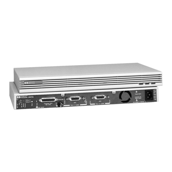
Page 13: Back Of The Bridge
(This LED is repeated on the front.) If this LED is ON and one of the Net Fail LEDs is also ON, the failure is associated with the network. If this LED is ON and a Net Fail LED is not ON, the bridge itself is at fault. Introducing the HP 10:10 LAN Bridge MB 1-5... -
Page 14: Port Status Leds
(if one has been configured). See “Clearing the Password” in chapter 4. When used simultaneously with the Reset button, it can erase all changes you have made to the bridge’s configuration. See “Resetting the Bridge” in chapter 4. 1-6 Introducing the HP 10:10 LAN Bridge MB... -
Page 15: Installation
Installation This chapter describes how to install and configure the HP 10:10 LAN Bridge MB, and verify that it is operating correctly. Installation Summary The steps to install the HP 10:10 LAN Bridge MB are: 1. Mount the bridge (in a rack, on a wall, or on a table). -
Page 16: Mount The Bridge
In the example below, the bridge is mounted in a rack with other HP EtherTwist family devices and a cable guide unit. Order the HP EtherTwist LAN Rack (HP 46298D) and the Cable Guide (HP 35199D). - Page 17 For Rack or Cabinet Mounting: 1. Using a Phillips or cross-head screwdriver, attach the mounting brackets to the bridge with 10-mm M4 screws (included in accessory kit). Note that the bridge’s case and the mounting brackets are designed to allow you to rack mount the bridge with either the back or the front facing out.
- Page 18 For Wall Mounting: Using a Phillips or cross-head screwdriver, attach the mounting brackets to the bridge with 10-mm M4 screws (included in the accessories kit). Then attach the ⁄ ⁄ bridge to a wood surface (minimum -in. plywood or equivalent) with -inch number 12 wood screws or equivalent (not included).
-
Page 19: Connect The Networks To The Bridge
Plug the power cord back in after the cables are reconnected. The HP 10:10 LAN Bridge MB connects to networks in these ways: To a thin coax, thick coax, fiber-optic, or twisted-pair cable network through transceivers attached to the bridge’s AUI connectors. -
Page 20: Using The Aui Connectors
Using the AUI Connectors 1. Slide the AUI retainer (included) onto the connector posts on a AUI port on AUI retainer bridge transceiver or an AUI cable. 2. Plug the transceiver or AUI cable into the AUI port on the bridge and secure it with the retainer’s screws. -
Page 21: Using The Thinlan Connector
Using the ThinLAN Connector 1. Attach a thin LAN cable section to one side of a BNC “T” connector. 2. Attach another thin LAN cable section or a 50-ohm terminator to the other side of the “T” connector. 3. Attach the “T” connector to the ThinLAN port. 50-ohm thin LAN thin LAN... -
Page 22: Plug In The Bridge And Verify
The HP 10:10 LAN Bridge MB has a power supply that automatically adjusts to any ac power source that provides between 90 and 240 volts. No voltage range setting is necessary. -
Page 23: Customize The Bridge's Configuration (If Needed)
No changes to the bridge’s default configuration are required for the bridge to operate correctly. The HP 10:10 LAN Bridge MB has a console interface for customizing the configuration, monitoring bridge activity, and running diagnostics. Proceed to chapter 3, “Configuration” for the procedures to connect a terminal to the bridge and customize the bridge’s configuration. -
Page 25: Configuration
Console Session” on the next page for the procedures to access and use the bride’s console interface. (The bridge can also be configured over the network from an HP network management station. See the network management product documentation for more information.) -
Page 26: Starting A Console Session
Starting a Console Session Connect a terminal to the bridge’s console port directly or through modems, as described below. Any terminal or terminal emulation program that can communicate using the ASCII TTY driver mode can be used. Connecting a Terminal Directly 1. -
Page 27: Connecting A Modem And Terminal
1. Use a full-duplex, asynchronous (character-mode) modem only. The following modems have been tested at their rated speeds: – HP 37212B Support Link – HP 35031A Support Link II – HP 50759A Support Link – Hayes 1200 Smartmodem – Racal Vadic Maxell 2400VP (Hayes 2400 compatible) –... -
Page 28: If You Have Trouble With A Terminal Or Modem Connection
1. Detach the console cable from the bridge. Attach the console port’s loopback connector to the bridge. (HP part no. 5062-3355––see appendix A, “Cables and Connectors”.) 2. Cycle power on the bridge by unplugging the power cord and plugging it in again. As part of its power-on self-test the bridge tests the console port. -
Page 29: Configuration Commands
IP (the Internet Protocol). If either of the following is true, you must set the IP configuration parameters on the bridge: The bridge will be managed remotely with a network management product, such as HP OpenView Interconnect Manager, over a TCP/IP network (a network operating system that uses IP communications). - Page 30 Note Novell NetWare uses the IPX protocol. If you are using the bridge on a Novell NetWare network, no configuration of the bridge is required for it to communicate with a network management station that is also using the IPX protocol.
- Page 31 IP Configuration Parameters: IP Address The IP address of the bridge, written in the format X.X.X.X. Each number between the decimal points is a decimal number between 0 and 255. Use from 1 to 254 in the fourth position. 0 and 255 are reserved values. Every IP address on a network must be unique.
-
Page 32: Operating State
OPerating State Enter OP at the Config prompt to display the current bridge operating state and to receive a prompt allowing you to specify a new operating state. The possible operating state values are Learning, Learning/STP, Secure, Secure/STP, and Bridge Off. Enter HE at the Operating State prompt to get help on completing this task. -
Page 33: Wildcard Filters
WIldcard Filters Enter WI at the Config prompt to display the current bridge wildcard filters and to receive a prompt allowing you to change (or create) or delete the wildcard filters. You can set a total of two wildcard filters. Enter HE at the Wildcard Filter prompt to get help on completing this task. - Page 34 Filtering on Vendor Code in the Destination Address: The first three bytes of the station address are consistent for a given vendor. For all Hewlett-Packard devices, for example, the first three bytes are 080009 (in hexadecimal). The destination address is the first field that is analyzed by the bridge in IEEE 802.3 and Ethernet packets, so the byte offset is 0.
-
Page 35: Operation
Operation The HP 10:10 LAN Bridge MB is designed to operate unattended. The console interface allows you to customize the bridge’s configuration, to monitor its status and activity, and to run diagnostics if the bridge or network encounters problems. Additionally, self-test routines can be run on the bridge to test its hardware and firmware and to remove some transient problem conditions. -
Page 36: Console Commands
Console Commands The procedures to connect a terminal to the bridge’s console port and to start a console session have already been covered in chapter 3, “Configuration” under “Starting a Console Session”. This section describes the rest of the console interface commands. The bridge’s console interface is command driven and has three menus of commands: Main Menu commands are used to set certain console session characteristics, to run diagnostics, and to access the other menus. -
Page 37: Main Menu Commands
Main Menu Commands Entering HE at the Main prompt lists the Main Menu commands. Figure 4-1. Main Menu Commands Displays a single screen listing all available console commands. HElp Lists and briefly explains the console commands that can be entered at the current prompt. (Figure 4-1 shows the help from the Main prompt). - Page 38 Once you set a password, you will be prompted for it each time you start a bridge console session and each time you use an HP network management product to change the bridge configuration. The same password is used for both applications.
- Page 39 PIng Runs a test of the path between the bridge and another device that responds to IP packets. The bridge sends Internet Control Message Protocol (ICMP) Echo Request packets to another node with the specified IP address and waits for Echo Response packets in return. When you run the Ping command, you will be prompted for: the IP address of the destination device (in the format X.X.X.X) the number of packets to send...
- Page 40 TEstlink Runs a test of the link between the bridge and another addressable device (a destination node) by sending IEEE 802.2 “test” packets to that node. You are prompted for: the destination node’s station address. the number of test packets to try. the timeout value (how many seconds the bridge will wait for a response from the destination node before reporting an error).
-
Page 41: Config Mode Commands
Config Mode Commands Entering HE at the Config prompt lists the Config Mode commands (see figure 4-2). Figure 4-2. Config Mode Commands Displays a single screen with all available console commands listed. HElp Lists and briefly explains the console commands that can be entered at the current prompt. (Figure 4-2 shows the help from the Config prompt.) The rest of the Config Mode commands are explained in detail in chapter 3, “Configuration”. -
Page 42: Status Mode Commands
Status Mode Commands Entering HE at the Status prompt lists the Status Mode commands (see figure 4-3). Figure 4-3. Status Mode Commands Displays a single screen with all available console commands listed. HElp Lists and briefly explains the console commands that can be entered at the current prompt. (Figure 4-3 shows the help from the Status prompt.) 4-8 Operation... - Page 43 Normal. If the value is WARNING! Bridge temperature over limit, the fan in the bridge power supply may have failed. In this case, you should unplug the bridge power cord and contact your HP authorized LAN dealer or local HP sales and support office. Operation 4-9...
- Page 44 COunters Displays data packet statistics and error indications for ports 1 and 2 individually. These statistics are provided: Bytes transmitted The number of bytes of data transmitted to destination nodes. Bytes received The number of bytes of data received from source nodes. Packets transmitted The number of 802.3 packets (MAC frames) or Ethernet packets transmitted to destination nodes.
-
Page 45: Resetting The Bridge
6, “How the Bridge Works”, and “Wildcard Filters” in chapter 3. “Configuration”. Resetting the Bridge Four methods for resetting the HP 10:10 LAN Bridge MB are available. They are designated as REset command, Reset button, cycle power, and Reset-Clear. Effects of the Reset Methods Each of these reset methods causes the bridge to execute self-test and re-initialize, but there are differences in the other effects of each reset. - Page 46 Table 4-1. Effects of Bridge Reset Methods Reset Mechanisms REset Reset Cycle Reset- Resulting Actions Command Button Power Clear Bridge executes an internal self-test, and an √ √ √ √ external loopback test on both network ports. √ Address table static entries are cleared. √...
-
Page 47: Executing The Reset Methods
Executing the Reset Methods To execute any of the reset methods, follow the appropriate procedure below. REset Command Enter RE from the Main prompt on the bridge console. Reset Button Press the button labeled Reset on the back on the bridge. The Pwr, Self-test, and Net Fail LEDs stay on while this button is pressed. -
Page 48: Clearing The Bridge Password
Password protection can be restored by using the Password command (PA) on the bridge console. See “PAssword” under “Main Menu Commands” in this chapter. The password can also be set or changed from an HP network management station. See your network management documentation for the procedures. 4-14 Operation... -
Page 49: Troubleshooting
Troubleshooting This chapter covers these topics: Basic troubleshooting tips Diagnosing with the LEDs Diagnostic tests – Testing the bridge only – Testing the bridge and LANs – Testing the links Basic Troubleshooting Tips Make sure the bridge is plugged in and that cable connections are secure. Note that during self-test and initialization, the bridge executes external loopback tests. -
Page 50: Diagnosing With The Leds
Check cables, connections, transceivers (if used), etc. For the bridge to pass self-test, a viable network or an HP loopback connector must be attached to one of the port 1 connectors and to the port 2 connector. - Page 51 Table 5-2. LED Patterns Showing Operational Failures LEDs Fault Suggested Actions Line On (front and Self-test Net Fail (on front) (on back) back) Fault detected during normal operation on the network attached to the indicated port. Check cables, connections, transceivers (if used), etc.
-
Page 52: Diagnostic Tests
Diagnostic Tests Testing the Bridge Only You can verify that the bridge is operational without having to attach it to the LANs by using loopback connectors on the network ports. See appendix A, “Cables and Connectors”, for information on the required connectors. To test the bridge by itself: 1. -
Page 53: Testing The Bridge And Lans
Testing the Bridge and LANs A bridge or LAN fault during normal operation will usually be indicated by the Fault and Net Fail LEDs (see table 5-2). To verify such an indication, or to investigate intermittent indications that your LANs do not appear to be communicating properly across the bridge, the fault can usually be isolated to either the bridge or the attached networks by executing a bridge reset. -
Page 54: Testing The Network Links
IP address. The destination node must be able to respond to the Echo Request packets for the test to work. Use HP network management software to test the link. For instructions, see the network management product’s documentation. If any errors are reported during these tests, there may be a fault on the LAN segment being tested, or on the destination node device. -
Page 55: How The Bridge Works
The Bridging Function When the HP 10:10 LAN Bridge MB receives a data packet on either of its two ports, it examines the packet to see if the node sending the packet (source node) is on the same LAN as the node for which the packet is intended (destination node). -
Page 56: Operating State
The bridge has five possible operating states: Learning, Learning/STP, Secure, Secure/STP, and Bridge Off. The default operating state is Learning. The current operating state can be changed through the bridge console interface, or from an HP network management station. Learning. The bridge automatically learns the addresses of the nodes communicating through the bridge and which side of the bridge each node is on. -
Page 57: Address Table
Address table changes can be made through the bridge console interface, or from an HP network management station. Dynamic Addresses. Dynamic addresses are the node addresses that the bridge learns after it is connected to the network. - Page 58 Static Addresses. Static addresses are entries that you manually add to the address table. These addresses remain in the address table until you intentionally delete them. The effect of these addresses varies depending on the operating state of the bridge: In learning mode (either Learning or Learning/STP operating states), you add static entries to the table to prevent communication to specific nodes.
-
Page 59: Wildcard Filters
Wildcard Filters The wildcard filter is a 32-bit binary pattern that can be applied to any 32-bit section at any location in received packets. The location is determined by specifying a byte offset (the distance in bytes from the beginning of the packet to the start of the section where the wildcard filter is to be applied). -
Page 60: Spanning Tree Support
Spanning Tree Support The HP 10:10 LAN Bridge MB uses the IEEE 802.1 Spanning Tree Protocol (STP). STP ensures that only one path at a time is active between any two nodes on the network. This allows you to have redundant bridges on the network as backup bridges. If an active bridge or path fails, STP automatically activates an available path through a backup bridge. - Page 61 The HP 10:10 LAN Bridge MB is pre-configured with the IEEE recommended values for the STP parameters. To extend your network beyond the seven-bridge limit without encountering errors due to excessive transmission times, you may need to modify the STP parameters.
-
Page 62: Automatic Network Verification
Bridge 1 or Bridge 2 fails, Bridge 3 will reconfigure to forward traffic between subnets B and C. If the HP 10:10 LAN Bridge MB is functioning as a root or forwarding bridge, it will discard or forward packets based on its operating state, address table entries, and wildcard filters. If the bridge is functioning as a backup bridge, all received packets (except those explicitly addressed to the bridge) are discarded. -
Page 63: Firmware Enhancements
Hewlett-Packard continually tests and improves its products. When firmware enhancements are made to the HP 10:10 LAN Bridge MB, you will be able to easily update it with the new code. The update can be made from a PC attached to the bridge’s console port (directly or through a modem), or the bridge’s new code can be downloaded over the network. - Page 64 When configured with an IP address, the bridge can also send and respond to network-layer test packets (ICMP Echo Request, or “Ping” packets). Using Non-HP Network Management. To manage the HP 10:10 LAN Bridge MB with a non-HP network management product, you must first obtain HP’s Network Management Information Base (MIB) extensions.
-
Page 65: Cables And Connectors
Cables and Connectors This appendix lists cables that have been tested and verified for use with the HP 10:10 LAN Bridge MB. The minimum pin-outs are shown, in case you wish to use an unlisted cable or manufacture your own. Note that each pin-out does not necessarily match the pin-out for the corresponding HP cable, but cables manufactured to follow the minimum pin-out will function correctly. -
Page 66: Hp Cables
25-pin male 31391A cable * An AUI cable is not necessary with some transceivers such as the HP 28685A or HP 28685B EtherTwist Transceivers, the HP 28641B ThinLAN Transceiver, and the HP 28683A Fiber-Optic Transceiver. These transceivers attach directly to the AUI port of a network device. -
Page 67: Other Standard Cables
Other Standard Cables Port Type on Standard Cable or Cable Function Terminal, PC, Cable Solution or Modem Connecting to the console port: Attach a null modem adapter † (Tandy Null Modem Adapter No. 26-1496 has been tested) to the console 25-pin female port. -
Page 68: Thin Lan Cable Requirements
Thin LAN Cable Requirements The thin coaxial cables used with the HP 10:10 LAN Bridge MB’s ThinLAN port must comply with the IEEE 802.3 Type 10Base2 requirements. Some RG-58 A/U or RG-58 C/U cable meet these requirements. The maximum length of a single thin coaxial cable segment is 185 meters. -
Page 69: Console Connector And Cable Pin-Outs
Console Connector and Cable Pin-Outs The HP 10:10 LAN Bridge MB has a console port that automatically detects whether a terminal or a modem is connected. No switch setting is required. Because of this function, a standard “straight-through” cable can not be used when connecting a terminal directly. -
Page 70: Rs-232-C "Crossover" Cable (For Terminal/Pc With 25-Pin Connector
RS-232-C “Crossover” Cable (for Terminal/PC with 25-Pin Connector) Minimum Pin-Out Terminal/PC end Bridge end 25-pin male 25-pin male RS-232-C “Crossover” Cable (for Terminal/PC with 9-Pin Connector) Minimum Pin-Out Terminal/PC end Bridge end 9-pin female 25-pin male A-6 Cables and Connectors... -
Page 71: Rs-232-C Cable For
RS-232-C Cable for HP 110 Minimum Pin-Out HP 110 end Bridge end 9-pin male 25-pin male Null-Modem Adapter (use with a modem cable when connecting a terminal) Minimum Pin-Out Modem cable end Bridge end 25-pin female 25-pin male DTR (pin 20) and RTS (pin 4) must be on, or high, on your terminal or in your terminal emulation program. -
Page 72: Rs-232-C Modem Cable
RS-232-C Modem Cable Minimum Pin-Out Modem end Bridge end 25-pin male 25-pin male Signal CD OR DCD DRS – typically on V.24 (European) modems A-8 Cables and Connectors... -
Page 73: Loopback Connectors
The three loopback connectors shown below are useful for troubleshooting your HP 10:10 LAN Bridge MB. These connectors are included in the HP Extended LAN Troubleshooting Kit, product number HP 28689B, or all three can be purchased separately. Contact your HP-authorized LAN dealer or your local HP sales office for assistance. -
Page 75: Product Specifications
(16.8 in by 9.3 in by 1.7 in) Weight: 2.7 kg (6.0 lb) Electrical (The HP 10:10 LAN Bridge MB automatically adjusts to any voltage between 90 and 240 volts and any frequency between 50 and 60 Hz.) ac voltage: 100–120 volts 200–240 volts... - Page 76 * These specifications are legal requirements in the indicated countries. Datacomm Declarations United Kingdom The HP 28673A is approved under Approval Number NS/G/1234/J/100003 for indirect connection to public telecommunications systems within the United Kingdom. Sweden Application and Declaration of Conformity to Swedish requirements has been filed.
-
Page 77: Modem Configuration
Modem Configuration HP 35031A Support Link II At the bridge Configure SOFT OPTION 6 to 1. end: Configure SOFT OPTION 15 to 2. Configure SOFT OPTION 16 to 2. Configure SOFT OPTION 20 to 2. Configure SOFT OPTION 21 to 2. -
Page 78: Black Box V.32 9600 Async
Black Box V.32 9600 Async. At the bridge Load the factory option set #1. Then make these changes: end: Data Rate Menu: change to 9600 uncoded – – Modem Parameters Menu: change to Forced Answer – DTE Parameters Menu: – set DTR State to Responds to DTR Change –... -
Page 79: D Network Addressing
Network Addressing The HP 10:10 LAN Bridge MB can be managed over the network by HP network management products, and any other network management products that use the Simple Network Management Protocol (SNMP). The communication between the SNMP network management station and the bridge takes place using the network layer protocols, IPX for Novell networks, or IP for TCP/IP networks. -
Page 80: Ip Addresses For Tcp/Ip Networks
IPX Addressing Notes: Because the IPX address is assigned automatically, no IPX configuration is necessary; no IPX configuration is provided on the bridge console interface. By default, the bridge is ready to be managed by an SNMP network management station that is configured for IPX communications. -
Page 81: Building Your Own Ip Addressing Scheme
The following documents have detailed descriptions on how to build your own IP addressing scheme: HP OpenView EtherTwist Network Management DOS Reference Guide HP part number 5091-3635E Internetworking With TCP/IP: Principles, Protocols, and Architecture Author: Douglas E. Comer Publisher: Prentice-Hall, Inc. - Page 82 The fourth integer must be unique for each addressed device. (Do not use 0 or 255 in the fourth position. They are reserved integers.) For three bridges and an HP network management station on the network, the class C addresses might be: management station 192.1.1.1...
-
Page 83: Ethernet Packet Types And Vendor Codes
Ethernet Packet Types and Vendor Codes Table E-1 is a list of Ethernet packet types (found in the 13th and 14th octets of an Ethernet packet). Table E-2 is a list of vendor codes (the first three bytes of the station address). These lists are subject to change. - Page 84 Table E-1. Ethernet Packet Types (continued) Packet Type Company 0A00 Xerox IEEE 802.3 PUP 0A01 Xerox IEEE 802.3 PUP Address Translation 0BAD Banyan Systems not listed 1000 Berkeley Trailer negotiation 1001-100F Berkeley Trailer encapsulation for IP 1600 SIMnet (BBN) private protocol 5208 SIMnet (BBN) private protocol...
- Page 85 Table E-1. Ethernet Packet Types (continued) Packet Type Company 8005 Hewlett-Packard HP Probe protocol 8006 Nestar not listed 8008 AT&T not listed 8010 Excelan not listed 8013 Silicon Graphics not listed 8014 Silicon Graphics Diagnostics 8015 Silicon Graphics Network games...
- Page 86 Table E-1. Ethernet Packet Types (continued) Packet Type Company 8044 Planning Research Co. not listed 8046-8047 AT&T not listed 8049 ExperData not listed 805B-805C Stanford University V kernel, experimental 805D Evans & Sutherland not listed 8060 Little Machines not listed 8062 Counterpoint Computers not listed...
- Page 87 Table E-1. Ethernet Packet Types (continued) Packet Type Company 80A4-80B3 Seimens Gammasonics not listed 80C0-80C3 Digital Comm. Assoc. (DCA) Data Exchange Cluster 80C6 Pacer Software not listed 80C7 Applitek Corp. not listed 80C8-80CC Integraph Corp. not listed 80CD-80CE Harris Corp. not listed 80CF-80D3 Taylor Instrument...
- Page 88 Packet Type Company 9000 MOP LAN Loopback 9001 Bridge Communications XNS Systems Management 9002 Bridge Communications TCP/IP Systems Management 9003 Bridge Communications not listed FF00 private protocol Table E-2. Station Address Vendor Codes Code Vendor 00000C Cisco 000020 DIAB 000022 Visual Technology 00002A 00003D...
- Page 89 Table E-2. Station Address Vendor Codes (continued) Code Vendor 0000C0 Western Digital 0000D0 Gould 0000E2 Acer Counterpoint 000102 BBN - BBN internal usage (not registered) 001700 Kabel 00AA00 Intel 00DD00 Ungermann-Bass 00DD01 Ungermann-Bass MICOM/Interlan - UNIBUS or QBUS machines, 020701 Apollo (Hewlett-Packard) 020406 BBN - BBN internal usage (not registered)
- Page 90 Table E-2. Station Address Vendor Codes (continued) Code Vendor 08001B Data General 08001E Apollo (Hewlett-Packard) 080020 Sun - Sun machines 080022 080025 080028 TI - Explorer 08002B 080036 Integraph - CAE stations 080039 Spider Systems 080047 Sequent 080049 Univation 08004C Encore 08004E BICC...
- Page 91 Table E-2. Station Address Vendor Codes (continued) Code Vendor 08008D XyVision - XyVision machines DEC - global physical address for some older DEC AA0003 interfaces AA0004 DEC - local logical address for systems running DECNET Ethernet Packet Types and Vendor Codes E-9...
-
Page 93: Safety Information
Safety Information Safety Symbols Documentation reference symbol. If the product is marked with this symbol, refer to the product documentation to get more information about the product. WARNING A WARNING in the manual denotes a hazard that can cause injury or death. CAUTION A CAUTION in the manual denotes a hazard that can damage equipment. - Page 94 Informations concernant la sécurité Symboles de sécurité Symbole de référence à la documentation. Si le produit est marqué de ce symbole, reportez-vous à la documentation du produit afin d’obtenir des informations plus détaillées. AVERTISSEMENT Dans la documentation, un AVERTISSEMENT indique un danger susceptible d’entraîner des dommages corporels ou la mort.
- Page 95 Hinweise zur Sicherheit Sicherheitssymbole Symbol für Dokumentationsverweis. Wenn das Produkt mit diesem Symbol markiert ist, schlagen Sie bitte in der Produktdokumentation nach, um mehr Informationen über das Produkt zu erhalten. VORSICHT Eine VORSICHT in der Dokumentation symbolisiert eine Gefahr, die Verletzungen oder sogar Todesfälle verursachen kann.
- Page 96 Considerazioni sulla sicurezza Simboli di sicurezza Simbolo di riferimento alla documentazione. Se il prodotto è contrassegnato da questo simbolo, fare riferimento alla documentazione sul prodotto per ulteriori informazioni su di esso. PERICOLO La dicitura PERICOLO denota un pericolo che può causare lesioni o morte. ATTENZIONE La dicitura ATTENZIONE denota un pericolo che può...
- Page 97 Consideraciones sobre seguridad Símbolos de seguridad Símbolo de referencia a la documentación. Si el producto va marcado con este símbolo, consultar la documentación del producto a fin de obtener mayor información sobre el producto. ADVERTENCIA Una ADVERTENCIA en la documentación señala un riesgo que podría resultar en lesiones o la muerte.
- Page 98 Safety Information 6 Safety Information...
-
Page 99: Regulatory Statements
Regulatory Statements FCC Statement (For U.S.A. Only) Federal Communications Commission Radio Frequency Interference Statement Warning: This equipment generates, uses, and can radiate radio frequency energy. If it is not installed and used in accordance with the instruction manual, it may cause interference to radio communications. It has been tested and found to comply with the limits for a Class A computing device pursuant to Part 15 of FCC Rules, which are designed to provide reasonable protection against such interference when operated in a commercial environment. - Page 100 Declaration of The following Declaration of Conformity complies with ISO/IEC Guide 22 and EN 45014. It identifies the product, Conformity the manufacturer’s name and address, and the applicable specifications that are recognized in the European community. 2 Safety Information...
-
Page 101: One-Year Limited Hardware Warranty
Hewlett-Packard warrants this computer hardware product against defects in materials and workmanship for a period of one year from receipt by the end user. If HP receives notice of such defects during the warranty period, HP will, at its option, either repair or replace products that prove to be defective. - Page 102 HP has conducted limited testing with certain non-HP products to determine compatibility with the HP 28673A 10:10 LAN Bridge MB. Please contact your HP authorized LAN dealer or HP representative for the current list of tested products. HP relies in part upon information from the suppliers of non-HP products and makes no warranty, expressed or implied, with respect to the operation of these products or their compliance with worldwide regulatory requirements.
-
Page 103: Glossary
An attachment unit interface (AUI) cable. This cable connects the AUI port of a bridge to a transceiver. Some transceivers have a cable permanently attached, others require a separate cable. HP offers a set of compaact transceivers that attach directly to the bridge’s AUI ports. - Page 104 BNC connector Any of several connectors used for thin coaxial cable. There are male and female connectors used to connect sections of a LAN and the “T” connector used for attaching devices to the cable. bridge A device providing an intelligent connection between two otherwise independent LANs. Bridges operate at layer 2 of the ISO OSI reference model.
- Page 105 data packet See packet. Ethernet A LAN developed by Xerox Corp., Digital Equipment Corp., and Intel Corp. It uses the CSMA/CD method of access and transmits at 10 Mbit/s on a bus topology. The IEEE 802.3 standard evolved from Ethernet, but they are not exactly the same. Network devices based on both standards can co-exist on the same medium, but they cannot exchange data directly without special, “bi-lingual”, software that can decode packets of both types.
- Page 106 forwarding The process by which the bridge transfers a packet received from one LAN to the port for transmission onto the other LAN. IEEE 802.3 standard Part of the Institute of Electrical and Electronics Engineers 802 family of LAN standards. The 802.3 standard defines the physical layer (layer 1) and part of the data link layer (layer 2) of the ISO OSI reference model for a CSMA/CD LAN.
- Page 107 MAC address See station address. MAC frame See packet. medium attachment unit See transceiver. Mbit/s Megabits per second (1,000,000 bits per second). medium, media The transmission connection between nodes. Most current LANs use cables (fiber-optic or copper), although radio and other broadcast media are possible. node A computer or other addressable device on a network, including PCs, terminals, bridges, routers, and mainframes.
- Page 108 An input/output device that permits interaction with a bridge or computer. The device can be a display and keyboard, or a personal computer. See also console. ThickLAN A local area network (LAN) operating over 10-mm diameter coaxial LAN cable. HP ThickLAN networks are compatible with the IEEE 802.3 Type 10Base5 standard. 6-Glossary...
- Page 109 ThinLAN A LAN operating over 5-mm diameter coaxial LAN cable. HP ThinLAN networks are compatible with the Type 10Base2 standard. transceiver The assembly used to provide the physical connection and access to a LAN. It is the device on the LAN that detects collisions. (A transceiver is also called a medium attachment unit or MAU in the IEEE 802.3 standard.)
-
Page 111: Index
Index address table configuration process ..... 3-5 description ......6-3 effect of changing operating state on . - Page 112 AUI cable description ..... A-4 available from HP ..... . . A-2 console connection .
- Page 113 console access password ......4-4 cables for connecting ..... . A-5 command menus .
- Page 114 electromagnetic specifications ....B-2 EPROM code version ..... . . 4-9 Ethernet packet type list of known values .
- Page 115 using the AUI connector ....2-6 using the ThinLAN connector ....2-7 verifying bridge operation .
- Page 116 main menu commands ..... . 4-3 media speed performance ..... 1-2 modem for console connection .
- Page 117 operating state configuration process ..... 3-8 descriptions ......6-2 determining the bridge’s current state .
- Page 118 RAM code version ......4-9 Receive LED ......1-6 reset button description .
- Page 119 starting a console session ..... 3-2 static address adding to the address table ....3-5 definition .
- Page 120 ThinLAN Enabled LED ..... . 1-6 ThinLAN loopback connector ....A-9 TIme command .
-
Page 121: Regulatory Information
Regulatory Information The product described in this document complies with specific international regulations. See the document section entitled “Regulatory Statements” for the applicable regulatory information. Informations concernant la réglementation Le produit décrit dans le présent document satisfait à des normes internationales spécifiques. Pour plus de détails sur les réglementations applicables, reportez-vous à... - Page 122 © Copyright 1992 Hewlett-Packard Company Printed in U.S.A. 03/92 Manual Part Number 28673-90001...
Need help?
Do you have a question about the 10:10 LAN Bridge MB and is the answer not in the manual?
Questions and answers