
Related Manuals for HP HPE Edgeline EL1000


Summary of Contents for HP HPE Edgeline EL1000
- Page 1 HPE Edgeline EL1000 System User Guide HPE Edgeline EL1000 System User Guide Part Number: 10-191019-Q321 Published: May 2021 Edition: 1...
- Page 2 HPE Edgeline EL1000 System User Guide HPE Edgeline EL1000 System User Guide Abstract Abstract This document is for the person who installs, administers, and troubleshoots servers and storage systems. Hewlett Packard Enterprise assumes you are qualified in the servicing of computer equipment and trained in recognizing hazards in products with hazardous energy levels.
-
Page 3: Table Of Contents
Table of contents Table of contents 1 Component identification 1.1 PCIe configuration 1.1.1 Front panel components 1.1.2 Front panel LEDs and buttons 1.1.3 Right side components 1.1.4 System board components 1.2 PXI/PXIe configuration 1.2.1 Front panel components 1.2.2 Front panel LEDs and buttons 1.2.3 Right side components 1.2.3.1 Mini-PCIe module port-cable mapping 1.2.4 System board components... - Page 4 4.1 Installing the wall mounting option kit 4.2 Installing the rack mounting option kit 4.3 Installing the ETSI rack mounting option kit 4.4 Installing the Enterprise rack mounting option kit 4.5 Installing the drive 4.6 Installing the card options 4.6.1 Install the PCIe card 4.6.2 Install the PXI/PXIe card 4.7 Installing the mini-PCIe module options 4.7.1 Install a half-length mini-PCIe WiFi module option...
- Page 5 6.6 HPE Edgeline Infrastructure Manager 6.7 UEFI System Utilities 6.7.1 Using UEFI System Utilities 6.7.2 Flexible boot control 6.7.3 Restoring and customizing configuration settings 6.7.4 Secure Boot configuration 6.7.5 Embedded UEFI shell 6.7.6 Embedded Diagnostics option 6.7.7 iLO RESTful API support for UEFI 6.7.8 Re-entering the server serial number and product ID 7 Troubleshooting 7.1 HPE Edgeline Troubleshooting Guide...
- Page 6 12.1 Websites 12.2 Accessing Hewlett Packard Enterprise Support 12.3 Accessing updates 12.4 Customer self repair 12.5 Remote support 13 Acronyms and abbreviations 14 Documentation feedback...
-
Page 7: Component Identification
Component identification Component identification This chapter describes the external and internal server features and components. Component identification... -
Page 8: Pcie Configuration
PCIe configuration PCIe configuration PCIe configuration... -
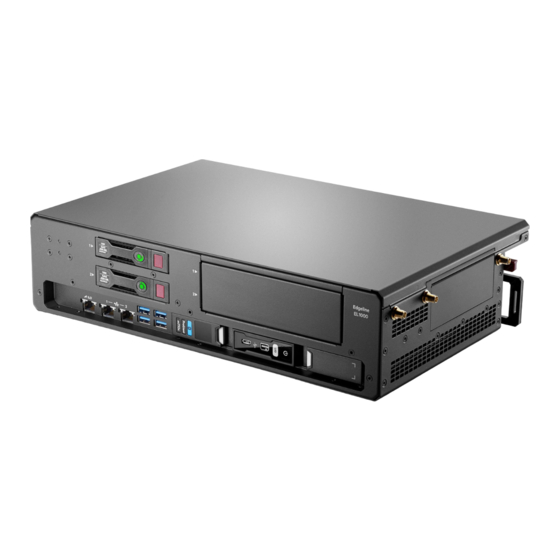
Page 9: Front Panel Components
Front panel components Front panel components Item Item Description Description iLO port Network port 1 Network port 2 USB 3.0 ports Drives Blade Network connections are available in 1G and 10G. The 1G is shown. Front panel components... -
Page 10: Front Panel Leds And Buttons
Front panel LEDs and buttons Front panel LEDs and buttons Item Item Description Description Status Status iLO and network port link LED Green = Linked to network Off = No network connection iLO and network port activity Flashing green = Network activity Off = No network activity Blade UID LED/button Blue = Blade ID is selected... -
Page 11: Right Side Components
Right side components Right side components Item Item Description Description Antenna connectors (LTE/3G/4G) Antenna connectors (WiFi) Power supply PCIe slot 2 PCIe slot 1 Right side components... -
Page 12: System Board Components
System board components System board components Item Item Description Description Fan 1 Fan 2 Fan 3 Power distribution board System battery System board components... -
Page 13: Pxi/Pxie Configuration
PXI/PXIe configuration PXI/PXIe configuration PXI/PXIe configuration... -
Page 14: Front Panel Components
Front panel components Front panel components Item Item Description Description iLO port Network port 1 Network port 2 USB 3.0 ports (4) Drives (2) Blade PXI/PXIe slot 3 PXI/PXIe slot 2 1G network connection Front panel components... -
Page 15: Front Panel Leds And Buttons
Front panel LEDs and buttons Front panel LEDs and buttons Item Item Description Description Status Status iLO and network port link LED Green = Linked to network Off = No network connection iLO and network port activity Flashing green = Network activity Off = No network activity Blade UID LED/button Blue = Blade ID is selected... -
Page 16: Right Side Components
Right side components Right side components Item Item Description Description Antenna connector 1 (LTE/3G/4G) Antenna connector 4 (WiFi) Reserved Antenna connector 5 (WiFi) REF in connector REF out connector Antenna connector 3 (LTE/3G/4G) Power supply Right side components... -
Page 17: Mini-Pcie Module Port-Cable Mapping
Mini-PCIe module port-cable mapping Mini-PCIe module port-cable mapping Table 1: LTE module port-cable mapping Table 1: LTE module port-cable mapping LTE module cable port Cable color LTE module cable port Cable color Antenna connector Antenna connector Port 1 Black Antenna connector 1 Port 2 White (not used) Reserved... -
Page 18: System Board Components
System board components System board components Item Item Description Description Fan 1 Fan 2 Fan 3 DIP Switch Power distribution board System battery The fan cage might have to be removed to access the switch System board components... -
Page 19: Dip Switch
DIP switch DIP switch Position Position Default Default Function Function Off = Fan normal mode On = Fan high mode DIP switch... -
Page 20: Hot-Plug Drive Led Definitions
Hot-plug drive LED definitions Hot-plug drive LED definitions When a drive is configured as part of a Smart Array and connected to a powered-up controller, the drive LEDs indicate the condition of the drive. If no Smart Array adapter is present, then these drives will not be hot pluggable, but will still show the activity LEDs. Item LED Item Status... -
Page 21: Hpe H240 Smart Host Bus Adapter Port Identification
HPE H240 Smart Host Bus Adapter port identification HPE H240 Smart Host Bus Adapter port identification Item Item Description Description Port 1 Port 2 Box 1 is drive 1 and box 2 is drive 2 for both ports. HPE H240 Smart Host Bus Adapter port identification... -
Page 22: Operations
Operations Operations This chapter describes the hardware operations carried out prior to and after installing or removing a hardware option, or performing a server maintenance or troubleshooting procedure. Before performing these hardware operations, review and observe the server warnings and cautions. Operations... -
Page 23: Install An Ac Power Supply
Install an AC power supply Install an AC power supply Procedure Procedure 1. Align the power supply to the system. 2. Insert the power supply until it locks in place. 3. Connect the power cord and tie wrap the cable. Install an AC power supply... -
Page 24: Install The Dc Power Supply
Install the DC power supply Install the DC power supply Procedure Procedure 1. Remove the ring tongue from the top of the power supply. 2. Crimp the ring tongue to the ground cable from the -48V power source. 3. Remove the black connector from the rear of the power supply. Install the DC power supply... - Page 25 4. Loosen the screws on the connector. 5. Attach the (earthed) cable to the ground screw and washer and tighten to 13 lb-in of torque. The ground cable must be connected before connecting the -48V wire and return wire. Install the DC power supply...
- Page 26 6. Insert the -48V wire into the left side of the connector and tighten the screw to 10 lb-in of torque. 7. Insert the return wire into the right side of the connector and tighten the screw to 10 lb-in of torque. Install the DC power supply...
- Page 27 8. Insert the power supply into the power supply bay until it clicks into place. 9. Insert the connector into the power supply. Install the DC power supply...
- Page 28 10. Attach the cables to the power supply handle with the hook-and-loop strap. 11. Route the power cord. Use best practices when routing power cords and other cables. A cable management arm is available to help with routing. To obtain a cable management arm, contact a Hewlett Packard Enterprise authorized reseller. 12.
-
Page 29: Power Down The System
Power down the system Power down the system Before powering down the system for any upgrade or maintenance procedures, back up critical system data and programs. Before performing chassis maintenance, shut down all blades installed in the system. Procedure Procedure Use one of the following methods to power down the system: Press and release the Power On/Standby button of the blades installed in the system. -
Page 30: Power Up The System
Power up the system Power up the system If the system is connected to a power source, it powers up automatically by default. Generally, it has to be powered up only after a manual shutdown. However, using iLO, blades can be individually configured to not power up automatically. Procedure Procedure Use one of the following methods to power up the system:... -
Page 31: Mount The System
Mount the system Mount the system The following kits are available to mount your system: Wall mounting kit Rack mounting kit ETSI rack mounting kit Enterprise rack mounting kit Mount the system... -
Page 32: Dismount The System
Dismount the system Dismount the system Dismount the system, based on the mount installed: Dismounting the system from a wall mount Dismounting the system from a rack mount Dismounting the system from an ETSI rack mount Dismounting the system from an Enterprise rack mount Dismount the system... -
Page 33: Dismounting The System From A Wall Mount
Dismounting the system from a wall mount Dismounting the system from a wall mount To dismount the system from a wall mount, slide the EL1000 system off the wall-mounting screws. It is not necessary to remove the wall mounting plate from the EL1000 system. Hewlett Packard Enterprise recommends having a cart to place the system upon, which allows you to service the system without removing the wall mounting plate or cables. -
Page 34: Dismounting The System From A Rack Mount
Dismounting the system from a rack mount Dismounting the system from a rack mount Procedure Procedure 1. Loosen the 2 captive screws on the front of rack mount shelf. 2. Slide the EL1000 system and shelf out from the rack mounts to the front. 3. -
Page 35: Dismounting The System From An Etsi Rack Mount
Dismounting the system from an ETSI rack mount Dismounting the system from an ETSI rack mount Procedure Procedure 1. Loosen the 2 captive screws on the front of rack mount shelf. 2. Slide the EL1000 system and shelf out from the rack mounts to the front. 3. -
Page 36: Dismounting The System From An Enterprise Rack Mount
Dismounting the system from an Enterprise rack mount Dismounting the system from an Enterprise rack mount Procedure Procedure 1. Slide the system out of the rack. 2. Unplug the power cable and disconnect all cables from the system. 3. Remove the retention bracket from the Enterprise rack mount. 4. -
Page 37: Remove The Access Panel
Remove the access panel Remove the access panel Procedure Procedure Using a Torx driver, remove the two T10 Torx screws securing the access panel to the system. Remove the access panel... -
Page 38: Install The Fans
Install the fans Install the fans Procedure Procedure 1. Align the fan with the fan slots of the system. 2. Squeeze the tabs on either side of the fan, and then slide it into the bay until it clicks in place. Install the fans... -
Page 39: Install The Blade
Install the blade Install the blade No blade supported on the system support Legacy BIOS Boot mode. For more information, see the user and maintenance guide for your blade. Procedure Procedure Align and install the blade into the system. Install the blade... -
Page 40: Remove The Blade
Remove the blade Remove the blade Procedure Procedure 1. Power down the system . 2. Dismount the system. 3. Press the blade latch buttons and open the latches. 4. Remove the blade. Remove the blade... -
Page 41: Install The Mini-Pcie Adapter Board
Install the mini-PCIe adapter board Install the mini-PCIe adapter board Procedure Procedure 1. Align the mini-PCIe adapter board to the system board. 2. Using a Torx driver, insert and tighten the three T-15 Torx screws to secure the adapter board to the system board. 3. -
Page 42: Install The Antenna
Install the antenna Install the antenna Perform one of the following procedures depending on the type of antenna installed: Installing the WiFi or LTE antennas . Installing the WiFi and LTE combo antennas . Install the antenna... -
Page 43: Installing The Wifi Or Lte Antennas
Installing the WiFi or LTE antennas Installing the WiFi or LTE antennas Procedure Procedure 1. Power down the system . 2. Dismount the system. 3. Locate the correct antenna. For antenna connector locations, see PCI right side components or PXI right side components . 4. -
Page 44: Installing The Wifi And Lte Combo Antennas
Installing the WiFi and LTE combo antennas Installing the WiFi and LTE combo antennas You can connect WiFi antenna cables only, LTE antenna cables only, or the WiFi and LTE antenna cables together. Procedure Procedure 1. Power down the system . 2. -
Page 45: Setup
Setup Setup Setup... -
Page 46: Optional Services
Optional services Optional services For information on the optional services offered, see the product QuickSpecs on the Hewlett Packard Enterprisewebsite ( http://www.hpe.com/info/qs). http://www.hpe.com/info/qs Optional services... -
Page 47: Optimum Environment
Optimum environment Optimum environment When installing the system, select a location that meets the environmental standards. Temperature requirements Power requirements Optimum environment... -
Page 48: Temperature Requirements
Temperature requirements Temperature requirements To ensure continued safe and reliable equipment operation, install or position the system in a well-ventilated, climate-controlled environment. Configuration Configuration Temperature Temperature Chassis with blades installed, but no PCIe cards/PXIe modules installed Operating temperature of up to 55°C (131°F) Temperature requirements... -
Page 49: Power Requirements
Power requirements Power requirements Installation of this equipment must comply with local and regional electrical regulations governing the installation of information technology equipment by licensed electricians. This equipment is designed to operate in installations covered by NFPA 70, 1999 Edition (National Electric Code) and NFPA-75, 1992 (code for Protection of Electronic Computer/Data Processing Equipment). -
Page 50: Installing Hardware Options
Installing hardware options Installing hardware options Install any hardware options before initializing the system. For options installation information, see the option documentation. For system-specific information, see Hardware options installation. Installing hardware options... -
Page 51: Registering The Product
Registering the product Registering the product To experience quicker service and more efficient support, register the product at the Hewlett Packard Enterprise Product Registration Hewlett Packard Enterprise Product Registration website. website Registering the product... -
Page 52: Hardware Options Installation
Hardware options installation Hardware options installation Hardware options installation... -
Page 53: Installing The Wall Mounting Option Kit
Installing the wall mounting option kit Installing the wall mounting option kit Procedure Procedure 1. Using the wall mount bracket, mark the locations for the wall mount screws. 2. Install the wall mount anchors and screws in the marked locations. 3. -
Page 54: Installing The Rack Mounting Option Kit
Installing the rack mounting option kit Installing the rack mounting option kit The following rack kits are available: A 19 inch rack kit A 23 inch rack kit Procedure Procedure 1. Align the rack mount bracket to the system. 2. Using a Torx driver, insert and tighten the four T-10 Torx screws to secure the bracket to the system: 19 inch rack kit 23 inch rack kit Installing the rack mounting option kit... - Page 55 3. Install the system in the rack mount. Installing the rack mounting option kit...
-
Page 56: Installing The Etsi Rack Mounting Option Kit
Installing the ETSI rack mounting option kit Installing the ETSI rack mounting option kit Procedure Procedure 1. Align the rack mount bracket to the system. 2. Using a Torx screwdriver, insert and tighten four T-10 Torx screws to secure the bracket to the system. 3. -
Page 57: Installing The Enterprise Rack Mounting Option Kit
2. Install the cable management arm. For more information on installing the cable management arm, see the HP 1U Cable Management Arm Option Installation Instructions that ships with the cable management arm kit. 3. Install the Enterprise rack mount onto the rails. - Page 58 5. Align and install the system. 6. Install the retention bracket. Installing the Enterprise rack mounting option kit...
-
Page 59: Installing The Drive
Installing the drive Installing the drive Procedure Procedure 1. Align the drive to the drive bay, and slide it into the bay until it clicks in place. 2. Close the locking latch to secure the drive. Installing the drive... -
Page 60: Installing The Card Options
Installing the card options Installing the card options Depending on the configuration of your system, perform one of the following procedures: Install the PCIe card Install the PXI/PXIe card Installing the card options... -
Page 61: Install The Pcie Card
Install the PCIe card Install the PCIe card The system supports optional PCIe cards. IMPORTANT: The PCIe card is not hot-pluggable. The system must be powered down to install this card. IMPORTANT: Procedure Procedure 1. Power down the system . 2. - Page 62 7. Disconnect the hard drive backplane cable and any other cables that connect to the PCIe cards. 8. Align the PCIe card to the PCIe slot on the side of the system, and then slide it in until it clicks in place. Install the PCIe card...
-
Page 63: Install The Pxi/Pxie Card
Install the PXI/PXIe card Install the PXI/PXIe card The system supports optional PXI cards. NOTE: NOTE: The PXI/PXIe card is not hot-pluggable. The system must be powered down to install this card. Procedure Procedure 1. Power down the system . 2. - Page 64 Install the PXI/PXIe card...
-
Page 65: Installing The Mini-Pcie Module Options
Installing the mini-PCIe module options Installing the mini-PCIe module options You can install the following mini-PCIe modules on the mini-PCIe adapter board: Up to two half-length mini-PCIe WiFi modules Up to two full-length mini-PCIe LTE modules Wireless certification qualifies LTE option in mini-PCIe module slot 1 and WiFi option in mini-PCIe module slot 2. Installing the mini-PCIe module options... -
Page 66: Install A Half-Length Mini-Pcie Wifi Module Option
Install a half-length mini-PCIe WiFi module option Install a half-length mini-PCIe WiFi module option You will need a half-length mini-PCIe module adapter provided with the WiFi option kit to install this option. Procedure Procedure 1. Power down the system . 2. - Page 67 7. Install the two internal antenna cables on the antenna connectors on the module. 8. Install the two internal antenna cables to the antenna connector ports. For antenna connector locations, see PCI right side components or PXI right side components . 9.
-
Page 68: Installing A Full-Length Mini-Pcie Lte Module
Installing a full-length mini-PCIe LTE module Installing a full-length mini-PCIe LTE module Procedure Procedure 1. Power down the system . 2. Remove the blade, if installed. 3. Remove the access panel . 4. Align the full-length mini-PCIe module with the full-length slot on the mini-PCIe adapter board. 5. - Page 69 9. Install the antenna. Installing a full-length mini-PCIe LTE module...
-
Page 70: Installing The Nvme M.2 Ssd Option
Installing the NVMe M.2 SSD option Installing the NVMe M.2 SSD option IMPORTANT: When installing the M.2 SSD adapter card, the top slot of the PCI cage is preferred as slot 1. IMPORTANT: Prerequisites Prerequisites Before you perform this procedure, make sure that you have the following items available: T-15 screwdriver Philips screwdriver NVMe SSD module... - Page 71 7. Install the NVMe M.2 SSD on Bay 1 of the adapter card: a. Insert the SSD into the SSD slot at a 45 degree angle. b. Carefully press the SSD down to the horizontal position. c. Install the SSD mounting screw. d.
- Page 72 M.2 adapter installed in slot 1 and 2 9. Install the PCI cage in the server, and secure it with three T-15 screws. 10. Connect all the necessary cables. Installing the NVMe M.2 SSD option...
- Page 73 11. Install the blade . 12. Install the access panel and secure it with two T-10 screws. 13. Connect power cord to the system. 14. Connect power cord to the power source. 15. Power up the system. Installing the NVMe M.2 SSD option...
-
Page 74: Configuration
Configuration Configuration Configuration... -
Page 75: Accessing The System Utilities Menu
Accessing the System Utilities menu Accessing the System Utilities menu To complete these steps, you need the HPE USB-to-serial cable (HPE part number 871947-B21). Table 3: Settings for connecting USB cable to serial port Table 3: Settings for connecting USB cable to serial port Specifications Specifications Value... - Page 76 Accessing the System Utilities menu...
-
Page 77: Finding The Ip Address For An Ilo On System Blades
Finding the IP address for an iLO on system blades Finding the IP address for an iLO on system blades System blades contain an iLO processor. However, not all system blades have a local keyboard, video, and mouse solution to help identify the IP address assigned to the iLO. -
Page 78: Using Dynamic Dns To Access The Ilo
Using dynamic DNS to access the iLO Using dynamic DNS to access the iLO Prerequisites Prerequisites Your network supports Dynamic DNS. Procedure Procedure 1. Launch a browser. 2. To attempt to access the management interface, enter the DNS name on your tag into the browser. For example, if the name on your tag is 'ilo12345', enter one of the following in the browser: http://ilo12345 http://ilo12345.your.domain.name... -
Page 79: Using The Mac Address To Identify The Ip Address Of The Ilo
Using the MAC address to identify the IP address of the iLO Using the MAC address to identify the IP address of the iLO If your network does not support Dynamic DNS, you can identify the IP address by looking for the MAC address of your iLO in your DHCP server lease records, or log files. -
Page 80: Using Nmap To Identify The Ip Address Of The Ilo
Using NMAP to identify the IP address of the iLO Using NMAP to identify the IP address of the iLO Prerequisites Prerequisites You are permitted to scan your network You know the MAC address of your network (as mentioned in the identification tag of the blade) Procedure Procedure 1. -
Page 81: Configuring The Dhcp Server For Windows On Your Laptop
Configuring the DHCP server for Windows on your laptop Configuring the DHCP server for Windows on your laptop The DHCP Server for Windows application does not have to be installed in the system. It can be downloaded and run. Prerequisites Prerequisites Your laptop must be directly connected to the management port of the chassis. - Page 82 The Supported Protocols window appears. 10. Select the HTTP HTTP box, and optionally, the DNS DNS box, and then click the Next Next button. The Configuring DHCP for Interface window appears. 11. Enter the range of IP addresses that your DHCP server can use to assign to DHCP clients, and then click the Next Next button.
- Page 83 The Writing the INI file window appears. 12. Click the Write INI file Write INI file button, and then click the Next Next button. Clicking the Write INI file button saves the configuration file, and enables you to start the service. The DHCP server window appears.
- Page 84 14. Click Yes Yes at the conformation window. 15. Click the Continue as tray app Continue as tray app button in the same window. The DHCP server icon appears on the system tray. 16. Right-click the DHCP server icon on the system tray. 17.
-
Page 85: Setting The Static Ip Address Using The Serial Console Cable
Setting the static IP address using the serial console cable Setting the static IP address using the serial console cable Procedure Procedure 1. Using iLO 4 configuration utility 2. Using iLO 5 configuration utility Setting the static IP address using the serial console cable... -
Page 86: Using Ilo 4 Configuration Utility
Using iLO 4 configuration utility Using iLO 4 configuration utility Procedure Procedure 1. Access the System Utilities menu . 2. Navigate through the menu options System Configuration System Configuration > iLO 4 Configuration Utility iLO 4 Configuration Utility > Network Options Network Options. -
Page 87: Using Ilo 5 Configuration Utility
Using iLO 5 configuration utility Using iLO 5 configuration utility This step is required only if you want to use a static IP address. When you use dynamic IP addressing, the DHCP serverautomatically assigns an IP address for iLO. To simplify installation, Hewlett Packard Enterprise recommends using DNS or DHCP with iLO. Procedure Procedure 1. -
Page 88: Viewing Or Updating The Dhcp Address Using The Serial Console Cable
Viewing or updating the DHCP address using the serial console cable Viewing or updating the DHCP address using the serial console cable Procedure Procedure 1. Access the System Utilities menu . 2. For iLO 4, navigate through the menu options System Configuration System Configuration >... -
Page 89: Finding The Ip Address Through Dhcp
Finding the IP address through DHCP Finding the IP address through DHCP Procedure Procedure 1. Access the System Utilities menu . 2. For iLO 4, navigate through the menu options System Configuration System Configuration > iLO 4 Configuration Utility iLO 4 Configuration Utility > Network Options Network Options. -
Page 90: Software And Configuration Utilities
Software and configuration utilities Software and configuration utilities Software and configuration utilities... -
Page 91: Product Quickspecs
Product QuickSpecs Product QuickSpecs For more information about product features, specifications, options, configurations, and compatibility, see the product QuickSpecs on the Hewlett Packard Enterprise website Hewlett Packard Enterprise website . Product QuickSpecs... -
Page 92: Supported Operating Systems And Drivers Matrix
Supported operating systems and drivers matrix Supported operating systems and drivers matrix Operating system support Operating system support For more information on Hewlett Packard Enterprise Certified and Supported systems for the operating systems available for your system, see the Hewlett Packard Enterprise OS support website: http://www.hpe.com/info/ossupport http://www.hpe.com/info/ossupport ROM, BIOS, and driver support... -
Page 93: Hpe Ilo
HPE iLO HPE iLO iLO is a remote server management processor embedded on the system boards of HPE ProLiant and Synergy servers. iLO enables the monitoring and controlling of servers from remote locations. HPE iLO management is a powerful tool that provides multiple ways to configure, update, monitor, and repair servers remotely. -
Page 94: Active Health System
Active Health System Active Health System The HPE Active Health System provides the following features: Combined diagnostics tools/scanners Always on, continuous monitoring for increased stability and shorter downtimes Rich configuration history Health and service alerts Easy export and upload to Service and Support The Active Health System monitors and records changes in the server hardware and system configuration. -
Page 95: Active Health System Data Collection
Active Health System data collection Active Health System data collection The Active Health System does not collect information about your operations, finances, customers, employees, or partners. Examples of data that is collected: Server model and serial number Processor model and speed Storage capacity and speed Memory capacity and speed Firmware/BIOS and driver versions and settings... -
Page 96: Active Health System Log
Active Health System log Active Health System log The data collected by the Active Health System is stored in the Active Health System Log. The data is logged securely, isolated from the operating system, and separate from customer data. When the Active Health System Log is full, new data overwrites the oldest data in the log. It takes less than 5 minutes to download the Active Health System Log and send it to a Hewlett Packard Enterprise support professional to help you resolve an issue. -
Page 97: Ilo 4 Or Ilo 5 Restful Api Support
iLO 4 or iLO 5 RESTful API support iLO 4 or iLO 5 RESTful API support HPE iLO 4 firmware version 2.00 or HPE iLO 5 firmware version 2.10 and later includes the iLO RESTful API. The iLO RESTful API is a management interface that server management tools can use to perform configuration, inventory, and monitoring of the HPE ProLiant server via iLO. -
Page 98: Integrated Management Log
Integrated Management Log Integrated Management Log The IML records hundreds of events and stores them in an easy-to-view form. The IML time stamps each event with one-minute granularity. You can view recorded events in the IML in several ways, including the following: From within HPE SIM From within the UEFI System Utilities From within the Embedded UEFI Shell... -
Page 99: Temperature Information
The Temperature Information page displays the location, status, temperature, and threshold settings of temperature sensors in the server chassis. In configurations with HPE Edgeline EL1000 and HPE Edgeline EL4000 Systems with HPE ProLiant m750 Server Blades, the Edgeline chassis thermal sensors and M750 server blade sensors are included in the list. -
Page 100: Thermal Configuration Settings
This setting is not suitable for systems with GPUs. This setting is supported on HPE Edgeline EL1000 systems with HPE ProLiant m750 Server Blades. The thermal configuration setting overrides the minimum fan speed setting if the thermal configuration value is greater than the minimum fan speed value. -
Page 101: Intelligent Pdu Details
Intelligent PDU details Intelligent PDU details The Intelligent Power Distribution Units section is displayed only if the chassis power supplies are connected to an iPDU. After iLO is reset, or when an iPDU is attached, it takes approximately 2 minutes for the iLO web interface to display the Intelligent Power Distribution Units table. -
Page 102: Smart Storage Energy Pack List
Smart Storage Energy Pack list Smart Storage Energy Pack list The Power Information page displays the following information on servers that support the Smart Storage Energy Pack. Index The energy pack index number. Present The energy pack installation status. The possible values are OK and Not Installed. Status The energy pack health status. -
Page 103: Using Ilo 5 For Viewing Chassis Information
Using iLO 5 for viewing chassis information Using iLO 5 for viewing chassis information The information displayed on the Chassis Information page depends on the chassis model and configuration. Information that is not supported is not displayed. Procedure Procedure 1. Click Chassis Information in the navigation tree. 2. -
Page 104: Chassis Information
Edgeline systems Edgeline systems The following details are displayed for HPE Edgeline EL1000 and HPE Edgeline EL4000 Systems with HPE ProLiant m750 Server Blades: Chassis Slot ID —The server slot in the chassis. Chassis CPLD Version—The version of the chassis CPLD firmware. -
Page 105: Chassis Time
Chassis Time Chassis Time The Chassis Time section displays the configured chassis date and time in ISO8601 format. Chassis Time... -
Page 106: Configuring The Chassis Time
Configuring the chassis time Configuring the chassis time Procedure Procedure 1. Click Chassis Information in the navigation tree. 2. Click in the Chassis Time section. The Chassis Date/Time page opens. 3. Enter the Chassis Time, and then click OK. The Chassis Time must be written in the ISO8601 format. Configuring the chassis time... -
Page 107: Hpe Edgeline Component Pack
HPE Edgeline Component Pack HPE Edgeline Component Pack The HPE Edgeline Component Pack is a comprehensive firmware solution tested on the Edgeline System and delivered as a compressed file. The compressed file includes all the component files needed to update an Edgeline System. Users deploy the firmware updates contained in the HPE Edgeline Component Pack using the firmware update capability of the iLO 4 or iLO 5 on each server blade, or by using HPE Edgeline Infrastructure Manager. -
Page 108: Firmware Information
Firmware information Firmware information The following supported firmware types are displayed for HPE Edgeline EL1000 with HPE ProLiant m750 Server Blades: Chassis Abstraction Data Chassis Controller Firmware Chassis CPLD Firmware information... -
Page 109: Hpe Edgeline Infrastructure Manager
HPE Edgeline Infrastructure Manager HPE Edgeline Infrastructure Manager The Edgeline Infrastructure Manager (EIM) supports discovery, monitoring, and management of Edgeline Converged Edge Systems. It is delivered as a Virtual Machine image (OVA) targeted at running on VMware ESXi, Workstation, or Player. There are two user interfaces: a local console running a dedicated web browser connected to the appliance UI;... -
Page 110: Uefi System Utilities
UEFI System Utilities UEFI System Utilities The UEFI System Utilities is embedded in the system ROM. The UEFI System Utilities enable you to perform a wide range of configuration activities, including: Configuring system devices and installed options Enabling and disabling system features Displaying system information Selecting the primary boot controller Configuring memory options... -
Page 111: Using Uefi System Utilities
Using UEFI System Utilities Using UEFI System Utilities To use the System Utilities, use the following keys. Action Action Access System Utilities F9 during server POST Navigate menus Up and Down arrows Select items Enter Save selections Access Help for a highlighted configuration option Scan the QR code on the screen to access online help for the UEFI System Utilities and UEFI Shell. -
Page 112: Flexible Boot Control
Flexible boot control Flexible boot control This feature enables you to do the following: Add Boot Options: Browse all FAT16 and FAT32 file systems. To add a new UEFI boot option, select an X64 UEFI application with an .EFI extension. For example, adding an OS boot loader or other UEFI application as a new UEFI boot option. -
Page 113: Restoring And Customizing Configuration Settings
Restoring and customizing configuration settings Restoring and customizing configuration settings You can reset all configuration settings to the factory default settings, or you can restore and use the system default configuration settings. You can also configure default settings as necessary, and then save the configuration as the custom default configuration. When the system loads the default settings, it uses the custom default settings instead of the factory defaults. -
Page 114: Secure Boot Configuration
Secure Boot configuration Secure Boot configuration Secure Boot is integrated in the UEFI specification on which the Hewlett Packard Enterprise implementation of UEFI is based. Secure Boot is implemented in the BIOS and does not require special hardware. Secure Boot ensures that each component launched during the boot process is digitally signed. -
Page 115: Embedded Uefi Shell
Embedded UEFI shell Embedded UEFI shell The system BIOS in all ProLiant Gen9 or Gen10 servers includes an Embedded UEFI Shell in the ROM. The UEFI Shell environment provides an API, a command-line prompt, and a set of CLIs that allow scripting, file manipulation, and system information. These features enhance the capabilities of the UEFI System Utilities. -
Page 116: Embedded Diagnostics Option
Embedded Diagnostics option Embedded Diagnostics option The system BIOS in all ProLiant Gen9 or Gen10 servers includes an Embedded Diagnostics option in the ROM. The Embedded Diagnostics option can run comprehensive diagnostics of the server hardware, including processors, memory, drives, and other server components. -
Page 117: Ilo Restful Api Support For Uefi
iLO RESTful API support for UEFI iLO RESTful API support for UEFI The ProLiant Gen9 or Gen10 servers include support for a UEFI-compliant System BIOS, along with UEFI System Utilities and Embedded UEFI Shell preboot environments. ProLiant Gen9 or Gen10 servers also support configuring the UEFI BIOS settings using the iLO RESTful API, a management interface that server management tools can use to perform configuration, inventory, and monitoring of a ProLiant server. -
Page 118: Re-Entering The Server Serial Number And Product Id
Re-entering the server serial number and product ID Re-entering the server serial number and product ID After you replace the system board, the system serial number and the product ID must be configured: Procedure Procedure 1. Access System Utilities. During POST, press F9. 2. -
Page 119: Troubleshooting
Troubleshooting Troubleshooting Troubleshooting... -
Page 120: Hpe Edgeline Troubleshooting Guide
HPE Edgeline Troubleshooting Guide HPE Edgeline Troubleshooting Guide The HPE Edgeline System Troubleshooting Guide provides procedures for resolving common problems and comprehensive courses of action for fault isolation and identification, issue resolution, and software maintenance on the Edgeline System. The document is available in the Hewlett Packard Enterprise Information Library Hewlett Packard Enterprise Information Library . -
Page 121: Battery
Battery Battery Battery... -
Page 122: Battery Specifications
Battery specifications Battery specifications Feature Feature Specification Specification Type Maintenance-free, sealed, CR2032 lithium manganese dioxide button battery Voltage 3.0 V Battery specifications... -
Page 123: Replace The System Battery
Replace the system battery Replace the system battery Procedure Procedure 1. Locate the battery on the system board: PCIe configuration system board PXIe configuration system board 2. Slightly push the metal tab, and then use the small flat-nose pliers to remove the system battery from its socket. 3. -
Page 124: Warranty And Regulatory Information
Warranty and regulatory information Warranty and regulatory information Warranty and regulatory information... -
Page 125: Warranty Information
Warranty information Warranty information To view the warranty information for your product, see the links provided below: HPE ProLiant and IA-32 Servers and Options https://www.hpe.com/support/ProLiantServers-Warranties https://www.hpe.com/support/ProLiantServers-Warranties HPE Enterprise and Cloudline Servers https://www.hpe.com/support/EnterpriseServers-Warranties https://www.hpe.com/support/EnterpriseServers-Warranties HPE Storage Products https://www.hpe.com/support/Storage-Warranties https://www.hpe.com/support/Storage-Warranties HPE Networking Products https://www.hpe.com/support/Networking-Warranties https://www.hpe.com/support/Networking-Warranties Warranty information... -
Page 126: Regulatory Information
Regulatory information Regulatory information To view the regulatory information for your product, view the Safety and Compliance Information for Server, Storage, Power, Networking, and Rack Products, available at the Hewlett Packard Enterprise Support Center: https://www.hpe.com/support/Safety-Compliance-EnterpriseProducts https://www.hpe.com/support/Safety-Compliance-EnterpriseProducts Additional regulatory information Additional regulatory information Hewlett Packard Enterprise is committed to providing our customers with information about the chemical substances in our products as needed to comply with legal requirements such as REACH (Regulation EC No 1907/2006 of the European Parliament and the Council). -
Page 127: Japnese Certification Mark For Wifi Module
Japnese certification mark for WiFi module Japnese certification mark for WiFi module Japnese certification mark for WiFi module... -
Page 128: Japanese Certification Mark For Lte Module
Japanese certification mark for LTE module Japanese certification mark for LTE module Japanese certification mark for LTE module... -
Page 129: Belarus Kazakhstan Russia Marking
Belarus Kazakhstan Russia marking Belarus Kazakhstan Russia marking Manufacturer and Local Representative Information Manufacturer information: Manufacturer information: Hewlett Packard Enterprise Company, 3000 Hanover Street, Palo Alto, CA 94304 U.S. Local representative information Russian: Local representative information Russian: Russia: Belarus: Kazakhstan: Local representative information Kazakh: Local representative information Kazakh: Russia:... -
Page 130: Turkey Rohs Material Content Declaration
Turkey RoHS material content declaration Turkey RoHS material content declaration Türkiye Cumhuriyeti: AEEE Yönetmeliğine Uygundur Turkey RoHS material content declaration... -
Page 131: Ukraine Rohs Material Content Declaration
Ukraine RoHS material content declaration Ukraine RoHS material content declaration Ukraine RoHS material content declaration... -
Page 132: Federal Communications Commission Notice For Class A Equipment
Federal Communications Commission notice for Class A equipment Federal Communications Commission notice for Class A equipment This device complies with part 15 of the FCC Rules. Operation is subject to the following conditions: This device may not cause harmful interference. This device must accept any interference received, including interference that may cause undesired operation. -
Page 133: European Union (Ce) Compliance
European Union (CE) compliance European Union (CE) compliance Table 4: 7260 module (optional) Table 4: 7260 module (optional) Operating frequency band Operating frequency band Maximum radio frequency (RF) power transmitted (dBm, Maximum radio frequency (RF) power transmitted (dBm, EIRP) EIRP) Bluetooth WLAN 2.4 GHz WLAN 5 GHz... - Page 134 WARNING: Risk of explosion if a battery is replaced by an incorrect type. Dispose of used WARNING: batteries according to the instructions. RF exposure information (MPE) RF exposure information (MPE) This device meets the EU requirements and the International Commission on Non-Ionizing Radiation Protection (ICNIRP) on the limitation of exposure of the general public to electromagnetic fields by way of health protection.
-
Page 135: Canada, Industry Canada (Ic) Notices
Canada, Industry Canada (IC) Notices Canada, Industry Canada (IC) Notices Class A digital circuitry of this device complies with Canadian ICES-003. This device complies with Industry Canada license-exempt RSS standards. Operation is subject to the following conditions: 1. This device may not cause interference. 2. - Page 136 point à point, selon le cas. 4. Les utilisateurs devraient aussi être avisés que les utilisateurs de radars de haute puissance sont désignés utilisateurs principaux (c.-à-d., qu'ils ont la priorité) pour les bandes 5 250-5 350 MHz et 5 650-5 850 MHz et que ces radars pourraient causer du brouillage et/ou des dommages aux dispositifs LAN-EL.
-
Page 137: Electrostatic Discharge
Electrostatic discharge Electrostatic discharge Electrostatic discharge... -
Page 138: Preventing Electrostatic Discharge
Preventing electrostatic discharge Preventing electrostatic discharge To prevent damaging the system, be aware of the precautions you must follow when setting up the system or handling parts. A discharge of static electricity from a finger or other conductor may damage system boards or other static-sensitive devices. This type of damage may reduce the life expectancy of the device. -
Page 139: Grounding Methods To Prevent Electrostatic Discharge
Grounding methods to prevent electrostatic discharge Grounding methods to prevent electrostatic discharge Several methods are used for grounding. Use one or more of the following methods when handling or installing electrostatic-sensitive parts: Use a wrist strap connected by a ground cord to a grounded workstation or computer chassis. Wrist straps are flexible straps with a minimum of 1 megohm ±10 percent resistance in the ground cords. -
Page 140: Specifications
Specifications Specifications Specifications... -
Page 141: Product Quickspecs
Product QuickSpecs Product QuickSpecs For more information about product features, specifications, options, configurations, and compatibility, see the product QuickSpecs on the Hewlett Packard Enterprise website (https://www.hpe.com/info/qs https://www.hpe.com/info/qs). Product QuickSpecs... -
Page 142: Environmental Specifications
Environmental specifications Environmental specifications Table 7: Standard specifications Table 7: Standard specifications Specification Specification Value Value Temperature range Temperature range — Operating 10°C to 35°C (50°F to 95°F) Nonoperating -30°C to 60°C (-22°F to 140°F) Relative humidity (noncondensing) Relative humidity (noncondensing) —... - Page 143 applicable. No direct sunlight allowed. Maximum rate of change is 20°C per hour (36°F per hour). No restrictions on product configurations except for rotating hard drives. PCI cards must be rated for continuous operation with 60°C cooling air. Not rated for operation over 3,030 m (10,000 ft).
-
Page 144: Environmental Specifications-System Components Support Matrix
Environmental specifications-system components support matrix Environmental specifications-system components support matrix Environmental Environmental Support status Support status specification specification Base Base Fans Fans SFF drives SFF drives SATA M.2 SATA M.2 NVME M.2 NVME M.2 PCIe I/O PCIe I/O PXIe I/O PXIe I/O system system... -
Page 145: Mechanical Specifications
Mechanical specifications Mechanical specifications Specification Specification Value Value Length 87.4 mm (3.44 in) Width 338 mm (13.30 in) Depth 234 mm (9.20 in) Weight 7.5 kg (16.53 lb) Mechanical specifications... -
Page 146: Power Supply Specifications
Power supply specifications Power supply specifications HPE 500W Flex Slot Platinum Hot Plug Power Supply HPE 500W Flex Slot Platinum Hot Plug Power Supply Input voltage range (V rms) 100-240 Frequency range (Nominal) (Hz) 50-60 Nominal input voltage (V rms) Maximum rated output wattage rating (Watts) Nominal input current (A rms) -
Page 147: Pxi/Pxie Specifications
PXI/PXIe specifications PXI/PXIe specifications NOTE: Specifications are subject to change without notice. NOTE: PXI/PXIe specifications... -
Page 148: Electrical Load Regulation Specifications
Electrical load regulation specifications Electrical load regulation specifications Voltage (V) Voltage (V) Load regulation (%) Load regulation (%) +3.3 <5 <5 <5 <5 Electrical load regulation specifications... -
Page 149: Chassis Cooling Specifications
Chassis cooling specifications Chassis cooling specifications Specification Specification Value Value Module cooling system Forced air circulation (positive pressurization) through three fans with High/Auto speed selector. Airflow From front to rear Chassis cooling specifications... -
Page 150: Pollution Specifications
Pollution specifications Pollution specifications Specifications Specifications Value Value Pollution degree For indoor use only in a climate-controlled environment. Pollution specifications... -
Page 151: Shock And Vibration Specifications
Shock and vibration specifications Shock and vibration specifications Specification Specification Value Value Operational shock 30 g peak, half-sine, 11 ms pulse Random vibration 5 Hz to 500 Hz, 0.3 g rms Shock and vibration specifications... -
Page 152: Acoustic Emission Specifications
Acoustic emission specifications Acoustic emission specifications Acoustic noise Acoustic noise Acoustic noise specifications for the following base configurations are available. Table 11: Base configuration 1 (m510) Table 11: Base configuration 1 (m510) Component Component Quantity Quantity Specification Specification Blade m510 DIMMs/cartridge SATA M.2/cartridge 64 GB... - Page 153 Table 15: Acoustic noise when system Table 15: Acoustic noise when system is operating is operating system configuration system configuration LWAd (B) LWAd (B) LpAm (dBA) LpAm (dBA) Base 1 64.6 Base 2 64.6 Base 3 48.7 NOTE: NOTE: If used in a manner not described in this document, the protection provided by the system can be impaired. Acoustic emission specifications...
-
Page 154: Hpe Emc Compliance Testing
HPE EMC compliance testing EMC compliance testing Emissions classification Emissions classification FCC rating FCC rating Class A Class A Normative standards CISPR 22 EN55022 EN55024 FCC CFR 47 Pt 15 ICES-003 CNS13438 EN 61000-3-2 EN 61000-3-3 EN 60950-1 IEC 60950-1 NOTE: NOTE: Product conformance to cited product specifications is based on sample (type) testing, evaluation, or assessment. -
Page 155: System Synchronization Clock Specifications
System synchronization clock specifications System synchronization clock specifications 10 MHz system reference clock: PXI_CLK10 10 MHz system reference clock: PXI_CLK10 Specification Specification Value Value Maximum slot-to-slot skew 1 ns Accuracy ±25 ppm max (guaranteed over the operating temperature range) Maximum jitter 5 ps RMS phase jitter (10 Hz to 1 MHz range) Duty factor 45% to 55%... - Page 156 Specification Specification Value Value Front panel BNC 200 mVPP to 5 VPP square-wave or sine-wave Front panel SMA input impedance 50 Ω ± 5 Ω System synchronization clock specifications...
-
Page 157: Support And Other Resources
Support and other resources Support and other resources Support and other resources... -
Page 158: Websites
Customer Self Repair Customer Self Repair Insight Remote Support Insight Remote Support Serviceguard Solutions for HP-UX Serviceguard Solutions for HP-UX Single Point of Connectivity Knowledge (SPOCK) Storage compatibility matrix Single Point of Connectivity Knowledge (SPOCK) Storage compatibility matrix Storage white papers and analyst reports... -
Page 159: Accessing Hewlett Packard Enterprise Support
Accessing Hewlett Packard Enterprise Support Accessing Hewlett Packard Enterprise Support For live assistance, go to the Contact Hewlett Packard Enterprise Worldwide website: https://www.hpe.com/info/assistance https://www.hpe.com/info/assistance To access documentation and support services, go to the Hewlett Packard Enterprise Support Center website: https://www.hpe.com/support/hpesc https://www.hpe.com/support/hpesc Information to collect Information to collect... -
Page 160: Accessing Updates
Accessing updates Accessing updates Some software products provide a mechanism for accessing software updates through the product interface. Review your product documentation to identify the recommended software update method. To download product updates: Hewlett Packard Enterprise Support Center https://www.hpe.com/support/hpesc https://www.hpe.com/support/hpesc Hewlett Packard Enterprise Support Center: Software downloads https://www.hpe.com/support/downloads https://www.hpe.com/support/downloads... -
Page 161: Customer Self Repair
Customer self repair Customer self repair Hewlett Packard Enterprise customer self repair (CSR) programs allow you to repair your product. If a CSR part needs to be replaced, it will be shipped directly to you so that you can install it at your convenience. Some parts do not qualify for CSR. Your Hewlett Packard Enterprise authorized service provider will determine whether a repair can be accomplished by CSR. -
Page 162: Remote Support
Remote support Remote support Remote support is available with supported devices as part of your warranty or contractual support agreement. It provides intelligent event diagnosis, and automatic, secure submission of hardware event notifications to Hewlett Packard Enterprise, which initiates a fast and accurate resolution based on the service level of your product. -
Page 163: Acronyms And Abbreviations
Acronyms and abbreviations Acronyms and abbreviations chassis management integrated Lights-Out long-term evolution peripheral component interconnect PCIe peripheral component interconnect express preboot execution environment PCI eXtensions for instrumentation PXIe PCI eXtensions for instrumentation express QSFP+ enhanced quad small form-factor pluggable SFP+ enhanced small form-factor pluggable UEFI Unified Extensible Firmware Interface... -
Page 164: Documentation Feedback
Documentation feedback Documentation feedback Hewlett Packard Enterprise is committed to providing documentation that meets your needs. To help us improve the documentation, use the Feedback button and icons (located at the bottom of an opened document) on the Hewlett Packard Enterprise Support Center portal (https://www.hpe.com/support/hpesc https://www.hpe.com/support/hpesc) to send any errors, suggestions, or comments.
Need help?
Do you have a question about the HPE Edgeline EL1000 and is the answer not in the manual?
Questions and answers