Table of Contents
Advertisement
Quick Links
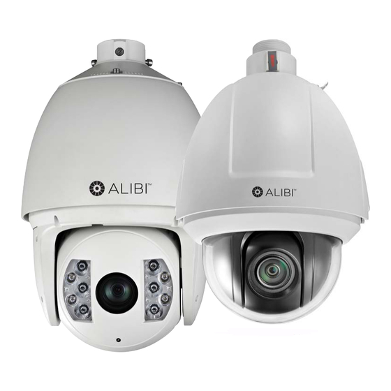
ALI-IPZ5030 Series IP PTZ Camera
Installation Guide
Products: ALI-IPZ5030T, ALI-IPZ5030RT
ALI-IPZ5030T Camera
ALI-IPZ5030RT Camera
PLEASE READ THIS MANUAL BEFORE USING YOUR CAMERAS, and always follow the instructions for safety
and proper use. Save this manual for future reference.
ALI-IPZ5030_CM
7/15/14
Advertisement
Table of Contents

Related Manuals for ALIBI ALI-IPZ5030T


Summary of Contents for ALIBI ALI-IPZ5030T
-
Page 1: Installation Guide
ALI-IPZ5030 Series IP PTZ Camera Installation Guide Products: ALI-IPZ5030T, ALI-IPZ5030RT ALI-IPZ5030T Camera ALI-IPZ5030RT Camera PLEASE READ THIS MANUAL BEFORE USING YOUR CAMERAS, and always follow the instructions for safety and proper use. Save this manual for future reference. ALI-IPZ5030_CM 7/15/14... - Page 2 ALIBI and the ALIBI logo are trademarks of Observint. Microsoft, Windows, and Internet Explorer are either registered trademarks or trademarks of Microsoft Corporation in the United States and/or other countries.
-
Page 3: Regulatory Information
SAFETY INSTRUCTIONS Regulatory information FCC information FCC compliance: This equipment has been tested and found to comply with the limits for a digital device, pursuant to part 15 of the FCC Rules. These limits are designed to provide reasonable protection against harmful interference when the equipment is operated in a commercial environment. - Page 4 If smoke, odors or noise rise from the device, turn off the power at once and unplug the power cable, and then please contact • the service center. If the product does not work properly, please contact your dealer or the nearest service center. Never attempt to disassemble •...
-
Page 5: Table Of Contents
2.1.1 Remove ALI-IPZ5030T packaging ........ - Page 6 TABLE OF CONTENTS...
-
Page 7: Overview
Congratulations on purchasing your new ALIBI™ IP PTZ camera! This installation guide includes procedures for installing and performing the initial setup of the ALI-IPZ5030T and ALI-IPZ5030RT cameras. Installation and operation of these cameras is identical. Differences between the two include the IR feature of the ALI-IPZ5030RT, and specification differences. -
Page 8: Features
SECTION 1: OVERVIEW 1.1 Features Limit Stops: The dome can be programmed to move within the limit stops (left/right, up/down). • Scan Modes: The dome provides five scan modes: auto scan, tilt scan, frame scan, random scan and panorama scan. •... -
Page 9: What's In The Box
Thread tape • Software and documentation CD • Quick installation guide (this document) • 1.3 Accessories The following accessories are available for the ALIBI ALI-IPZ5030T and ALI-IPZ5030RT cameras. Mounting bracket detail is shown below. Model Type ALI-PTZCL Ceiling Mount Bracket ALI-PTZWB... - Page 10 SECTION 2: NETWORK CONNECTION ALI-PTZCL: Ceiling Mount Bracket The Ceiling Mount Bracket is suitable for outdoor ceiling mounting. 2.24" 0.39" dia. (4) 4.57" dia. 3.52" dia.
- Page 11 SECTION 2: NETWORK CONNECTION ALI-PTZWB: Wall Mount Bracket The Wall Mount Bracket is suitable for indoor and outdoor wall mounting. 3.82" 12.2" 2.95" G 1.5" 0.33" dia. (4) ALI-IPZ5030 Series IP PTZ Camera Installation Guide...
- Page 12 SECTION 2: NETWORK CONNECTION ALI-PTZPM: Pole Mount PTZ Bracket The Pole Mount Bracket is suitable for outdoor pole mounting. The straps can attach to a 2.64” ~ 5.00” diameter pole. 3.94" dia. 5.63" 12.2" 4.61" G 1.5"...
- Page 13 SECTION 3: REMOTE ACCESS ALI-PTZCM: Corner Mount PTZ Bracket 16.52" 6.96" G 1.5" ALI-IPZ5030 Series IP PTZ Camera Installation Guide...
-
Page 14: Installation
SECTION 2: INSTALLATION SECTION 2 Installation Before you start Check the package contents and make sure that the device in the package is in good condition and all the assembly parts are • included: PTZ camera assembly — Pendant adapter — Thread tape —... -
Page 15: Remove The Packaging From The Camera
Lock screw screw Lower dome ALI-IPZ5030T camera assembly 2. Remove the lower dome and remove the protective foam and tape shown below. Be very careful not to touch the camera lens. Protective tape Protective foam Remove protective foam 3. Reattach the lower dome. -
Page 16: Remove Ali-Ipz5030Rt Packaging
SD card cannot provide camera log information, which is valuable for maintenance purposes. Your camera will accommodate an SD card with up to 32 GB of storage. The location of the SD card slot is different in the ALI-IPZ5030T and ALI-IPZ5030RT cameras. See below. SD card slot... -
Page 17: Camera Wall Mount Installation
SECTION 2: INSTALLATION Insert SD card into the ALI-IPZ5030T camera 1. Open the lower dome to access the dome drive. 2. Find the SD card slot near the camera lens. 3. Insert the SD card (up to 32 GB) until it is fully seated. - Page 18 SECTION 2: INSTALLATION Pendant adapter Bracket set screw Wrap with thread tape Loop for safety cable Pendant adapter Lock screw (2) Attach pendant adapter to mounting bracket 5. Screw the pendant adapter onto the end of the mounting bracket. Tighten the set screw to secure the adapter to the bracket. 6.
-
Page 19: Ceiling Mounting
SECTION 2: INSTALLATION 2.4 Ceiling mounting Following the instructions below to install the camera using the ALI-PTCL Ceiling Mount Bracket. 1. Determine the best mounting screws and hardware to anchor the mounting bracket with the camera to the mounting surface. Use the following guidelines: For cement ceiling mounting, use the expansion screw to anchor the bracket. -
Page 20: Connecting The Cables
SECTION 2: INSTALLATION 2.5 Connecting the cables Drop cables for the ALI-IPZ5030T and ALI-IPZ5030RT are the same. However, the power requirements for differ. Drop cable bundle Network (LAN) cable Audio cable Alarm Output cables Alarm Input cables RS-485 cable Video cable Power cable (24 Vac) Connect the camera to other devices as needed in the order shown below. - Page 21 SECTION 2: INSTALLATION Connect the Audio Out and ground wires to a line level audio receiver (impedance 600 Ω). Alarm inputs can be either normally open (N.O.) or normally closed (N.C.), configurable in the camera firmware. RS-485 cables Connect the RS-485 drop cable wires to an RS-485 or, or DVR/NVR with an RS-485 network interface for control of PTZ features. PTZ features can also be controlled through the camera network (browser) interface, and through a supported NVR PTZ control panel.
- Page 22 SECTION 2: INSTALLATION 4. Plug the power cable provided (not shown) into the back of the injector, then into a standard 120 Vac electrical outlet. When power is applied to the injector, the camera will power on and a system information display will appear for 2 minutes on top of the live video image from the camera.
-
Page 23: Configure Network Access
Step 1. Install the ALIBI Discover Tool The ALIBI Discover Tool is a software utility used to “discover” ALIBI cameras and NVRs/DVRs installed on the LAN and change their network settings. The tool is provided on the CD with your camera. To use the tool: 1. - Page 24 SECTION 3: CONFIGURE NETWORK ACCESS 5. To change the network settings of the camera to be compatible with the subnet where it is installed, do the following: a. Click the device to highlight it. Notice that the network parameters are shown in the right frame.
- Page 25 SECTION 3: CONFIGURE NETWORK ACCESS b. Modify the network settings to values compatible with the subnet where it is installed. c. Enter the admin password for the device in the password field. By default, the admin user password for ALIBI cameras is 1111.
-
Page 26: Remote Login
2. In the login window, enter your User Name and Password in the appropriate fields, then click Login. The default User Name and Password for ALIBI cameras is admin and 1111. 3. If this is the first time you are logging into the camera at this IP address AND you are using Internet Explorer 10 or newer, you must configure IE for Compatibility mode: a. - Page 27 SECTION 4: REMOTE LOGIN Tools icon b. In the Compatibility View Settings window, ensure that the IP address of your camera is in the Add this website field, then click Add. After clicking Add, the IP address will appear in the Websites list. Click Close. d.
- Page 28 SECTION 4: REMOTE LOGIN Otherwise, continue with step “4. In the Live View window shown below, click the PTZ button to open/close the PTZ control panel.” on page 23. e. In the message box, click Run to install WebComponents.exe. The following pop-up window will open. When this window appears, close the browser.
- Page 29 SECTION 4: REMOTE LOGIN g. Log into the camera again. A Live View display will appear. 4. In the Live View window shown below, click the PTZ button to open/close the PTZ control panel. ALI-IPZ5030 Series IP PTZ Camera Installation Guide...
-
Page 30: Additional Configuration Steps
5. In the PTZ control panel, click the manual control arrows to exercise the pan-tilt-zoom features of the camera. 4.1 Additional configuration steps Refer to the document ALIBI™ IP Camera Software User Manual provided on the software and documentation CD with your camera to customize the configuration of your camera. -
Page 31: Appendix A Specifications
APPENDIX A: SPECIFICATIONS APPENDIX A Specifications Product Specifications ALI-IPZ5030T ALI-IPZ5030RT Camera Image Sensor 1/2.8” CMOS Scanning Mode Progressive Scan Resolution Up to 1920 x 1080 Effective Pixels Approx. 2.1 Megapixel Minimum Illumination Color: 0.05 Lux (F1.6, AGC On) Color: 0.05 Lux (F1.6, AGC On) B/W: 0.005 Lux (F1.6, AGC On) - Page 32 APPENDIX A: SPECIFICATIONS Product Specifications ALI-IPZ5030T ALI-IPZ5030RT Audio Audio Streaming Two-way Audio Compression Format G.711u /G.711a /G.726 Pan and Tilt Smart Tracking Number of Presets Patrol 8 Patrols, Up to 32 presets per patrol Pattern 4 Patterns PTZ Position Display...
- Page 33 APPENDIX A: SPECIFICATIONS Product Specifications ALI-IPZ5030T ALI-IPZ5030RT Dimensions 12.02” H x 8.66” Φ 15.71” H x 9.65” Φ Operating Temperature High-PoE: -22°F ~ 149°F 24 Vac: -40°F ~ 149°F Operating Humidity 0% ~ 90% RH, Non-condensing Ingress Protection IP66 Color...
-
Page 34: Appendix B Lightning And Surge Protection
APPENDIX B: LIGHTENING AND SURGE PROTECTION APPENDIX B Lightning and Surge Protection This product includes TVS plate lightning protection technology to prevent damage caused by a pulse signal that is below 3000 watts from sources such as lighting, surging, etc. Protection measures must be taken to ensure electrical safety. The distance between signal transmission line and high-voltage equipment or high-voltage cable is at least 50 m. -
Page 35: Appendix C 24 Vac Wire Gauge And Transmission Distance
APPENDIX C: 24 VAC WIRE GAUGE AND TRANSMISSION DISTANCE APPENDIX C 24 Vac Wire Gauge and Transmission Distance The following table shows the recommended maximum distance adopted for the different wire sizes when the 24 Vac voltage loss is less than 10%. For the AC driven device, the maximum voltage loss rate allowable is 10%. For example, for a device with the rating power of 80 VA which is installed 35 feet (10 m) from the transformer, the minimum wire gauge required is 0.8000 mm. - Page 36 APPENDIX C: 24 VAC WIRE GAUGE AND TRANSMISSION DISTANCE Table 2. Wire Gauge Standards American Wire Gauge Cross-sectional Area of Bare Wire Gauge (mm) Bare Wire (mm 0.750 0.4417 0.800 0.5027 0.900 0.6362 1.000 0.7854 1.250 1.2266 1.500 1.7663 2.000 3.1420 2.500 4.9080 3.000 7.0683...
Need help?
Do you have a question about the ALI-IPZ5030T and is the answer not in the manual?
Questions and answers