Table of Contents
Advertisement
Advertisement
Table of Contents

Related Manuals for GE DVSR xU


Summary of Contents for GE DVSR xU
-
Page 1: User Manual
Security DVSR xU User manual P/N DVSR-xU_EN • REV2-23 • ISS 04MAR09... - Page 2 Disclaimer The information in this document is subject to change without notice. GE Security, Inc. (“GE Security”) assumes no responsibility for inaccuracies or omissions and specifically disclaims any liabilities, losses, or risks, personal or otherwise, incurred as a consequence, directly or indirectly, of the use or application of any of the contents of this document.
-
Page 3: Table Of Contents
Content Product overview ........................1 Product description ....................................1 Unpacking the DVSR xU and its accessories..........................1 Installation environment..................................2 DVSR xU installation .........................3 Connecting the devices ..................................3 Connecting alarm inputs and outputs............................4 Connecting the DVSR xU to a PC..............................4 Turning on the DVSR xU.................................. - Page 4 Overview of users and PINs................................77 Configuring the user settings................................78 12. System settings........................82 Capturing text insertions..................................83 Configuring the system settings..............................85 13. Troubleshooting and support....................94 Troubleshooting your system ................................94 Contacting technical support ................................95 Appendix 1: Specifications ......................96 DVSR xU Menu Map........................100...
-
Page 5: Product Overview
The DVSR xU offers 4, 8 or 16 channels of analog recording, all up to 4CIF resolution (704 x 576). The dual streaming functionality allows the user to set up different settings for recording and streaming video. -
Page 6: Installation Environment
Chassis: Other equipment may be placed on top of the DVSR xU if it weighs less than 16 kg. WARNING: Before installing the DVSR, please ensure that the power to the DVSR is switched off. -
Page 7: Dvsr Xu Installation
VGA output. Both outputs will display the same video information. Optional connections Connect a spot monitor (Mon B) to the DVSR xU. Connect the monitor video to VIDEO OUT. Connect the monitor audio (if used) to AUDIO OUT (). -
Page 8: Connecting Alarm Inputs And Outputs
Connect the external data and alarm input/output (I/O) cable. See Figure 3 on page 4 for more information. M. Connect the DVSR xU to ground. Power connection Connect the power cord to the DVSR xU. Be sure all devices are connected and turned on before you turn on the DVSR xU. Connecting alarm inputs and outputs Figure 3: Connecting the external data and alarm I/O cable : Not used... -
Page 9: Turning On The Dvsr Xu
To get the unit into operation quickly 1. Connect all the devices required to the back panel of the DVSR xU. See Figure 2 on page 3. 2. Turn on the unit. The unit automatically carries out a diagnostic test of the devices. The video images then appear onscreen. -
Page 10: Controlling The Dvsr Xu
DVSR xU User Manual Controlling the DVSR xU There are four ways to control the DVSR xU menu options: Front panel control IR remote control Mouse control Web browser control These options are described in the following sections. -
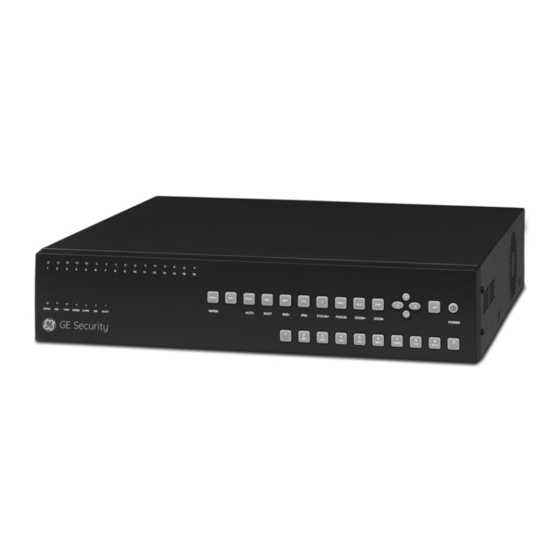
Page 11: Using The Front Panel
- If the PTZ option is activated, the arrows control the PTZ camera. - Control the playback video. C. POWER Power switch. Press the button for at least 5 seconds to turn off the DVSR xU. You will be asked for your PIN. D. Alphanumeric Select video channels. - Page 12 F. Status Status: Green indicates that the unit is linked to an IR remote control. HDD: Red indicates that the DVSR xU is accessing the HDD. TX/RX: Flashing green indicates data transmission. Modem: Green indicates that the unit is currently connected to a network.
-
Page 13: Using The Ir Remote Control
2. Enter the device ID. The DVSR xU default ID is 1. Note: See page 31 on how to change the device ID. 3. Press OK. The Status LED will light up on the DVSR xU front panel. To switch off the IR remote control 1. -
Page 14: Using The Mouse
If the problem persists, please contact your local supplier. Using the mouse Use the USB mouse provided with the DVSR xU. It can carry out the same operations as the front panel and remote control. Connect the mouse to the DVSR by simply plugging the mouse USB connector into the USB port on the back of the DVSR xU. -
Page 15: Using The Web Browser
Using the Web browser The DVSR xU Browser lets you easily view, record, and playback video as well as manage all aspects of the system from any Internet location. It has easy-to-use controls that give you quick access to the functions you require. -
Page 16: Basic Operations
The way the monitors display video depends on how you set up the system. In live mode, the DVSR xU displays the status of each video channel at the bottom of the screen. See Figure 8. The number of channels displayed (4, 8, or 16) depends on the DVSR xU model. - Page 17 If the letter is grey letter, the monitor is inactive Caution: DVSR xU has no camera autodetection mode. The unit records a channel even if no camera is connected to it. A black picture with the message "Video Loss" is displayed when the channel is selected in either live mode or playback mode.
-
Page 18: Selecting Live View
Mouse Right-click the mouse and select Swap Monitor from the menu shown. To view a full screen display Front panel/ DVSR xU with 4 or 8 Press the number button that corresponds to the camera number. remote control cameras: For example, press button 2 to preview camera number 2. -
Page 19: Manual Recording
DVSR xU User Manual To view a multiscreen display Front panel/remote control Press the PREV button to switch to multiscreen live viewing. If the multiscreen display does not include all the cameras you want to see, keep pressing the PREV button to increase the number of screens displayed. -
Page 20: Searching And Playing Back Recorded Video
DVSR xU User Manual To manually start or stop a recording 1. Press the REC button on the front panel of the DVSR or the IR remote control, or right-click the mouse, and select Manual Record. Enter your user name and PIN, if requested. - Page 21 To search for recorded video 1. In live mode press the PLAY button on the front panel of the DVSR xU or the IR remote control, or right-click the mouse and select Search. Enter your user name and PIN, if requested. The playback menu appears.
- Page 22 DVSR xU User Manual 5. If you want to search for video from a particular ATM, for example, go to Text and press Enter or left-click the mouse to activate (). In the edit box alongside the check box type the text to be searched (for example, the text that appears on an ATM screen.)
-
Page 23: Archiving Recorded Files
DVSR xU User Manual 3. Press ESC or right-click the mouse to return to the Play Back menu. All the files you selected for playback are now deselected. 4. Press ESC again or right-click the mouse to quit playback mode and return to live view. - Page 24 DVSR xU User Manual Figure 17: Playback information on a recorded file Audio Playback progress Playback speed Current playback Total playback time time Press PLAY to Shows how far you Press the arrow buttons Playback always Shows the duration of...
- Page 25 DVSR xU User Manual 2. Search for the recorded files you want to copy. See To search for recorded video on page 17 for more information. 3. Press the EDIT button or left-click the mouse to select the video file you want to copy from the list.
- Page 26 8. Go to the Set Today’s Time edit boxes and enter the period of time during the day to be archived. Note: Time has a 24-hour format. 9. Go to the Archiving Delay list box and select the time after activating the DVSR xU for auto backup to start.
- Page 27 DVSR xU User Manual To archive all recorded files found in a search 1. Press the PLAY button, or right-click the mouse and select Search. Enter your user name and PIN, if requested. The playback menu appears. See Figure 20.
-
Page 28: Controlling A Ptz Camera
DVSR xU User Manual Figure 21: Playback tool bar 5. When you reach the part of the playback that you want to copy, press EDIT to start copying. A red radio button appears in the right hand corner of the screen when copying is taking place. -
Page 29: Control Icons
DVSR xU User Manual Figure 22: PTZ control Table 4 Description of the PTZ control buttons DVSR front panel IR remote control Onscreen PTZ Description control icons Pan left/right and tilt up/down. Zoom in (+) and out (-). INFO VOIP... -
Page 30: Overview Of The Menu Structure
Overview of the menu structure The DVSR xU has an icon driven menu structure that allows you to configure the unit’s parameters. Figure 23 shows the DVSR xU main menu screen. Each icon symbolizes the content of the submenu. - Page 31 Configures the alarm input type, alarm rules, alarm output type, PTZ linkage, notification settings. See section Alarm on page 63. Configures the RS-485, PTZ protocols, and PTZ addresses. Comprehensive configuration of GE domes, and basic setup of non-GE devices. See section PTZ on page 69.
-
Page 32: Changing The Menu Settings
You will return to the main menu screen. Changing the menu settings The DVSR xU is delivered with default settings that can be easily changed from the menus. Caution: If there is a power failure, you will loose all user-modified settings. The systems will return to... -
Page 33: Turning Off The Dvsr Xu
Note: If you turn off the power by pressing the POWER button on the front panel, and the PIN enable option has been enabled in the Display menu (page 32), you will need to enter your PIN before the DVSR xU will turn off. -
Page 34: Display Settings
DVSR xU User Manual Display settings Use the Display menu to configure which information is displayed onscreen and how it should look. The following options can be configured: The language of the unit The device ID If a PIN is required ... -
Page 35: Configuring The Display Settings
To change the DVSR xU’s bus ID When you use the IR remote control to operate the DVSR xU, the DVSR xU must have a device ID. The default device ID is “01“. If there is more than one DVSR used, each unit must have its own unique... - Page 36 To setup the PIN requirement A PIN is required by default to access the DVSR xU. See section To modify a user’s PIN on page 78 for information on PINs. 1. In the Display menu go to the Log In PIN Required check box and press Enter or left-click the mouse to enable or disable it ().
- Page 37 To set the system time and date You can setup the DVSR xU date and time as well as the Daylight Saving Time (DST). This is the date and time that will appear on screen. You can setup when DST for the DVSR starts and stops in the year.
- Page 38 2. Go to the Monitor Output list box. Select between monitor output A or B. Monitor A is default. 3. Go to the Display list box. Select the desired multi screen mode from the drop-down list. Table 7: Multi screen options available Number of DVSR xU channels Multi screen options 1 screen...
- Page 39 DVSR xU User Manual For example: If a 16-channel DVSR xU has the 4-screen live mode and the 20-second switch time mode selected, the DVSR xU will cycle four camera displays every 20 seconds. 5. Go to the Audio check box and press EDIT or left-click the mouse to enable ().
-
Page 40: Camera Settings
DVSR xU User Manual Camera settings Use the Camera menu to configure the cameras. The following options can be configured: The name of each camera The position of the camera name on screen The camera brightness, contrast, saturation and hue ... -
Page 41: Configuring Camera Settings
DVSR xU User Manual Configuring camera settings The following procedures show how to change camera settings from the Camera menu. They can be changed in any order. In the main menu, go to the Camera menu icon and press Enter or left-click the mouse. The Camera menu appears. - Page 42 DVSR xU User Manual To adjust the image quality of the camera video Different cameras and backgrounds may need to have the screen image modified in order to obtain the best video image. Use this menu to configure the video image. You can setup each camera separately or copy the video parameters of one camera to another camera.
- Page 43 DVSR xU User Manual To setup a camera’s displayed time and date 1. In the Camera menu select the camera you want to adjust. 2. Go to the Time & Date list box and press Enter or left-click the mouse to select the display mode required.
- Page 44 Enter, or right-click the mouse and select OK, to return to the Camera menu. To setup the DVSR xU to respond to a motion detection alarm The DVSR can be setup to trigger an alarm if a camera detects motion. You can select the level of sensitivity to motion, where on screen the motion can be detected, and specify which cameras can record the motion when a motion alarm is detected.
- Page 45 DVSR xU User Manual 2. To select the motion detection zone(s) a. Go to the Zone setup button and press EDIT or left-click the mouse. The Motion Zone setup screen appears. See Figure 31. Figure 31: The Motion Zone setup screen There is a solid white pane onscreen.
- Page 46 DVSR xU User Manual Figure 32: Example of motion detection zones e. To clear part of a motion detection zone, move the solid white square to the motion detection zone that you want to delete. Press EDIT. The white pane becomes transparent. Use the arrow keys to increase or decrease the size of the black zone.
- Page 47 This is done in the Recording menu. See page 53 for more information. c. Go to Alarm Schedule and select when you want the DVSR xU to respond to a motion alarm. You can select up to seven days in a week and up to four time periods for each a day.
- Page 48 DVSR xU User Manual To setup a privacy mask You can mask a sensitive area on screen so that it remains hidden from view. An example would be when the view of a camera overlooks onto residential premises. The area hidden by the privacy mask will not be viewed live nor recorded, but will appear as a blank area on screen.
- Page 49 DVSR xU User Manual 4. Use the arrow buttons to move the white pane to the zone on screen that you want to mask. Press EDIT or left-click the mouse to select the first square. The pane turns transparent. The transparent pane indicates the zone that will be masked.
- Page 50 Go to Period 1 and enter the time period for the response. You can set up to four time periods for each day of the week. You must reboot the DVSR xU to make the time periods operational. Note: The daily time periods cannot overlap.
- Page 51 DVSR xU User Manual Table 11: Notification options on how to respond to a camera tamper alarm Notification option Reponse Alarm Out Alarm Out is activated. Up to four alarm outputs can be enabled. Buzzer An audible alarm sounds TCP...
- Page 52 5. Go to the notification options and press Enter or left-click the mouse to enable () or disable how you want the DVSR xU to respond to a video loss tamper alarm. See Table 12. Table 12: Notification options on how to respond to a video loss tamper alarm...
-
Page 53: Recording Settings
DVSR xU User Manual Recording settings Use the Recording menu to setup how the DVSR xU records information. The following options can be configured: Handling information when the HDD is full eSATA record or backup Auto deletion ... - Page 54 No Overwrite When all the HDDs in the DVSR xU are full, the DVSR will handle the event as a “Hard Disk Full” condition and respond according to how this condition has been programmed under the...
- Page 55 You can use an external storage device, such as an e-SATA HDD, as a backup for video or add its recording capacity to that of the DVSR xU itself. If you change this option, you must reboot the DVSR xU to implement the change.
- Page 56 Event Records all alarms. 4. To select audio and/or video recording You can select whether the recording is video only (default), or audio and video. If you change this option, you must reboot the DVSR xU to implement the change.
- Page 57 DVSR xU User Manual Go to the Stream Type list box and select one of the two options: Option Description Audio&Video Records both audio and video. Video Records video only. 5. To change the camera resolution You can select one of four video resolutions. A high image resolution requires that a high bit rate must also be selected.
- Page 58 (see section To setup an external alarm output on page 67). The DVSR xU is recording all the time at a defined rate. The prerecording time is the time before a motion or external alarm is triggered and which is included in the alarm data. It is related to the bit rate.
- Page 59 1. Go to the Copy to Camera list box and select one of the cameras listed. 2. Go to Copy press Enter or left-click the mouse. 3. DVSR xU will ask you if you want to copy the current camera settings to another Camera. Select OK or Cancel.
-
Page 60: Network Settings
DVSR xU User Manual Network settings Use the Networking menu to setup the network settings of the DVSR xU. The following options can be configured: IP address and settings Subnet mask Gateway IP DNS address ... -
Page 61: Configuring The Network Settings
To change the DNS address value If DVSR uses a PPPoE function, the DVSR xU can get a dynamic IP address. If you set DNS IP with a fixed Internet IP, DVSR xU will send information such as its name, serial number, and current IP to that fixed IP address. - Page 62 DVSR xU User Manual 1. In the Network menu go to the DNS edit box and press EDIT or left-click the mouse. Using the numeric buttons enter the DNS number. Press Enter or left-click the mouse to accept the changes.
- Page 63 1. In the Network menu go to the Advanced Settings setup box and press Enter or left-click the mouse. The Advanced Settings submenu appears. See Figure 43. The MAC Address edit box shows the MAC address of the DVSR xU unit.
- Page 64 Note: Use the FTP IP if the PPPoE function is being used, and the DVSR xU gets a dynamic IP address from the ISP. If you set the FTP IP you will get one fixed Internet IP, DVSR xU will send information such as its name, serial number, and current IP to that fixed IP address.
- Page 65 9. Go to the Time Zone edit boxes and set the time zone in which the DVSR xU is located. 10. Go to the Interval edit box and enter the number of hours after which the DVSR xU should synchronize its time with that of the network server.
- Page 66 DVSR xU User Manual To setup DDNS 1. In the Network menu go to the DDNS edit box and press Enter or left-click the mouse. The DDNS submenu appears. See Figure 44. Figure 44: DDNS submenu 2. Go to the DDNS check box and press EDIT or left-click the mouse to enable () or to disable the option.
-
Page 67: Alarm Settings
DVSR xU User Manual Alarm settings Use the Alarm menu to setup how the DVSR xU handles alarms. You can select how the alarm settings should be handled such as: An external alarm input An internal alarm input ... -
Page 68: Configuring The Alarm Settings
DVSR xU User Manual When setting up the alarm relay output, you need to set the alarm output time delay. This delay is the time that the alarm output continues after the alarm itself has been deactivated. Consequently the actual alarm output time consists of the alarm input time and alarm output time delay. - Page 69 See section To setup a camera’s recording schedule on page 53 for further information. c. Under Alarm Schedule select the schedule for when the DVSR xU will respond to an external alarm. Select the day of the week and then for Period 1 enter the start and end time periods for the selected day.
- Page 70 DVSR xU User Manual 5. To set a PTZ link to the alarm a. In the Alarms menu go to the Link PTZ setup button and press Enter or left-click the mouse. The Link PTZ submenu appears. See Figure 47.
- Page 71 Acknowledge: The alarm output will not stop until the menu option Alarm Output Stop is activated in the System menu. See page 93 for further information. Caution: An alarm can only be acknowledged locally. Do not select this option if the DVSR xU is controlled over a network.
- Page 72 DVSR xU User Manual 4. Select the day of the week and then for Period 1 enter the start and end time periods for the selected day. Each day can have up to four time periods. Note: The time format is 24-hour.
-
Page 73: 10. Ptz Settings
DVSR xU User Manual 10. PTZ settings You can control the PTZ functions of the cameras connected to the DVSR xU. The PTZ menu allows you to setup the RS-285 and PTZ parameters to match your PTZ protocol such as: ... -
Page 74: Description Of Preset, Preset Tour, And Shadow Tour Options
Before the PTZ cameras are assembled in their housings, set their protocol and address DIP switches for the DVSR xU. See Table 19 for the different GE Security’s PTZ camera configurations. If you are using PTZ cameras from another company, please refer to their configuration instructions. -
Page 75: Configuring The Ptz Settings
DVSR xU User Manual Camera Switch setting CyberDome II Protocol switches 0000 Address switches: 0000 Legend Protocol switches Address switches: 0000 Configuring the PTZ settings The following procedure shows how to change the PTZ menu settings. They can be changed in any order. - Page 76 1. In the PTZ menu set up the Baud Rate, Data Bits, Stop Bits, Parity, and Flow Ctrl. For each one in turn, select the required configuration as provided by the dome manufacturer. For example, the configuration for GE Security is: (default) ...
- Page 77 DVSR xU User Manual 1. In the PTZ menu go to the Preset setup button and press Enter or left-click the mouse. The Set Preset submenu appears. See Figure 50. Figure 50: The PTZ Set Preset submenu 2. Select the Preset setup button and press EDIT or left-click the mouse. Enter your preset number (between 1 and 16) and press Enter or left-click the mouse to accept.
- Page 78 DVSR xU User Manual To tour the preset positions You can tour all preset positions in a camera. First you need to save the steps of preset positions to include in a tour. 1. In the PTZ menu go to the Preset Tour setup box and press Enter or left-click the mouse. The Sequence submenu appears.
- Page 79 DVSR xU User Manual To setup a ShadowTour 1. In the PTZ menu go to the ShadowTour setup button and press Enter or left-click the mouse. The Shadow Tour submenu appears. See Figure 52. Figure 52: The PTZ Sequence submenu screen 2.
-
Page 80: 11. User Settings
DVSR xU User Manual 11. User settings This section describes how to Change user PINs Add new users Add or modify operational rights of users The User icon is located in the main menu. The following screen appears when you select the... -
Page 81: Overview Of Users And Pins
However, once you have completed the installation and setup you should change the admin PIN to protect against unauthorized access. Caution: Keep the Admin PIN in a safe place. If you should forget it, you must return the DVSR xU unit to our service center to be reconfigured. -
Page 82: Configuring The User Settings
To modify a user’s PIN PINs are used to limit access to the DVSR xU. Only the administrator can create or delete a PIN. The same PIN can be used by several users. When you create a new user, the default PIN is 0000. - Page 83 DVSR xU User Manual Figure 54: The add user dialog box Using the alphanumeric buttons, enter the new user name (see Table 6 on page 29 for how to enter characters) and press Enter to confirm. The user menu appears with the new name listed.
- Page 84 To setup a MAC address The MAC address is not the DVSR xU address but that of the PC which will access the DVSR xU. If you setup a MAC address, only the PC with that MAC address can access the DVSR xU.
- Page 85 DVSR xU User Manual Figure 56: User’s MAC address 3. Go to the User’s MAC Addr. and press EDIT or left-click the mouse. Use the number buttons to enter t the MAC address. Press Enter to accept the entry if using the front panel or remote control.
-
Page 86: 12. System Settings
DVSR xU User Manual 12. System settings The System menu allows you to setup the following parameters such as: Handle transaction information Configure RS-232 settings Upgrade the firmware Restore factory defaults Reboot the DVSR xU ... -
Page 87: Capturing Text Insertions
Figure 57: The system configuration screen Capturing text insertions The DVSR xU can actively obtain or passively receive text information from other devices linked through a network or a serial port. This information can then be overlaid on live video, recorded, and played back. - Page 88 To setup the DVSR xU, you need to enter the following information: ATM through the serial port Type of ATMS machine Transaction type and code Software must be run in the ATM to send the command to the DVSR xU through the RS-232 port.
-
Page 89: Configuring The System Settings
DVSR xU User Manual Configuring the system settings The following procedure shows how to specify system parameters. The options can be changed in any order. In the main menu, go to the System menu icon and press Enter or left-click the mouse. The System menu appears. - Page 90 Receive data sent by ATM through serial port: Go to the Protocol list box and select the protocol parameter. GE ProBridge is default. Go to the Start String edit box and press EDIT or left-click the mouse to enter edit mode. Enter the values. Select OK when completed and...
- Page 91 The following procedure shows how to change the RS-232 settings from the RS-232 submenu. The pre-populated default values are for GE ProBridge. The RS-232 settings can be changed in any order. 1. In the System menu go to the RS-232 setup box and press Enter or left-click the mouse. The RS-...
- Page 92 232 port to a PC serial port for HyperTerminal control. For the text insert mode, connect serial devices such as ATM machines or GE ProBridge for point-of-service (POS) systems. 3. Select OK to accept the changes and return to the System menu.
- Page 93 Press ESC, or right-click the mouse, to cancel. If you select the USB mode, you must connect a USB flash memory to the DVSR xU and confirm that the firmware file is in the root directory. Press Enter or left-click the mouse to start the upgrade.
- Page 94 3. To format the HDD Caution: Before formatting the HDD, stop all recording. Once formatting is completed, you must reboot DVSR xU as otherwise the unit will not function correctly. a. Go to the HDD list box and select the HDD required.
- Page 95 DVSR xU User Manual Sub information types. There are several different types of sub information depending on the main type selected. See Table 24. Table 24: Sub information types by main type Main information types Sub information types Alarm...
- Page 96 5. To search for the logs Go to the Search Log button and press Enter or left-click the mouse to start the search. When the search is completed, the DVSR xU will list all matched log information in the window underneath.
- Page 97 Note: If you turn off the power by pressing the POWER button on the front panel, and the PIN enable option has been enabled in the Display menu (see page32), you will need to enter your PIN before the DVSR xU will turn off.
-
Page 98: 13. Troubleshooting And Support
13. Troubleshooting and support This section provides information to help you diagnose and solve various problems that may arise while configuring or using your GE Security product and offers technical support contacts in case you need assistance. Troubleshooting your system... -
Page 99: Contacting Technical Support
DVSR xU User Manual Contacting technical support For assistance installing, operating, maintaining, and troubleshooting this product, please contact your local supplier. Our web address is: www.gesecurity.eu Note: Be ready at the equipment before calling for technical support. -
Page 100: Appendix 1: Specifications
DVSR xU User Manual Appendix 1: Specifications Video compression MPEG-4AVC (H.264) PAL: 704 x 576, Live resolution NTSC: 704 x 480 Playback resolution QCIF/CIF/2CIF/4CIF Video input 4/8/16 Video input interface BNC (Electrical Level: 1.0 Vp-p, resistance: 75 Ω) Monitor A: One monitor A multiscreen output, BNC connector, NTSC/EIA... - Page 101 DVSR xU User Manual...
- Page 103 DVSR xU User Manual...
-
Page 104: Dvsr Xu Menu Map
DVSR xU Menu Map See page 30 See page 36 See page 49 See page 56 See page 63 See page 69 See page 76 See page 82...
Need help?
Do you have a question about the DVSR xU and is the answer not in the manual?
Questions and answers