Sony DCR-TRV820 Service Manual
Digital video cassette recorder digital 8
Hide thumbs
Also See for DCR-TRV820:
- Operating instructions manual (156 pages) ,
- Limited warranty (1 page) ,
- Operating instructions manual (156 pages)
Table of Contents
Advertisement
DCR-TRV820/TRV820E/TRV820P
SERVICE MANUAL
Ver. 1.0 2000. 04
TM
B700 MECHANISM
NTSC MODEL : DCR-TRV820/TRV820P
PAL MODEL
: DCR-TRV820E
When the machine needs to be repaired,
please refer to page 8 to discriminate the
type of LCD.
Video camera
recorder
System
Video recording system
2 rotary heads
Helical scaning system
Audio recording system
Rotary heads, PCM system
Quantization: 12 bits (Fs 32 kHz,
stereo 1, stereo 2), 16 bits
(Fs 48 kHz, stereo)
Video signal
DCR-TRV820/TRV820P :
NTSC color, EIA standards
DCR-TRV820E :
PAL colour, CCIR standards
Recommended cassette
Hi8/Digital8 video cassette
Recording/Playback time (using
120 min. Hi8 video cassette)
SP mode: 1 hour
LP mode: 1 hour and 30 minutes
Fastforward/rewind time (using
120 min. Hi8 video cassette)
Approx. 5 min.
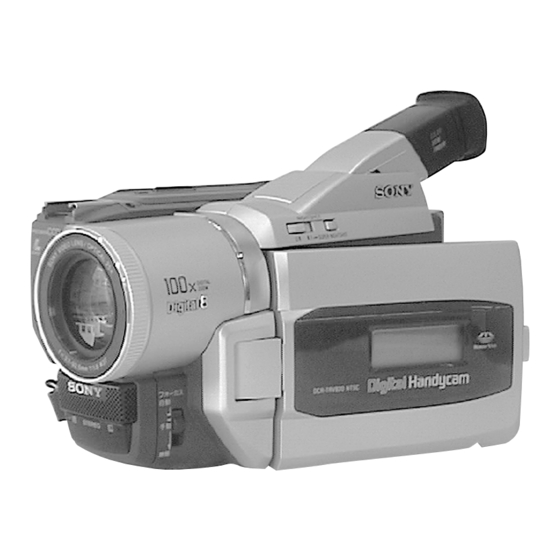
Photo: DCR-TRV820E
SPECIFICATIONS
Viewfinder
Electric Viewfinder (colour)
Image device
1/4 type CCD (Change Coupled
Device)
DCR-TRV820/TRV820P :
Approx. 460,000 pixels
(Effective: Approx. 290,000 pixels)
DCR-TRV820E :
Approx. 800,000 pixels
(Effective: Approx. 400,000 pixels)
Lens
Combined power zoom lens
Filter diameter 37 mm (1 1/2 in.)
25× (Optical)
DCR-TRV820/TRV820E: E, AUS, CN,
JE/TRV820P :
450× (Digital)
DCR-TRV820E: AEP, UK :
100× (Digital)
Focal length
3.7 - 92.5 mm (5/32 - 3 3/4 in.)
When converted to a 35 mm still camera
48 - 1200 mm (1 15/16 - 47 1/4 in.)
Colour temperature
Auto
DIGITAL VIDEO CASSETTE RECORDER
For MECHANISM ADJUSTMENT, refer to
the "8mm Video MECHANICAL
ADJUSTMENT MANUAL
Minimum illumination
DCR-TRV820/TRV820P :
1 lux (F 1.6)
DCR-TRV820E :
3 lux (F 1.6)
0 lux (in the NightShot mode)*
* Objects unable to be seen due to the
dark can be shot with infrared
lighting.
Input/output
connectors
DCR-TRV820/TRV820P :
S video input/output
4-pin mini DIN
Luminance signal: 1 Vp-p,
75 ohms, unbalanced
Chrominance signal: 0.286 Vp-p,
75 ohms, unbalanced
Audio/Video input/output
AV MINIJACK, 1 Vp-p, 75 ohms,
unbalanced, sync negative
327 mV, (at output impedance more than
47 kilohms)
Output impedance with less than 2.2
kilohms/Stereo minijack (ø 3.5 mm)
Input impedance more than 47 kilohms
DCR-TRV820E :
RMT-814
US Model
Canadian Model
DCR-TRV820
AEP Model
UK Model
DCR-TRV820E
E Model
DCR-TRV820/TRV820E/TRV820P
Korea Model
DCR-TRV820
Australian Model
Chinese Model
DCR-TRV820E
Tourist Model
DCR-TRV820/TRV820E
" (9-973-801-11).
S video input/output
4-pin mini DIN
Luminance signal: 1 Vp-p,
75 ohms, unbalanced
Chrominance signal: 0.3 Vp-p,
75 ohms, unbalanced
Audio/Video output
AV MINIJACK, 1 Vp-p, 75 ohms,
unbalanced, sync negative
327 mV, (at output impedance more than
47 kilohms)
Output impedance with less than 2.2
kilohms/Stereo minijack (ø 3.5 mm)
DV input/output
4-pin connector
Headphone jack
Stereo minijack (ø 3.5 mm)
LANC
/DIGITAL I/O jack
Stereo mini-minijack (ø 2.5 mm)
Transfer rate: Max 115.2 Kbps
RS-232C based
MIC jack
Stereo minijack (ø 3.5 mm)
– Continued on next page –
Advertisement
Table of Contents

Related Manuals for Sony DCR-TRV820


Summary of Contents for Sony DCR-TRV820
- Page 1 Australian Model Chinese Model DCR-TRV820E Photo: DCR-TRV820E Tourist Model B700 MECHANISM DCR-TRV820/TRV820E NTSC MODEL : DCR-TRV820/TRV820P For MECHANISM ADJUSTMENT, refer to PAL MODEL : DCR-TRV820E the “8mm Video MECHANICAL ADJUSTMENT MANUAL ” (9-973-801-11). When the machine needs to be repaired, please refer to page 8 to discriminate the type of LCD.
-
Page 2: Battery Pack
DE FONCTIONNEMENT. NE REMPLACER CES COM- SONY PARTS WHOSE PART NUMBERS APPEAR AS SHOWN IN THIS MANUAL OR IN SUPPLEMENTS PUB- POSANTS QUE PAR DES PIÈCES SONY DONT LES LISHED BY SONY. NUMÉROS SONT DONNÉS DANS CE MANUEL OU DANS LES SUPPLÉMENTS PUBLIÉS PAR SONY. - Page 3 Supplied accessories 1 Wireless Remote Commander (1) qa 2-pin conversion adaptor (1) 2 AC-L10A/L10B/L10C AC Power adaptor (1), DCR-TRV820: JE/TRV820E: JE Mains lead (1) qs Carrying bag (1) 3 NP-F330 battery pack (1) DCR-TRV820P 4 CR2025 lithium battery (1) qd PC serial cable (1) qf “Memory Stick”...
-
Page 4: Table Of Contents
TABLE OF CONTENTS Section Title Page Section Title Page SERVICE NOTE Viewing a Still Image – Memory Photo Playback ........... 1-28 Power Supply During Repairs ........7 Copying the Image Recorded on To Take Out a Cassette “Memory Stick” to Tapes ............1-29 When Not Eject (Force Eject) ........ -
Page 5: Title
Section Title Page Section Title Page VC-235 (CAMERA PROCESSOR) 1-1-1. List of Service Tools ..........5-4 Schematic Diagram ............ 4-15 1-1-2. Preparations ............5-6 VC-235 (Y/C PROCESSOR) 1-1-3. Precaution ............. 5-8 Schematic Diagram ............ 4-17 1. Setting the Switch ..........5-8 VC-235 (LENS MOTOR DRIVE) 2. - Page 6 Section Title Page Section Title Page 3-1-1. Equipment to Required ......... 5-36 7. Record of Use Check ..........5-63 3-1-2. Precautions on Adjusting ........5-37 8. Switch Check (1) ........... 5-63 3-1-3. Adjusting Connectors ..........5-38 9. Switch Check (2) ........... 5-64 3-1-4.
-
Page 7: Service Note
SERVICE NOTE POWER SUPPLY DURING REPAIRS In this unit, about 10 seconds after power is supplied (8.4 V) to the battery terminal using the service power cord (J-6082-223-A), the power is shut off so that the unit cannot operate. This following two methods are available to prevent this. Take note of which to use during repairs. -
Page 8: Note For Repair
NOTE FOR REPAIR When remove a connector, don’t pull at wire of connector. It is possible that a wire is snapped. Make sure that the flat cable and flexible board are not cracked of bent at the terminal. Do not insert the cable insufficiently nor crookedly. When installing a connector, don’t press down at wire of connector. -
Page 9: Self-Diagnosis Function
SELF-DIAGNOSIS FUNCTION Self-diagnosis Display Self-diagnosis Function When problems occur while the unit is operating, the self-diagno- When problems occur while the unit is operating, the counter of sis function starts working, and displays on the viewfinder or Dis- the viewfinder or Display window shows a 4-digit display consist- play window what to do. -
Page 10: Self-Diagnosis Code Table
Self-diagnosis Code Table Self-diagnosis Code Block Detailed Symptom/State Correction Function Code Condensation. Remove the cassette, and insert it again after one hour. Video head is dirty. Clean with the optional cleaning cassette. Non-standard battery is used. Use the InfoLITHIUM battery. LOAD direction. - Page 11 Self-diagnosis Code Block Detailed Symptom/State Correction Function Code Inspect the lens block focus reset sensor (Pin 9 of CN1551 of VC-235 board) when focusing is performed when the control dial Difficult to adjust focus is rotated in the focus manual mode and the focus motor drive circuit (Cannot initialize focus.) (IC1553 of VC-235 board) when the focusing is not performed.
-
Page 12: General
Русский Welcome! Добро пожаловать! accessories принадлежностей Congratulations on your purchase of this Sony Make sure that the following accessories are Digital Handycam camcorder. With your Digital supplied with your camcorder. Handycam, you can capture life’s precious moments with superior picture and sound quality. -
Page 13: Using This Manual
— Подготовка к эксплуатации — Использование данного Использование — Getting started — Using this manual руководства Using this manual данного руководства Note on TV colour systems Примечание по системам The instructions in this manual are for the two цветного телевидения TV colour systems differ from country to models listed in the table below. - Page 14 Step 1 Preparing the power Step 1 Preparing the power Пункт 1 Подготовка источника Пункт 1 Подготовка источника supply питания supply питания After charging the battery pack После зарядки батарейного блока Charging the battery pack Зарядка батарейного блока Disconnect the AC power adaptor from the DC IN jack on your camcorder.
-
Page 15: Step 2 Inserting A Cassette
Что такое “InfoLITHIUM”? camcorder operates only with the “InfoLITHIUM” battery. “InfoLITHIUM” battery packs have the mark. “InfoLITHIUM” is a trademark of Sony Corporation. PRECAUTION ПРЕДОСТЕРЕЖЕНИЕ The set is not disconnected from the AC power source (the mains) as long as it is connected to the mains, even if the set itself has been turned off. -
Page 16: Recording A Picture
— Recording – Basics — — Запись – Основные положения — Recording a picture Запись изображения Recording a picture Запись изображения Your camcorder automatically focuses for you. Notes Примечания (1) Remove the lens cap by pressing both knobs •Fasten the grip strap firmly. on its sides and attach the lens cap to the grip •Do not touch the built-in microphone during strap. - Page 17 Recording a picture Recording a picture Запись изображения Запись изображения Notes on digital zoom Indicators displayed in the Примечания к наезду видеокамеры Индикаторы, отображаемые в •Digital zoom starts to function when zoom цифровым методом recording mode режиме записи exceeds 25×. •The picture quality deteriorates as you go The indicators are not recorded on tape.
-
Page 18: Checking The Recording
Recording a picture Recording a picture Запись изображения Запись изображения Notes Примечания Self-timer recording Запись по таймеру самозапуска •Do not use the NightShot function in bright Recording with the self-timer starts in 10 seconds places (ex. outdoors in the daytime). This may cause your camcorder to malfunction. -
Page 19: Playing Back A Tape
— Воспроизведение – Основные положения — Воспроизведение — Playback – Basics — Playing back a tape Воспроизведение ленты Playing back a tape ленты When monitoring on the LCD screen Во время контроля на экране ЖКД You can turn the LCD panel over and move it You can monitor the playback picture on the back to the camcorder body with the LCD screen LCD screen. -
Page 20: Viewing The Recording On Tv
Your camcorder consumes power. Press S.LASER передачи сигналов (при этом Super laser link emitter/ высвечивается кнопка S.LASER LINK) LINK to turn off the super laser link function Излучатель лазерного суперканала when it is not needed. is a trademark of Sony Corporation... -
Page 21: Recording A Still Image On A Tape - Tape Photo Recording
— Advanced Recording Operations — — Усовершенствованные операции съемки — Recording a still image on a tape Запись неподвижного изображения Recording a still image on a Запись неподвижного изображения – Tape Photo recording на ленту – фотосъемка на ленту tape – Tape Photo recording на... -
Page 22: Using The Wide Mode
Using the fader Использование Использование Using the wide mode function широкоэкранного режима функции фейдера You can record a 16:9 wide picture to watch on You can fade the picture in or out to give your the 16:9 wide-screen TV (16:9WIDE). recording a professional appearance. -
Page 23: Using Special Effects - Picture Effect
Использование Using special effects Использование специальных Using special effects специальных эффектов – Picture effect эффектов – Эффект изображения – Picture effect – Эффект изображения (1) Press PICTURE EFFECT in CAMERA mode. The picture effect indicator appears. You can digitally process images to obtain special (2) Turn the SEL/PUSH EXEC dial to select the effects like those in films or on the TV. -
Page 24: Using The Program Ae Function
Using the PROGRAM Использование Using special effects – Digital Использование специальных AE function функции PROGRAM AE effect эффектов – Цифровой эффект To cancel the digital effect Для отмены цифрового эффекта You can select PROGRAM AE (Auto Exposure) Вы можете выбрать режим PROGRAM AE mode to suit your specific shooting requirements. -
Page 25: Focusing Manually
Focusing manually Фокусировка вручную Focusing manually Фокусировка вручную You can gain better results by manually adjusting Вы можете получить лучшие результаты путем To focus precisely Для точной фокусировки the focus in the following cases: регулировки вручную в следующих случаях: Adjust the zoom by first focusing at the “T” Отрегулируйте... -
Page 26: Making Your Own Titles
Making your own Создание Ваших Создание Ваших собственных titles собственных титров Making your own titles титров To change a title you have stored You can make up to two titles and store them in Вы можете составить до двух титров и Для... -
Page 27: Playing Back A Tape With Digital Effects
Playing back a tape Воспроизведение ленты Enlarging recorded with digital effects Увеличение записанных с цифровыми эффектами images – PB ZOOM изображений – PB ZOOM Во время воспроизведения, Вы можете During playback, you can process a scene using видоизменять изображение с помощью the digital effect functions: STILL, FLASH, LUMI. -
Page 28: Searching A Recording By Date - Date Search
Searching a recording Searching a recording by date Поиск записи по дате by date Поиск записи по дате – Date search – Поиск даты – Поиск даты – Date search Notes Примечания •The date search works only for tapes recorded •... -
Page 29: Dubbing A Tape
— Editing — — Монтаж — Dubbing a tape Перезапись ленты Dubbing a tape Перезапись ленты Using the A/V connecting cable Использование соединительного Be sure to clear the indicators from the screen Убедитесь в том, чтобы индикаторы Connect your camcorder to the VCR using the кабеля... -
Page 30: Using With Analog Video Unit And Pc - Signal Convert Function
Использование с аналоговой Using with analog video Использование с аналоговой видеоаппаратурой Using with analog video unit and видеоаппаратурой и персональным и персональным компьютером unit and PC – Signal PC – Signal convert function – функция преобразования сигнала компьютером convert function –... -
Page 31: Inserting A Scene From A Vcr - Insert Editing
Inserting a scene from Вставка эпизода с Recording video or TV a VCR КВМ programmes Запись видео или ТВ программ – Insert Editing – Монтаж вставок Using the i.LINK cable (DV connecting Использование кабеля i.LINK (соединительный кабель цифрового cable) You can insert a new scene from a VCR onto Вы... -
Page 32: Changing The Menu Settings
— Выполнение индивидуальных — Customizing Your Camcorder — установок на видеокамере — Changing the menu settings Изменение установок меню Changing the menu settings Изменение установок меню To change the mode settings in the menu Для изменения установок режима в установках To make the menu display disappear Для... - Page 33 Changing the menu settings Changing the menu settings POWER POWER Icon/item Mode Meaning switch Icon/item Mode Meaning switch z OFF CONTINUOUS Not to record continuously MEMORY 9PIC SAME* ——— To make prints of same split screen MEMORY MULTI SCRN To record 9 images continuously (p. 111) 9PIC MULTI* ———...
-
Page 34: Resetting The Date And Time
•Do not disassemble or modify “Memory • Не сгибайте, не роняйте и сильно не трясите удалены, если Вы отформатируете ее. “Memory Stick”. Stick”s. • Не разбирайте и не модифицируйте “Memory Stick” и являются “Memory Stick”. фирменными знаками Sony Corporation. 1-23... -
Page 35: Recording Still Images On "Memory Stick" - Memory Photo Recording
Using “Memory Stick” Использование “Memory Stick” Using “Memory Stick” Использование “Memory Stick” –introduction –introduction –Введение –Введение Inserting “Memory Stick” Установка “Memory Stick” Selecting image quality mode Выбор режима качества изображения (1) Open the lid of the cassette compartment. (1) Откройте крышку кассетного отсека. You can select image quality mode in still image (2) Insert the “Memory Stick”... - Page 36 Recording still images on Recording still images on Запиcь неподвижных изображений Запиcь неподвижных изображений “Memory Stick” на “Memory Stick” – Фотоcъемка с “Memory Stick” на “Memory Stick” – Фотоcъемка с – Memory Photo recording сохранением в памяти – Memory Photo recording сохранением...
-
Page 37: Superimposing A Still Image In The "Memory Stick" On A Moving Image - Memory Mix
Superimposing a still image in the Superimposing a still image in Наложение неподвижного изображения Наложение неподвижного изображения Наложение неподвижного “Memory Stick” on a moving из “Memory Stick” на подвижное из “Memory Stick” на подвижное the “Memory Stick” on a изображения из “Memory Stick” на image –... -
Page 38: Recording An Image From A Tape As A Still Image
Recording an image Запись изображения с Recording an image from a tape Запись изображения с ленты как from a tape as a still ленты как неподвижного as a still image неподвижного изображения image изображения When the access lamp is lit or flashing Если... -
Page 39: Copying Still Images From A Tape
Копирование неподвижных Viewing a still image Просмотр неподвижного Copying still images from a tape изображений с ленты – Сохранение – Memory Photo изображения – Воспроизведение – Photo save фотоснимков в памяти playback фотоснимков из памяти To stop copying Для остановки копирования Press MENU to stop copying. -
Page 40: Copying The Image Recorded On "Memory Stick" To Tapes
Просмотр неподвижного Copying the image Копирование Viewing a still image изображения – Воспроизведение recorded on “Memory изображения, записанного – Memory Photo playback фотоснимков из памяти Stick” to tapes на “Memory Stick” , на ленты Note Примечание When displaying the index screen, the number При... -
Page 41: Playing Back Images In A Continuous Loop - Slide Show
Playing back images Воспроизведение изображений в Воспроизведение изображений в Playing back images in a непрерывной последовательности in a continuous loop непрерывной последовательности continuous loop – SLIDE SHOW по замкнутому циклу – SLIDE SHOW – SLIDE SHOW по замкнутому циклу – SLIDE SHOW To stop the slide show Для... -
Page 42: Deleting Images
Deleting images Удаление изображений Deleting images Удаление изображений You can delete images stored in a “Memory Вы можете удалить изображения, хранимые Deleting all the images Удаление всех изображений Stick.” на “Memory Stick”. You can delete all the unprotected images in the Вы... -
Page 43: Using The Printer - Introduction
— Printing operations — – Операции с печатания – Writing a print mark Запись знаков печати Using the printer Использование – PRINT MARK – PRINT MARK принтера – Введение – Introduction To cancel writing print marks Для отмены записи знаков печати Select OFF in step 6, then press the SEL/PUSH Выберите... - Page 44 Использование принтера Использование принтера Using the printer – Introduction – Введение Using the printer – Introduction – Введение Note Removing the print cartridge Примечание Извлечение картридж для The inside of your camcorder sometimes heats Внутрення часть Вашей видеокамеры иногда принтера up.
-
Page 45: Making Prints - Standard Print
Making prints Выполнение распечаток Использование принтера – Standard print – стандартная печать Using the printer – Introduction – Введение –DCR-TRV 820E only – Только модель DCR-TRV 820E Checking the power supply Проверка источника питания Вы можете выполнить распечатку изображений You can print images whenever you want to or в... - Page 46 Выполнение распечаток Выполнение распечаток Making prints – Standard print – стандартная печать Making prints – Standard print – стандартная печать Using by the i.LINK cable (DV Подсоединение с помощью кабеля Printing images recorded on Распечатка изображений, connecting cable) i.LINK (соединительного кабеля DV) “Memory Stick”...
-
Page 47: Making Prints Of Split Screens
Making prints of split Получение распечаток Получение распечаток Making prints of split screens разделенного экрана screens разделенного экрана – Split printing – Раздельное печатание – Split printing – Раздельное печатание Printing images recorded on Печатание изображений, – DCR-TRV820E only – Только модель DCR-TRV820E “Memory Stick”... -
Page 48: About I.link
направлении стрелки один раз и выньте ее memory by the lithium battery. переустанавливать дату, время и другие (3) Install a Sony CR2025 lithium battery with the из держателя. пункты в установках меню, хранимых в (3) Установите литиевую батарейку Sony positive (+) side facing out. -
Page 49: Troubleshooting
If you run into any problem using your camcorder, use the following table to troubleshoot the Symptom Cause and/or Corrective Actions problem. If the problem persists, disconnect the power source and contact your Sony dealer or local A vertical band appears when you • The contrast between the subject and background is too high. -
Page 50: Self-Diagnosis Display
• Something is wrong with the battery pack. • The ribbon is jammed in the cartridge compartment. c Contact your Sony dealer or local authorized Sony service c Contact your Sony dealer or local authorized Sony service facility. -
Page 51: Using Your Camcorder Abroad
If the above problems occur, clean the video В случае возникновения указанных выше полиэтиленовый пакет и плотно заклейте его. heads with the Sony V8-25CLD cleaning cassette проблем, почистите видеоголовки с помощью Выньте видеокамеру из полиэтиленового (not supplied). Check the picture and if the above очистительной... -
Page 52: Identifying The Parts And Controls
системе 8, в Ваш персональный компьютер, • Если какой-нибудь твердый предмет или When inputting the image recorded by Hi8/ сначала сделайте копию изображения на Sony dealer before operating it any further. жидкость попали внутрь корпуса, выключите standard 8 system into Sony VAIO цифровую ленту Digital8 или... - Page 53 Обозначение частей и Обозначение частей и Identifying the parts and controls Identifying the parts and controls регуляторов регуляторов 9 Video control buttons (p. 36, 39) 9 Кнопки видеоконтроля (стр. 36, 39) x STOP (остановка) x STOP (stop) ws Eyecup ws Окуляр m REW (ускоренная...
- Page 54 Режимы пульта дистанционного управления mode indicator (p. 26) индикатор зеркального режима (стр. 26) Sony VCR in the Commander mode VTR 2, we 1, 2 и 3 используются для отличия данной recommend changing the Commander mode or видеокамеры от других КВМ фирмы Sony во...
- Page 55 Обозначение частей и Identifying the parts and controls регуляторов qf STBY/REC indicator (p. 24)/Video control qf Индикатор STBY/REC (стр. 24)/режим mode (p. 39) видеоконтроля (стр. 39) qg Tape counter indicator (p. 29, 66, 71)/Time qg Индикатор счетчика ленты (стр. 29, 66, 71)/ code indicator (p.
-
Page 56: Disassembly
DCR-TRV820/TRV820E/TRV820P SECTION 2 DISASSEMBLY • This set can be disassembled in the order shown below. 2-1. LCD ASSEMBLY, PD-118 BOARD LCD SERVICE POSITION (page 2-2) (page 2-2) 2-2. VF-141 BOARD, VF LENS ASSEMBLY EVF SERVICE POSITION (page 2-3) (page 2-3) 2-3. -
Page 57: Lcd Assembly, Pd-118 Board
Note: Follow the disassembly procedure in the numerical order given. qj Flexible board (CN5705) 2-1. LCD ASSEMBLY, PD-118 BOARD qk Two claws 5 Three claws qh PD-118 board 6 Three claws ql Indication (LCD) qg Screw block assembly 7 P cabinet (C) 0 Two screws w;... -
Page 58: Board, Vf Lens Assembly
2-2. VF-141 BOARD, VF LENS ASSEMBLY 5 EVF cabinet (upper) 4 Claw 6 Flexible board (CN4502) 8 VF-141 board qa VF lens assembly 0 Flexible board (CN4601) 3 EVF cabinet 9 Flexible board (rear) assembly (CN4501) 2 Two screws 1 Pull out the EVF block. -
Page 59: Front Panel Assembly
2-3. FRONT PANEL ASSEMBLY 2-4. CASSETTE LID ASSEMBLY, CABINET (L) ASSEMBLY 1 Two screws 2 Open the control switch block. 5 Cassette lid assembly (2 × 4) 0 Claw 6 Two screws (2 × 4) 4 Claw 1 Screw (2 × 4) qs Flexible board (CN253) 2 Jack cover... -
Page 60: Cabinet (R) Assembly
2-5. CABINET (R) ASSEMBLY 2-6. PC-78 BOARD 4 Two screws (2 × 4) 3 Two screws (2 × 4) 7 Flat cable (CN001) 2 FP-163 flexible board 4 Connector (CN801) 1 CN clip 8 Connector 5 PC-78 board (CN1109) 3 Two screws (2 ×... -
Page 61: Cabinet (L) Assembly
2-7. CABINET (L) ASSEMBLY 2-8. BATTERY PANEL ASSEMBLY 6 Battery panel 1 Screw 4 Claw assembly (2 × 4) 5 Cabinet (L) assembly 3 Flexible board 5 Harness (CN702) (HT-054) 6 Flexible board (CN253) 3 Claw 2 Screw (2 × 4) 2 Connector 4 Screw (CN255) -
Page 62: Board
[PR-33 BOARD SERVICE POSITION] FP-162 flexible board Extension cable (12P) AC IN (J-6082-495-A) AC power adaptor Adjustment remote commander (RM-95) PR-33 board Extension cable (80P) (J-6082-494-A) Printer unit Base Front panel assembly CPC-14 jig (J-6082-498-A) FP-159 flexible board Harness (DP-83) Cabinet (R) assembly MEASURING CONDITIONS Flexible flat cable (FFC-257) -
Page 63: Lens Block
2-11. LENS BLOCK 2-13. FU-141 BOARD 5 Harness 1 Two flexible baords (HT-054) (CN1501, 1551) 1 Flexible board 9 Flexible board (CN258) (external connector) 4 FU-141 board 3 Screw (2 × 3) 2 Two screws (2 × 3) 6 Claw 3 Connector 4 Screw (CN254) - Page 64 [MECHANISM DECK, VC-235 BOARD SERVICE POSITION] Control switch block (FK-10000) Cabinet (L) assembly Extension cable (80P) (J-6082-494-A) Extension cable (12P) Printer unit (J-6082-495-A) AC IN AC power adaptor FU-141 board Control switch block (SS-10000) CPC-13 jig (J-6082-443-A) PC-78 Mechanism board deck Flexible flat cable FP-159...
-
Page 65: Circuit Boards Location
2-15. CIRCUIT BOARDS LOCATION VC-235 CAMERA PROCESSOR, Y/C PROCESSOR, LENS MOTOR DRIVE, VIDEO/AUDIO IN/OUT, BASE BAND INPUT, VIDEO/AUDIO DSP, DV INTERFACE, OSD, A/D CONVERTER, REC/PB AMP, Hi8/Std8 PB AMP, HI/MECHANISM/CAMERA CONTROL, SERVO, D/A CONVERTER, DC/DC CONVERTER SE-114 STEADYSHOT, AV IN/OUT PR-33 (PRINTER DRIVE) FU-141 (DC IN) -
Page 66: Flexible Boards Location
2-16. FLEXIBLE BOARDS LOCATION CONTROL SWITCH BLOCK (SS-10000) FP-162 FP-157 FP-161 FP-156 FP-224 FP-151 CONTROL SWITCH BLOCK (BV-10000) PANEL REVERSE SWITCH BLOCK (from LENS BLOCK) (PR-10000) CONTROL SWITCH BLOCK (MF-10000) FP-227 FP-160 CONTROL (from PRINTER HEAD) SWITCH BLOCK (FK-10000) (from PRINTER MOTOR) FFC-257 (from S/T REEL SENSOR) (from CAPSTAN MOTOR) -
Page 67: Block Diagrams
DCR-TRV820/TRV820E/TRV820P SECTION 3 BLOCK DIAGRAMS 3-1. OVERALL BLOCK DIAGRAM 1 DCR-TRV820/TRV820P VC-235 BOARD (1/4) IC1502 S/H, AGC, A/D CONVERTER IC101 Q101 CN101 CN1501 (SEE PAGE 4-15) CCD OUT BUFFER ı IFI Y0 – Y7 IFI Y0 – Y7 IMAGER ı... -
Page 68: Overall Block Diagram 2
DCR-TRV820/TRV820E/TRV820P 3-2. OVERALL BLOCK DIAGRAM 2 CN1104(1/2) CN801(1/2) CN801(2/2) VC-235 BOARD (2/4) PC-78 BOARD 19 21 19 21 23 25 23 25 IFI Y0 – Y7 IFI Y0 – Y7 ı ı VFI Y0 – Y7 PR-33 BOARD (2/2) PRINTER... -
Page 69: Overall Block Diagram 3
DCR-TRV820/TRV820E/TRV820P 3-3. OVERALL BLOCK DIAGRAM 3 DRUM HEAD VC-235 BOARD (3/4) CN1104(2/2) (SEE PAGE 4-29) CN3101 199 201 FLYING YO, XO PB Y 203 205 ı ı VFI Y0 – Y7 VFI Y0 – Y7 ADD T0 – T7 ERASE... -
Page 70: Overall Block Diagram 4
DCR-TRV820/TRV820E/TRV820P 3-4. OVERALL BLOCK DIAGRAM 4 VC-235 BOARD (4/4) IC4401 XCS TAKO (SEE PAGE 4-40) OVERALL (1/4) RF ENV DET CN4402 (SEE PAGE 3-2) DRUM FG DRUM FG SENS DRUM FG FG AMP VSP SI, VSP SO, XVSP SCK DRUM FG... -
Page 71: Power Block Diagram 1
DCR-TRV820/TRV820E/TRV820P 3-5. POWER BLOCK DIAGRAM 1 CONTROL SWITCH BLOCK VC-235 BOARD (1/2) IC4803 FU-141 BOARD SE-114 BOARD (SS-10000) S001 HI CONTROL CN254 CN1113 (SEE PAGE 4-101) CN253 POWER (SEE PAGE 4-34) CN1103 XPHOTO STBY SW J202 MEMORY 20 XPHOTO STBY SW... -
Page 72: Power Block Diagram 2
DCR-TRV820/TRV820E/TRV820P 3-6. POWER BLOCK DIAGRAM 2 FP-156 FLEXIBLE VC-235 BOARD (2/2) MI-37 BOARD (SEE PAGE 4-71) IC3901 IC3900 CN1111 CN5804 D3904 F3900 REMOTE VTR UNREG LASER AV LINK COMMANDER TRANSMITTER RECEIVER (SEE PAGE 4-73) IC5801 (SEE PAGE 4-74) AU 2.8V... -
Page 73: Power Block Diagram 3
DCR-TRV820/TRV820E/TRV820P 3-7. POWER BLOCK DIAGRAM 3 PC-78 BOARD PD-118 BOARD TYPE C/S model : Please refer to page 8 to CN801 CN802 discriminate the type of LCD PRINT HEAD PRINT HEAD PRINT HEAD DDCONT DDCONT DDCONT VC-235 BOARD (CN1104 (2/2)) -
Page 74: Printed Wiring Boards And Schematic Diagrams
DCR-TRV820/TRV820E/TRV820P SECTION 4 PRINTED WIRING BOARDS AND SCHEMATIC DIAGRAMS THIS NOTE IS COMMON FOR WIRING BOARDS AND SCHEMATIC DIAGRAMS (In addition to this, the necessary note is printed in each block) (For printed wiring boards) (Measuring conditions voltage and waveform) •... -
Page 75: Frame Schematic Diagrams
S006 S007 S013,014 S009 S010 S011 EDIT SEARCH PHOTO D005 D006 D007 D008 D009 D004 S013 S014 (FREEZE) (START) 720H MODEL:DCR-TRV820/TRV820P 960H MODEL:DCR-TRV820E FP-161 CN1113 CN254 CONTROL SWITCH CN1105 CN1103 REG_GND REG_GND CN202 J201 EVF_VG BLOCK SE_GND SE_GND CN1109 REG_GND... -
Page 76: Frame (2) Schematic Diagram
DCR-TRV820/TRV820E/TRV820P FRAME (2/2) SCHEMATIC DIAGRAM TO MEMORY STICK MS_VSS FP-227 D101 PRINTER BLOCK MS_BS FP-162 PRINT FLEXIBLE MS_Vcc CARTRIDGE FLEXIBLE MS_DIO S102 D103,S101 BT901 D001 BATTERY TERMINAL MS_INSERT (ACCESS) PRINT D102 PRINT STANDBY PH703,704 PH705 PH701,702 PRINT S101 D103 (PAPER SENSOR) - Page 77 CD-270 (CCD IMAGER) PRINTED WIRING BOARD AND SCHEMATIC DIAGRAM • See page 4-103 for waveforms. – Ref. No.: CD-270 board; 20,000 series – – DCR-TRV820/TRV820P – • For Printed Wiring Board. • There are few cases that the part isn't mounted in this model...
- Page 78 DCR-TRV820/TRV820E/TRV820P CD-271 (CCD IMAGER) PRINTED WIRING BOARD AND SCHEMATIC DIAGRAM • See page 4-103 for waveforms. – Ref. No.: CD-271 board; 20,000 series – – DCR-TRV820E – • For Printed Wiring Board. CD-271 BOARD (DCR-TRV820E) • There are few cases that the part isn't mounted in this model is printed on this diagram.
-
Page 79: Printed Wiring Board
DCR-TRV820/TRV820E/TRV820P VC-235 (CAMERA PROCESSOR, Y/C PROCESSOR, LENS MOTOR DRIVE, VIDEO/AUDIO IN/OUT, BASE BAND INPUT, VIDEO/AUDIO DSP, DV INTERFACE, OSD, A/D CONVERTER, REC/PB AMP, Hi8/Std8 PB AMP, HI/MECHANISM/CAMERA CONTROL, SERVO, D/A CONVERTER, DC/DC CONVERTER) PRINTED WIRING BOARD – Ref. No.: VC-235 board; 10,000 series –... - Page 80 DCR-TRV820/TRV820E/TRV820P 4-14 CAMERA PROCESSOR, Y/C PROCESSOR, LENS MOTOR DRIVE, VIDEO/AUDIO IN/OUT, BASE BAND INPUT, VIDEO/AUDIO DSP, DV INTERFACE, OSD, A/D CONVERTER, REC/PB AMP, Hi8/Std8 PB AMP, HI/MECHANISM/CAMERA CONTROL, SERVO, D/A CONVERTER, DC/DC CONVERTER VC-235 4-13...
-
Page 81: Camera Processor) Schematic Diagram
25 26 27 28 29 30 31 32 33 34 35 36 C1520 0.001u SIGNAL PATH Hi8/Std8 C1519 VIDEO SIGNAL 0.22u CHROMA Y/CHROMA C1513 C1516 720H MODEL:DCR-TRV820/TRV820P C1514 0.47u C1518 960H MODEL:DCR-TRV820E C1517 120p C1514 C1515 :720H MODEL 0.22u :960H MODEL... -
Page 82: Y/C Processor) Schematic Diagram
DCR-TRV820/TRV820E/TRV820P VC-235 (Y/C PROCESSOR) SCHEMATIC DIAGRAM • See page 4-11 for VC-235 printed wiring board. • See page 4-103, 104 for waveforms. VC-235 BOARD (2/16) Y/C PROCESSOR (KINUTA BLOCK) -REF.NO.:10,000 SERIES- XX MARK:NO MOUNT NO MARK:REC/PB MODE C2240 R:REC MODE... -
Page 83: Lens Motor Drive) Schematic Diagram
DCR-TRV820/TRV820E/TRV820P VC-235 (LENS MOTOR DRIVE) SCHEMATIC DIAGRAM • See page 4-11 for VC-235 printed wiring board. VC-235 BOARD (3/16) LENS_FILTER_ON_SW LENS MOTOR DRIVE (LD BLOCK) VC-235 BOARD (12/16) -REF.NO.:10,000 SERIES- XX MARK:NO MOUNT HALL_AD R1567 2200 NO MARK:REC/PB MODE HALL_REF... - Page 84 DCR-TRV820/TRV820E/TRV820P VC-235 (VIDEO IN/OUT) SCHEMATIC DIAGRAM • See page 4-11 for VC-235 printed wiring board. • See page 4-104 for waveforms. VC-235 BOARD (4/16) VIDEO IN/OUT (TAKO BLOCK) -REF.NO.:10,000 SERIES- XX MARK:NO MOUNT NO MARK:REC/PB MODE A_4.75V R:REC MODE P:Digital8 PB MODE D_2.8V...
-
Page 85: Base Band Input
DCR-TRV820/TRV820E/TRV820P VC-235 (BASE BAND INPUT) SCHEMATIC DIAGRAM • See page 4-11 for VC-235 printed wiring board. SIGNAL PATH VC-235 BOARD (5/16) VIDEO SIGNAL BASE BAND INPUT (ALIGN BLOCK) CHROMA -REF.NO.:10,000 SERIES- XX MARK:NO MOUNT NO MARK:REC/PB MODE R:REC MODE P:Digital8 PB MODE... -
Page 86: Video/Audio Dsp, D/A Converter) Schematic Diagram
DCR-TRV820/TRV820E/TRV820P VC-235 (VIDEO/AUDIO DSP, D/A CONVERTER) SCHEMATIC DIAGRAM • See page 4-11 for VC-235 printed wiring board. • See page 4-104 for waveforms. VC-235 BOARD (7/16) VC-235 BOARD (6/16) VC-235 BOARD (7/16) VIDEO/AUDIO DSP,D/A CONVERTER (JC1 BLOCK) -REF.NO.:10,000 SERIES- CN1104... -
Page 87: Dv Interface, Osd) Schematic Diagram
DCR-TRV820/TRV820E/TRV820P VC-235 (DV INTERFACE, OSD) SCHEMATIC DIAGRAM • See page 4-11 for VC-235 printed wiring board. VC-235 BOARD (7/16) DV INTERFACE,OSD (JC2 BLOCK) -REF.NO.:10,000 SERIES- XX MARK:NO MOUNT NO MARK:REC/PB MODE R:REC MODE P:Digital8 PB MODE C:Hi8/Std8 PB MODE 41-1... -
Page 88: A/D Converter, Rec/Pb Amp) Schematic Diagram
DCR-TRV820/TRV820E/TRV820P VC-235 (A/D CONVERTER, REC/PB AMP) SCHEMATIC DIAGRAM • See page 4-11 for VC-235 printed wiring board. • See page 4-104 for waveforms. VC-235 BOARD (8/16) A/D CONVERTER,REC/PB AMP (RFD BLOCK) -REF.NO.:10,000 SERIES- XX MARK:NO MOUNT NO MARK:REC/PB MODE Q3111... -
Page 89: Hi8/Std8 Pb Amp) Schematic Diagram
DCR-TRV820/TRV820E/TRV820P VC-235 (Hi8/Std8 PB AMP) SCHEMATIC DIAGRAM • See page 4-11 for VC-235 printed wiring board. • See page 4-104 for waveforms. VC-235 BOARD (9/16) RP_4.75V Hi8/Std8 PB AMP (RF8 BLOCK) VC-235 BOARD (16/16) A_2.8V -REF.NO.:10,000 SERIES- REG_GND Hi8/Std8 Hi8/Std8... -
Page 90: Hi Control) Schematic Diagram
DCR-TRV820/TRV820E/TRV820P VC-235 (HI CONTROL) SCHEMATIC DIAGRAM • See page 4-11 for VC-235 printed wiring board. • See page 4-104 for waveforms. -REF.NO.:10,000 SERIES- VC-235 BOARD (10/16) XX MARK:NO MOUNT HI CONTROL (HI BLOCK) NO MARK:REC/PB MODE R:REC MODE P:Digital8 PB MODE... -
Page 91: Digital8 Mechanism Control
DCR-TRV820/TRV820E/TRV820P VC-235 (Digital8 MECHANISM CONTROL) SCHEMATIC DIAGRAM • See page 4-11 for VC-235 printed wiring board. • See page 4-104 for waveforms. VC-235 BOARD (11/16) Digital8 MECHANISM CONTROL (MC BLOCK) -REF.NO.:10,000 SERIES- XX MARK:NO MOUNT REG_GND NO MARK:REC/PB MODE FB4501 R:REC MODE D_2.8V... -
Page 92: Camera Control, Hi8/Std8 Mechanism Control) Schematic Diagram
DCR-TRV820/TRV820E/TRV820P VC-235 (CAMERA CONTROL, Hi8/Std8 MECHANISM CONTROL) SCHEMATIC DIAGRAM • See page 4-11 for VC-235 printed wiring board. • See page 4-105 for waveforms. VC-235 BOARD (12/16) VC-235 BOARD (3/16) CAMERA CONTROL VC-235 BOARD (9/16) VC-235 BOARD VC-235 BOARD VC-235 BOARD... -
Page 93: Servo) Schematic Diagram
VCC_2 VCC_2 R4448 VC-235 BOARD (8/16) S_REEL_- VCC_1 VCC_1 S_REEL_EVR REG_GND REG_GND DEW_AD DEW SENSOR FP-356 Q002 TAPE TOP FIEXIBLE NTSC MODEL:DCR-TRV820/TRV820P PAL MODEL:DCR-TRV820E Q001 FP-249 TAPE END CN4404 FIEXIBLE REG_GND REG_GND TAPE_TOP_C S001 TAPE_TOP(C) TAPE_TOP(C) SIGNAL PATH HI8_MP_SW HI8_MP... - Page 94 DCR-TRV820/TRV820E/TRV820P FP-249, FP-355, FP-356 (MECHA DECK) PRINTED WIRING BOARDS AND VC-235 (D/A CONVERTER) SCHEMATIC DIAGRAM • See page 4-11 for VC-235 printed wiring board. – Ref. No.: FP-249, FP-355, FP-356 flexible board; 10,000 series – VC-235 BOARD (14/16) L2291 10uH D/A CONVERTER (EVR BLOCK) A_4.75V...
-
Page 95: Audio In/Out) Schematic Diagram
DCR-TRV820/TRV820E/TRV820P VC-235 (AUDIO IN/OUT) SCHEMATIC DIAGRAM • See page 4-11 for VC-235 printed wiring board. VC-235 BOARD (15/16) AUDIO IN/OUT (AU BLOCK) -REF.NO.:10,000 SERIES- XX MARK:NO MOUNT NO MARK:REC/PB MODE R:REC MODE Hi8/Std8 P:Digital8 PB MODE VC-235 BOARD (9/16) PB_RF C:Hi8/Std8 PB MODE AU_2.8V... -
Page 96: Dc/Dc Converter) Schematic Diagram
DCR-TRV820/TRV820E/TRV820P VC-235 (DC/DC CONVERTER) SCHEMATIC DIAGRAM • See page 4-11 for VC-235 printed wiring board. • See page 4-105 for waveforms. VC-235 BOARD (16/16) DC/DC CONVERTER (DD BLOCK) -REF.NO.:10,000 SERIES- NO MARK:REC/PB MODE R:REC MODE XX MARK:NO MOUNT VC-235 BOARD (10/16) -
Page 97: Digital Still Control) Schematic Diagram
DCR-TRV820/TRV820E/TRV820P PC-78 (DIGITAL STILL CONTROL) SCHEMATIC DIAGRAM • See page 4-55 for PC-78 printed wiring board. • See page 4-105 for waveform. PC-78 BOARD (1/4) VFI_OE PC-78 BOARD (2/4) DIGITAL STILL CONTROL (DSI BLOCK) -REF.NO.:10,000 SERIES- R165 XX MARK:NO MOUNT... -
Page 98: Still Picture Signal Process) Schematic Diagram
DCR-TRV820/TRV820E/TRV820P PC-78 (STILL PICTURE SIGNAL PROCESS) SCHEMATIC DIAGRAM • See page 4-55 for PC-78 for printed wiring board. PC-78 BOARD (2/4) STILL PICTURE SIGNAL PROCESS Hi8/Std8/M Stick Hi8/Std8/M Stick (DS2 BLOCK) -REF.NO.:10,000 SERIES- XX MARK:NO MOUNT NO MARK:MEMORY REC/PB MODE... -
Page 99: Printer Control) Schematic Diagram
DCR-TRV820/TRV820E/TRV820P PC-78 (PRINTER CONTROL) SCHEMATIC DIAGRAM • See page 4-55 for PC-78 printed wiring board. • See page 4-105 for waveform. PC-78 BOARD (3/4) PRINTER CONTROL (PR BLOCK) -REF.NO.:10,000 SERIES- IC601 IC602 XX MARK:NO MOUNT TC74VHC574FT(EL) TC74VHC574FT(EL) NO MARK:MEMORY REC/PB MODE... -
Page 100: Dc/Dc Converter
DCR-TRV820/TRV820E/TRV820P PC-78 (DC/DC CONVERTER) SCHEMATIC DIAGRAM • See page 4-55 for PC-78 printed wiring board. PC-78 BOARD (2/4) PC-78 BOARD (4/4) PC-78 BOARD (1/4) PC-78 BOARD (2/4) DC/DC CONVERTER (DD BLOCK) -REF.NO.:10,000 SERIES- XX MARK:NO MOUNT NO MARK:MEMORY REC/PB MODE PC_D_3.1V... -
Page 101: Printed Wiring Board
DCR-TRV820/TRV820E/TRV820P PC-78 (DIGITAL STILL CONTROL, STILL PICTURE SIGNAL PROCESS, PRINTER CONTROL, DC/DC CONVERTER) PRINTED WIRING BOARD – Ref. No.: PC-78 board; 10,000 series – • For Printed Wiring Board. • PC-78 board is six-layer print board. However, the patterns of layers 2 to 6 have not been included in the diagram. -
Page 102: Printer Drive
DCR-TRV820/TRV820E/TRV820P PR-33 (PRINTER DRIVE) PRINTED WIRING BOARD – Ref. No.: PR-33 board; 30,000 series – • For Printed Wiring Board. • PR-33 board is four-layer print board. However, the patterns of layers 2 to 3 have not been included in the diagram. - Page 103 DCR-TRV820/TRV820E/TRV820P PR-33 (PRINTER DRIVE), FP-162 (MEMORY STICK BLOCK), FP-227 (PRINTER CONTROL SWITCH) SCHEMATIC DIAGRAM • See page 4-58 for PR-33 printed wiring board. PR-33 BOARD (1/2) Note:Resistor is mounted to the location where FB503 is printed. PRINTER PRINTER DRIVE (HD BLOCK)
-
Page 104: Dc/Dc Converter) Schematic Diagram
DCR-TRV820/TRV820E/TRV820P PR-33 (DC/DC CONVERTER) SCHEMATIC DIAGRAM • See page 4-57 for PR-33 printed wiring board. PR-33 BOARD (2/2) DC/DC CONVERTER (DD BLOCK) (BATT) (DC IN) -REF.NO.:30,000 SERIES- BT901 BATTERY XX MARK:NO MOUNT TERMINAL Q603 NO MARK:PRINTER TEST MODE TPC8305(TE12L) C640... -
Page 105: Printed Wiring Board
DCR-TRV820/TRV820E/TRV820P • For Printed Wiring Board. • There are few cases that the part isn't mounted in this model SE-114 (STEADYSHOT, AV IN/OUT) PRINTED WIRING BOARD is printed on this diagram. – Ref. No.: SE-114 board; 20,000 series – • See page 4-109 for printed parts location. - Page 106 DCR-TRV820/TRV820E/TRV820P SE-114 (STEADYSHOT, AV IN/OUT) SCHEMATIC DIAGRAM SE-114 BOARD STEADY SHOT,AV IN/OUT -REF.NO.:20,000 SERIES- XX MARK:NO MOUNT NO MARK:REC/PB MODE C203 R219 J202 TA A LANC/ DIGITAL I/O CN202 R220 SE_GND R227 C214 C212 0.33u SE_GND VDR001 R218 R201 6.3V...
-
Page 107: Printed Wiring Boards
DCR-TRV820/TRV820E/TRV820P • For Printed Wiring Board. FP-156 (MIC/HP JACK, MF SENSOR), MI-37 (STEREO MIC AMP, IR TRANSMITTER) PRINTED WIRING BOARDS • MI-37 board is eight-layer print board. However, the patterns of – Ref. No.: FP-156 flexible board; 10,000/MI-37 board; 10,000 series –... - Page 108 DCR-TRV820/TRV820E/TRV820P FP-156 FLEXIBLE BOARD J157 J156 (PLUG IN POWER) 1-676-818- 31 PH002 PH001 4-70 MIC/HP JACK, MF SENSOR STEREO MIC AMP, IR TRANSMITTER FP-156 MI-37 4-69...
-
Page 109: Stereo Mic Amp
SIGNAL PATH C5819 C5823 100p 0.1u VIDEO SIGNAL C5829 R5818 R5822 AUDIO 0.022u 5600 SIGNAL Y/CHROMA R5828 R5821 NTSC MODEL:DCR-TRV820/TRV820P R5814 C5827 R5825 C5835 PAL MODEL:DCR-TRV820E 6800 0.068u 4700p R5826 6800 C5836 0.015u 4-71 MIC/HP JACK, MF SENSOR STEREO MIC AMP... -
Page 110: Ir Transmitter) Schematic Diagram
• See page 4-67 for MI-37 printed wiring board. • See page 4-105 for waveform. MI-37 BOARD (2/2) IR TRANSMITTER -REF.NO.:10,000 SERIES- SIGNAL PATH XX MARK:NO MOUNT VIDEO SIGNAL NTSC MODEL:DCR-TRV820/TRV820P AUDIO NO MARK:REC/PB MODE (IR ON) PAL MODEL:DCR-TRV820E SIGNAL Y/CHROMA XF_TALLY_LED... -
Page 111: Printed Wiring Board
DCR-TRV820/TRV820E/TRV820P • For Printed Wiring Board. CF-72 (USER CONTROL) PRINTED WIRING BOARD • There are few cases that the part isn't mounted in this model – Ref. No.: CF-72 board; 20,000 series – is printed on this diagram. • See page 4-110 for printed parts location. - Page 112 DCR-TRV820/TRV820E/TRV820P USER CONTROL CF-72 4-77 4-78...
- Page 113 DCR-TRV820/TRV820E/TRV820P MF-10000 (CONTROL SWITCH BLOCK), CF-72 (USER CONTROL) SCHEMATIC DIAGRAM • See page 4-75 for CF-72 printed wiring board. CF-72 BOARD USER CONTROL -REF.NO.:20,000 SERIES- XX MARK:NO MOUNT NO MARK:REC/PB MODE CN004 PANEL_R PANEL_R PANEL_G CN001 PANEL_G EVF_VG PANEL_B EVF_VG...
- Page 114 DCR-TRV820/TRV820E/TRV820P KP-009 (USER CONTROL) PRINTED WIRING BOARD AND SCHEMATIC DIAGRAM – Ref. No.: KP-009 board; 20,000 series – • For Printed Wiring Board. • There are few cases that the part isn't mounted in this model is printed on this diagram.
-
Page 115: Printed Wiring Board
DCR-TRV820/TRV820E/TRV820P • For Printed Wiring Board. VF-141 (RGB DRIVER, TIMING GENERATOR) PRINTED WIRING BOARD • VF-141 board is four-layer print board. However, the patterns – Ref. No.: VF-141 board; 20,000 series – of layers 2 to 3 have not been included in the diagram. - Page 116 DCR-TRV820/TRV820E/TRV820P VF-141 (RGB DRIVER, TIMING GENERATOR) SCHEMATIC DIAGRAM • See page 4-106 for waveforms. VF-141 BOARD RGB DRIVER/TIMING GENERATOR -REF.NO.:20,000 SERIES- FB4502 C4514 3.3u XX MARK:NO MOUNT C4513 NO MARK:REC/PB MODE R4513 0.1u C4526 0.01u R4526 R4505 C4518 470k B_DC_DET XC_SAVE XC.SAVE...
-
Page 117: Fk-10000 Schematic Diagram
DCR-TRV820/TRV820E/TRV820P FK-10000 (CONTROL SWITCH BLOCK) SCHEMATIC DIAGRAM LB-62 (BACK LIGHT) PRINTED WIRING BOARD – Ref. No.: LB-62 board; 20,000 series – • For Printed Wiring Board. • LB-62 board is four-layer print board. However, the patterns of layers 2 to 3 have not been included in the diagram. - Page 118 DCR-TRV820/TRV820E/TRV820P LB-62 (BACK LIGHT) SCHEMATIC DIAGRAM • See page 4-106 for waveform. LB-62 BOARD BACK LIGHT(EVF) -REF.NO.:20,000 SERIES- T4601 XX MARK:NO MOUNT R4603 D4602 NO MARK:REC/PB MODE L4601 L4602 IC4601 47uH 10uH TC7SET08FU(TE85R) IC4601 Q4601 FX216-TL1 BUFFER R4604 SWITCHING 470k...
- Page 119 DCR-TRV820/TRV820E/TRV820P • For Printed Wiring Board. PD-118 (RGB/CG LCD DRIVER, TIMING GENERATOR, BACK LIGHT) PRINTED WIRING BOARD • PD-118 board is four-layer print board. However, the patterns – Ref. No.: PD-118 board; 20,000 series – of layers 2 to 3 have not been included in the diagram.
- Page 120 DCR-TRV820/TRV820E/TRV820P 4-94 RGB/CG LCD DRIVER, TIMING GENERATOR, BACK LIGHT PD-118 4-93...
-
Page 121: Rgb Lcd Driver, Timing Generator), Bv-10000, Pr-10000 Schematic Diagram
DCR-TRV820/TRV820E/TRV820P PD-118 (RGB LCD DRIVER, TIMING GENERATOR), BV-10000 (CONTROL SWITCH BLOCK), PR-10000 (PANEL REVERSE SWITCH BLOCK) SCHEMATIC DIAGRAM • See page 4-91 for PD-118 printed wiring board. • See page 4-106 for waveforms. PD-118 BOARD (1/2) CONTROL SWITCH RGB LCD DRIVER,... - Page 122 DCR-TRV820/TRV820E/TRV820P PR-10000 (PANEL REVERSE SWITCH BLOCK), PD-118 (CG LCD DRIVER, BACK LIGHT) SCHEMATIC DIAGRAM • See page 4-91 for PD-118 printed wiring board. • See page 4-110 for waveforms. LCD INDICATION BLOCK ASSY LCD902 CHARACTER DISPLAY PD-118 BOARD (2/2) LED901-1...
-
Page 123: Printed Wiring Board
DCR-TRV820/TRV820E/TRV820P FU-141(DC IN) PRINTED WIRING BOARD – Ref. No.: FU-141 board; 20,000 series – • For Printed Wiring Board. • There are few cases that the part isn't mounted in this model is printed on this diagram. • See page 4-110 for printed parts location. - Page 124 DCR-TRV820/TRV820E/TRV820P SS-10000 (CONTROL SWITCH BLOCK), FU-141 (DC IN) SCHEMATIC DIAGRAM VC-235 BOARD (15/16) CN1108 FU-141 BOARD (THROUGH THE FP-224 FLEXIBLE) (SEE PAGE 4-44) (FOR CHECK) DC IN -REF.NO.:20,000 SERIES- XX MARK:NO MOUNT NO MARK:REC/PB MODE CN257 MT_5V VC_F_BUSY VC_SI VC_SO...
-
Page 125: Waveforms
4-3. WAVEFORMS CD-270 BOARD CD-271 BOARD VC-235 BOARD 544 mVp-p 1.92 Vp-p 7 Vp-p 7 Vp-p 0.4 Vp-p 2.26 Vp-p 720H: 27 MHz 41.85 MHz 13.3 msec 960H: 36 MHz 66 usec 66 usec IC101 1, 2 REC/PB IC151 1, 2 REC/PB IC1501 4 REC/PB IC2201 4 PB (Hi8/Std8) IC3301 <zzv REC/PB... - Page 126 PC-78 BOARD VF-141 BOARD LB-62 BOARD PD-118 BOARD 7 Vp-p 560 mVp-p 4.6 Vp-p 1.96 Vp-p 1 Vp-p 1.5 Vp-p 440 kHz 20 MHz 25.8048 MHz 64 usec IC4902 1 REC/PB IC1301 2 REC/PB IC105 <znz MEMORY REC/PB IC4501 w; REC/PB IC4601 4 REC/PB IC5501 rk REC/PB 1.96 Vp-p...
-
Page 127: Parts Location
4-4. PARTS LOCATION VC-235 BOARD VC-235 BOARD PC-78 BOARD PC-78 BOARD (SIDE A) (SIDE B) (SIDE A) (SIDE B) C1320 C3207 FB1504 R1332 R3382 C1101 C3333 C5728 Q1101 R1504 R3656 R4881 C101 R643 C106 R114 C1322 C3208 FB2202 R1333 R3383 C1301 C3334 C5730... - Page 128 PR-33 BOARD PR-33 BOARD SE-114 BOARD SE-114 BOARD MI-37 BOARD MI-37 BOARD (SIDE A) (SIDE B) (SIDE A) (SIDE B) (SIDE A) (SIDE B) R629 C501 C505 C201 C220 C3905 C3900 R632 C502 C507 C202 C221 C3906 C3902 R633 C503 C508 C203 C3908...
- Page 129 CF-72 BOARD CF-72 BOARD VF-141 BOARD VF-141 BOARD PD-118 BOARD FU-141 BOARD FU-141 BOARD (SIDE A) (SIDE B) (SIDE A) (SIDE B) (SIDE A) (SIDE A) (SIDE B) R5524 CN009 BH001 C4501 C4503 C5501 C251 C253 R5525 C4504 C4507 C5503 C252 R5551 D002...
-
Page 130: Adjustments
DCR-TRV820/TRV820E/TRV820P SECTION 5 ADJUSTMENTS Before starting adjustment EVR Data Re-writing Procedure When Replacing Board The data that is stored in the repair board, is not necessarily correct. Perform either procedure 1 or procedure 2 or procedure 3 when replacing board. -
Page 131: Adjusting Items When Replacing Main Parts And Boards
1-1. Adjusting items when replacing main parts and boards • Adjusting items when replacing main parts When replacing main parts, adjust the items indicated by z in the following table. Replaced part Block replacement Mounted part replacement Adjustment Section Adjustment Initialization of 7, 8, Initialization of 8, C, D page data C, D, E, F page data and... - Page 132 • Adjusting items when replacing a board or EEPROM When replacing a board or EEPROM, adjust the items indicated by z in the following table. Note : 720H model: DCR-TRV820/TRV820P Replaced part 960H model: DCR-TRV820E Board replacement CD board 720H model...
-
Page 133: Camera Section Adjustment
(UPD7503G-C56- jack, and set to HOLD switch to the “ADJ” side. 12), the pages cannot be switched. In this case, replace Note 3: 720H model: DCR-TRV820/TRV820P with the new micro processor (8-759-148-35). 960H model: DCR-TRV820E... - Page 134 J-10 J-11 J-12 J-13 J-14 J-15 J-16 J-17 J-18 Fig. 5-1-1...
-
Page 135: Preparations
1-1-2. Preparations Note 1: For details of how remove the cabinet and boards, refer Pattern box to “2. DISASSEMBLY”. Note 2: When performing only the adjustments, the lens block and boards need not be disassembled. 1) Connect the equipment for adjustments according to Fig. 5-1- 1.5 m 2) The front panel block (MI-37 board, focus dial, microphone unit) must be assembled because the focus ring is used for... -
Page 137: Precaution
1-1-3. Precaution 1. Setting the Switch Unless otherwise specified, set the switches as follows and perform adjustments without loading cassette. POWER switch (SS-10000 block) ......CAMERA FOCUS switch (MF-10000) ......... MANUAL NIGHT SHOT switch (Lens block) ....... OFF PROGRAM AE (KP-009 board) ........Auto DEMO MODE (Menu display) ........ -
Page 138: Initialization Of 7, 8, C, D, E, F
1-2. INITIALIZATION OF 7, 8, C, D, E, F PAGE 3. 8 Page Table Note1: Fixed data-1: Initialized data. (Refer to “1. Initializing DATA AND MODIFICATION OF B PAGE DATA the 8, C, D Page Data”) Note2: Fixed data-2: Modified data. (Refer to “2. Modification 1-2-1. - Page 139 4. C Page Table Initial value Remark Address Note1: Fixed data-1: Initialized data. (Refer to “1. Initializing NTSC PAL the 8, C, D Page Data”) Note2: Fixed data-2: Modified data. (Refer to “2. Modification of 8, C, D Page Data”) Initial value Remark Address...
- Page 140 5. D Page Table Initial value Address Remark Note1: Fixed data-1: Initialized data. (Refer to “1. Initializing NTSC PAL the 8, C, D Page Data”) 90, 91 Fixed data-1 (Initialized data) Note2: Fixed data-2: Modified data. (Refer to “2. Modification VCO adj.
-
Page 141: Initialization Of 7, E, F
1-2-2. INITIALIZATION OF 7, E, F PAGE DATA 3. 7 Page Table 1. Initializing the 7, E, F Page Data Note1: Fixed data-1: Initialized data. (Refer to “1. Initializing Note1: If “Initialization of Pages 7, E, F” is executed, all data on the 7, E, F Page Data”) Note2: Fixed data-2: Modified data. - Page 142 4. E Page Table Initial value Remark Address Note1: Fixed data-1: Initialized data. (Refer to “1. Initializing the NTSC PAL 7, E, F Page Data”) Fixed data-1 (Initialized data) Note2: Fixed data-2: Modified data. (Refer to “2. Modification of 7, E, F Page Data”) Fixed data-2 Initial value Address...
- Page 143 5. F Page Table Initial value Remark Address Note1: Fixed data-1: Initialized data. (Refer to “1. Initializing NTSC PAL the 7, E, F Page Data”) Note2: Fixed data-2: Modified data. (Refer to “2. Modification of 7, E, F Page Data”) Initial value Address Remark...
-
Page 144: Modification Of B
1-3. CAMERA SYSTEM ADJUSTMENTS Initial value Remark Address Before perform the camera system adjustments, Check that the NTSC PAL specified values of “27 MHz/36 MHz Origin Oscillation Adjustment”, Fixed data-1 (Initialized data) “S VIDEO OUT Y level Adjustment” and “S VIDEO OUT C level Fixed data-2 Adjustment”... -
Page 145: (Using The Minipattern Box)
2. Flange Back Adjustment Adjusting method: (Using the minipattern box) 1) Install the minipattern box so that the distance between it and The inner focus lens flange back adjustment is carried out auto- the front of the lens of the camcorder is less than 3 cm. matically. -
Page 146: More Than 500 M Away
3. Flange Back Adjustment 3-2. Flange Back Adjustment (2) (Using Flange Back Adjustment Chart Subject More Perform this adjustment after performing “Flange Back Adjust- Than 500 m Away) ment (1)”. The inner focus lens flange back adjustment is carried out auto- Subject more than 500m away matically. -
Page 147: Flange Back Check
4. Flange Back Check Siemens star (PTB-450) Subject (2.0 m from the front of the lens) (Luminance : approx. 200 lux) Measurement Point Check operation on TV monitor Measuring Instrument Focused at the TELE end and WIDE Specified Value end. Switch setting: 1) NIGHT SHOT .............. -
Page 148: Optical Axis Adjustment
5. Optical Axis Adjustment 9) Select page: F, address: 60, and set correction data, then press Correct a deviation of optical axis between the lens and the CCD the PAUSE button on the adjusting remote commander. imager. 10) Shoot the Siemens Star with the zoom at TELE end. If deviated, the screen center will be shifted when the lens is 11) Change the lens direction so that the center of Siemens Star zoomed... -
Page 149: Picture Frame Setting
6. Picture Frame Setting Check on the oscilloscope Color bar chart (PTB-450) 1. Horizontal period (Color reproduction adjustment Subject frame) (1.5 m from the front of the lens) Measurement Point Video output terminal of A/V jack Measuring Instrument Oscilloscope and TV monitor Specified Value A=B, C=D, E=F Note: “Flange Back Adjustment”... -
Page 150: Color Reproduction Adjustment
47, 49, D7, D8 All color luminance points should Specified Value settle within each color reproduction frame. Note: NTSC 720H model: DCR-TRV820/TRV820P PAL 960H model: DCR-TRV820E Switch setting: 1) NIGHT SHOT ..............OFF Burst position 2) DIGITAL ZOOM (Menu display) ........OFF 3) STEADY SHOT (Menu display) ........ -
Page 151: Awb & Lv Standard Data Input
Note 1: Perform “Auto White Balance Standard Data Input” be- fore this adjustment. Note 2: Displayed data of page 1 of the adjustment remote com- mander. 1 : XX : XX Display data Note 3: NTSC 720H model: DCR-TRV820/TRV820P PAL 960H model: DCR-TRV820E 5-22... -
Page 152: White Balance Check
10. White Balance Check 2 mm Clear chart (PTB-450) Subject (Color reproduction adjustment frame) Filter C14 for color temperature Filter correction 2 mm ND filter 1.0, 0.4 and 0.1 Measurement Point Video output terminal of A/V jack Fig. 5-1-12 (A) Measuring Instrument Vectorscope Specified Value... -
Page 153: Angular Velocity Sensor Sensitivity Data Preset And Steadyshot Check
Note 1: Displayed data of page 1 of the adjustment remote com- mander. 1 : XX : XX Display data Note 2: NTSC model: DCR-TRV820/TRV820P PAL model: DCR-TRV820E Adjusting method: 1) Select page: 0, address: 01, and set data: 01. -
Page 154: Color Electronic Viewfinder System Adjustments
1-4. COLOR ELECTRONIC VIEWFINDER SYSTEM 1. EVF Initial Data Input (1) ADJUSTMENTS Mode VTR stop Signal Arbitrary Note 1: The back light (fluorescent tube) is driven by a high volt- age AC power supply. Therefore, do not touch the back Adjustment Page light holder to avoid electrical shock. -
Page 155: Evf Initial Data Input (2)
3) Select page: 0, address: 01, and set data: 00. Specified Value f=15625 ± 30 Hz (PAL model) Address Data Remark Note 1: NTSC model: DCR-TRV820/TRV820P VCO adj. PAL model: DCR-TRV820E VCO adj. (PAL model) Fixed data (NTSC model) Adjusting method (NTSC model): 1) Select page: 0, address: 01, and set data: 01. -
Page 156: Rgb Amp Adjustment (Vf-141 Board)
4. RGB AMP Adjustment (VF-141 board) 5. Contrast Adjustment (VF-141 board) Set the D range of the RGB driver used to drive the LCD to the Set the level of the VIDEO signal for driving the LCD to the speci- specified value. -
Page 157: Backlight Consumption Current Adjustment (Vf-141 Board)
6. Backlight Consumption Current Adjustment 7. White Balance Adjustment (VF-141 board) (VF-141 board) Correct the white balance. Set the backlight luminance and color temperature. If deviated, the EVF screen color cannot be reproduced. If deviated, the image may become dark or bright. Mode Camera Mode... -
Page 158: Lcd System Adjustments
1-5. LCD SYSTEM ADJUSTMENTS 1. LCD Initial Data Input (1) Note 1: The back light (fluorescent tube) is driven by a high volt- Mode VTR stop age AC power supply. Therefore, do not touch the back Signal Arbitrary light holder to avoid electrical shock. Note 2: When replacing the LCD unit, be careful to prevent dam- Adjustment Page ages caused by static electricity. -
Page 159: Lcd Initial Data Input (2)
± 30 Hz (NTSC model) mander each time to set the data. f=15625 ± 30 Hz (PAL model) 3) Select page: 0, address: 01, and set data: 00. Note 1: NTSC model: DCR-TRV820/TRV820P PAL model: DCR-TRV820E Data Address Remark... -
Page 160: Rgb Amp Adjustment (Pd-118 Board)
4. RGB AMP Adjustment (PD-118 board) 5. Contrast Adjustment (PD-118 board) Set the D range of the RGB driver used to drive the LCD to the Set the level of the VIDEO signal for driving the LCD to the speci- specified value. -
Page 161: Com Amp Adjustment (Pd-118 Board)
6. COM AMP Adjustment (PD-118 board) 7. V-COM Adjustment (PD-118 board) Set the common electrode drive signal level of LCD to the speci- Set the DC bias of the common electrode drive signal of LCD to fied value. the specified value. If deviated, the LCD display will move, producing flicker and con- Mode Camera... -
Page 162: White Balance Adjustment (Pd-118 Board)
8. White Balance Adjustment (PD-118 board) Correct the white balance. If deviated, the LCD screen color cannot be reproduced. Mode Camera Subject Arbitrary Measurement Point Check on LCD display Measuring Instrument Adjustment Page Adjustment Address A8, A9 The LCD screen should not be Specified Value colored. -
Page 163: Mechanism Section Adjustment
”. 3) Turn on the HOLD switch of the adjustment remote com- mander. Note 1: NTSC model: DCR-TRV820/TRV820P 4) Select page: 0, address: 01, and set data: 01. PAL model: DCR-TRV820E 5) Select page: 2, address: 2E, and set data: 02. -
Page 164: Digital8 Mode
2-2. DIGITAL8 MODE 2-2-3. OVERALL TAPE PATH CHECK 2-2-1. HOW TO ENTER RECORD MODE WITHOUT 1. Recording of the tape path check signal CASSETTE 1) Clean the tape running side (tape guide, capstan shaft, pinch roller). 1) Connect the adjustment remote commander to the LANC jack. 2) Connect the adjustment remote commander to the LANC jack. -
Page 165: Video Section Adjustment
Use the following measuring instruments for video section adjust- • For checking Standard 8 mode operations ments. For LP (WR5-4CL) Parts code: 8-967-995-56 Note: NTSC model: DCR-TRV820/TRV820P For SP (WR5-5CSP) PAL model: DCR-TRV820E Parts code: 8-967-995-47 Note: The following alignment tapes can also be used. -
Page 166: Precautions On Adjusting
2. VC-235 board CN1551 (24P, 0.5 mm) the PAUSE button of the adjustment remote com- 3. Intelligent accessory shoe (8P, 0.8 mm) mander. 3) Select page: 0, address: 01, and set data: 00. Note 5: 720H model: DCR-TRV820/TRV820P 960H model: DCR-TRV820E CD board 720H model CD-270... -
Page 167: Adjusting Connectors
3-1-3. Adjusting Connectors FU-141 board CN259 Some of the adjusting points of the video section are concentrated at FU-141 board CN259. Connect the measuring instruments via the CPC-13 jig (J-6082-443-A). The following table lists the pin numbers and signal names of CN259. Pin No. -
Page 168: Alignment Tape
3-1-5. Alignment Tape The following table lists alignment tapes which are available. Use the tape specified in the signal column for each adjustment. If the type of tape to be used for checking operations is not speci- fied, use whichever type. Digital8 alignment tape Name Usage... -
Page 169: Input/Output Level And Impedance
Fig. 5-3-3 Shows the color bar signals recorded on the alignment tape. Note: Measure using the VIDEO terminal (Terminated at 75 Ω). For NTSC model White (100%) White (75%) Burst signal 0.714 V (75%) 0.286 V Black 0.286 V White (100%) Horizontal sync signal Color bar signal waveform... -
Page 170: System Control System Adjustment
3-2. SYSTEM CONTROL SYSTEM ADJUSTMENT 2-2. Input of Serial No. Write the serial No. and model code to the EEPROM (nonvolatile memory). 1. Initialization of 7, 8, C, D, E, F Page Data In writing the serial No., a decimal number should be converted If the 7, 8, C, D, E, F page data is erased due to some reason, into perform “1-2. - Page 171 0000 8192 2000 16384 4000 24576 6000 32768 8000 40960 A000 49152 C000 57344 E000 0100 8448 2100 16640 4100 24832 6100 33024 8100 41216 A100 49408 C100 57600 E100 0200 8704 2200 16896 4200 25088 6200 33280 8200 41472 A200 49664 C200...
-
Page 172: Battery End Adjustment (Vc-235 Board)
3. Battery End Adjustment (VC-235 board) Set the battery end voltage. If the voltage is incorrect, the life of the battery will shorten. The image at the battery end will also be rough. Mode Camera recording Regulated power supply Subject Arbitrary Measurement Point LCD display of the adjustment... -
Page 173: Servo And Rf System Adjustments
3-3. SERVO AND RF SYSTEM ADJUSTMENTS 2. PLL f & LPF f Pre-adjustment (VC-235 board) Before perform the servo and RF system adjustments, check that Mode VTR stop the specified value of “27 MHz/36MHz Origin Oscillation Ad- Measurement Point Display data of page: 3, address: 03 justment”... -
Page 174: Switching Position Adjustment (Vc-235 Board)
3. Switching Position Adjustment (VC-235 board) 4. AGC Center Level Adjustment (VC-235 board) To obtain normal playback waveform output, adjust the switching Mode Camera record and playback position. Subject Arbitrary Mode VTR playback Pin qh of CN259 (RF MON) on Digital8 alignment tape : FU-141 board Signal... -
Page 175: Apc & Aeq Adjustment (Vc-235 Board)
5. APC & AEQ Adjustment (VC-235 board) 6. PLL f & LPF f Final Adjustment (VC-235 board) Mode Camera record and playback Mode VTR stop Subject Arbitrary Signal Arbitrary Pin qh of CN259 (RF MON) on Measurement Point Display data of page: 3, address: 03 FU-141 board Measuring Instrument Adjustment remote commander... -
Page 176: (Vc-235 Board)
7. Hi8/standard 8 mm Switching Position Adjustment 8. CAP FG Duty Adjustment (VC-235 board) (VC-235 board) Improve the capstan servo characteristic. If it is not correct. jitters If deviated in this case causes switching noise or jitter on the Hi8/ will increase. -
Page 177: Video System Adjustments
2) Select page: D, address: 11, set data: 10, and press the PAUSE 36 MHz ....960H model button of the adjustment remote commander. 720H model: DCR-TRV820/TRV820P 3) Check that the burst signal (B) is output to the chroma signal 960H model: DCR-TRV820E terminal of S VIDEO jack. -
Page 178: S Video Out Y Level Adjustment (Vc-235 Board)
3. S VIDEO OUT Y Level Adjustment (VC-235 board) 4. S VIDEO OUT Chroma Level Adjustment (VC-235 board) Mode VTR stop Mode VTR stop Subject Arbitrary Subject Arbitrary Measurement Point Y signal terminal of S VIDEO jack (75 Ω terminated) Chroma signal terminal of S VIDEO jack (75 W terminated) Measuring Instrument... -
Page 179: Video Out Y, Chroma Level Check (Vc-235 Board)
5. VIDEO OUT Y, Chroma Level Check (VC-235 board) 6. Hi8/standard 8 mm AFC f Adjustment (VC-235 board) Mode VTR stop (Using Digital Voltmeter) Adjust the pull-in range of the clock generator (IC2201) for A/D Subject Arbitrary conversion during Hi8/standard 8 mm playback. Measurement Point VIDEO jack (75 terminated) Measuring Instrument... -
Page 180: Ir Transmitter Adjustments
75 Ω Specified Value IR receiver jig Main unit f=11.55 ± 0.05 MHz (PAL model) VIDEO Note: NTSC model: DCR-TRV820/TRV820P PAL model: DCR-TRV820E 75 Ω (1-247-804-11) Connection of Equipment Fig. 5-3-15 Connect the measuring device as shown in the following figure, and adjust. -
Page 181: Ir Audio Deviation Adjustment (Mi-37 Board)
3. IR Audio Deviation Adjustment (MI-37 board) Adjusting method: 1) Select page: 0, address: 01, and set data: 01. Mode VTR stop 2) Connect the audio level meter to the AUDIO L terminal of the IR receiver jig. Audio signal: 3) Select page: F, address: 7F, change the data and set the 400 Hz 400 Hz, –7.5 dBs: Audio left and audio signal level to the specified value. -
Page 182: Audio System Adjustments
3-6. AUDIO SYSTEM ADJUSTMENTS 1. Hi8/standard 8 mm AFM BPF f Adjustment (VC-235 board) Sets the BPF passing frequency of IC5701 so that the AFM signal [Connecting the measuring instruments for the audio] can separate from the playback RF signal properly. If deviated. Connect the audio system measuring instruments in addition to the mono/stereo mode will be differentiated incorrectly, and noises the video system measuring instruments as shown in Fig. -
Page 183: Hi8/Standard 8 Mm Afm 1.5 Mhz Deviation Adjustment (Vc-235 Board)
2. Hi8/standard 8 mm AFM 1.5 MHz Deviation 4. Digital8 Playback Level Check Adjustment (VC-235 board) Mode VTR playback Adjust to the optimum 1.5 MHz audio FM signal deviation. If the adjustment is not correct, its playback level will differ from Digital8 alignment tape: that of other units. -
Page 184: Overall Noise Level Check
7. Overall Noise Level Check Mode Camera recording and playback No signal: Insert a shorting plug in Signal the MIC jack Audio left or right terminal of A/V Measurement Point jack Measuring Instrument Audio level meter Below –45 dBs Specified Value (IHF-A filter ON, 20 kHz LPF ON) Checking Method: 1) Insert a shorting plug in the MIC jack. -
Page 185: Printer System Adjustment
3-7. PRINTER SYSTEM ADJUSTMENT Printer unit 1. Printer Head Voltage Adjustment Adjust the printer head voltage. If disordered, the printing density will be dark or thin. Mode Memory Signal Arbitrary +Probe: Pin 0 of CN701 (PR HEAD Printer head 12V) on PR-33 board Measurement Point voltage label –Probe: Pin 8 of CN701 (REG... -
Page 186: Service Mode
5-4. SERVICE MODE 2. Precautions Upon Using the Adjustment Remote Commander Mishandling of the adjustment remote commander may erase the 4-1. ADJUSTMENT REMOTE COMMANDER correct adjustment data at times. To prevent this, it is recommended The adjustment remote commander is used for changing the cal- that all adjustment data be noted down before beginning adjust- culation coefficient in signal processing, EVR data, etc. -
Page 187: Data Process
4-2. DATA PROCESS The calculation of the DDS display and the adjustment remote commander display data (hexadecimal notation) are required for obtaining the adjustment data of some adjustment items. In this case, after converting the hexadecimal notation to decimal nota- tion, calculate and convert the result to hexadecimal notation, and use it as the adjustment data. -
Page 188: Service Mode
4-3. SERVICE MODE 2. Emergence Memory Address 2-1. C Page Emergence Memory Address Additional note on adjustment Note: After the completion of the all adjustments, cancel the ser- Page C Address F4 to FF vice mode by either of the following ways. 1) After data on page: D and F is restored, unplug the main power supply and remove the coin lithium bat- Address... -
Page 189: F Page Emergence Memory Address
2-2. F Page Emergence Memory Address 2-3. EMG Code (Emergency Code) Note 1: Emergence of PB mode only. Codes corresponding to the errors which occur are written in C page, addresses F4, F8 and FC (or F page, addresses 10, 14 and Page F Address 10 to 1B 18). -
Page 190: Msw Code
2-4. MSW Code • The lower parts of the data of C page, addresses F6, FA and FE (or F page, addresses 12, 16 and 1A) represent the MSW codes (mode switch mechanism position) when errors occurs. • The upper parts of the data of C page, addresses F6, FA and FE (or F page, addresses 12, 16 and 1A) represent, when the mecha- nism position is to be moved, the MSW codes at the start move- ment (when moving the loading motor). -
Page 191: Bit Value Discrimination
3. Bit Value Discrimination Display on the Bit values Bit values must be discriminated using the display data of the ad- bit3 bit2 bit1 bit0 adjustment justment remote commander for the following items. Us the table remote below to discriminate if the bit value is “1” or “0”. commander bit7 bit6... -
Page 192: Record Of Use Check
7. Record of Use Check Page 2 Address A2 to AA Function Remarks Drum rotation Hour (H) 1000th place digit and 100th place digit of counted time (decimal digit) counted time Hour (L) 10th place digit and 1st place digit of counted time (decimal digit) (BCD code) Minute User initial power... -
Page 193: Switch Check (2)
9. Switch Check (2) Page 2 Address 60 to 66 Using method: 1) Select page: 2, address: 60 to 66. 2) By discriminating the display data, the pressed key can be dis- criminated. Address Data 00 to 0C 0D to 24 25 to 3F 40 to 5D 5E to 81... -
Page 194: Repair Parts List
DCR-TRV820/TRV820E/TRV820P SECTION 6 REPAIR PARTS LIST 6-1. EXPLODED VIEWS The components identified by mark 0 or dotted line with mark 0 are critical for safety. NOTE: Replace only with part number speci- • -XX and -X mean standardized parts, so they may •... -
Page 195: Cabinet (R) Section
6-1-2. CABINET (R) SECTION EVF block (See page 6-4) SP003 S008 S008 LCD assembly (See page 6-3) supplied Ref. No. Part No. Description Remark Ref. No. Part No. Description Remark 3-059-547-01 COVER (R) (103), HINGE A-7074-382-A KP-009 BOARD, COMPLETE 3-948-339-61 TAPPING * 64 3-058-640-01 RETAINER (100), HARNESS X-3950-442-1 CABINET (R) (103P) ASSY... -
Page 196: Lcd Assembly Section
6-1-3. LCD ASSEMBLY SECTION LCD901 (Note) ND901 (Note) LED901 supplied (LCD902) not supplied The components identified by Les composants identifiés par une mark 0 or dotted line with marque 0 sont critiques pour la (Note) About PD-118 board and LCD module, discrimi- mark 0 are critical for safety. -
Page 197: Evf Block Section
6-1-4. EVF BLOCK SECTION LCD903 not supplied supplied not supplied Ref. No. Part No. Description Remark Ref. No. Part No. Description Remark 1-676-299-11 FP-151 FLEXIBLE BOARD X-3950-550-1 CABINET (REAR) (103) ASSY, EVF A-7074-192-A LB-62 BOARD, COMPLETE A-7074-193-A VF-141 BOARD, COMPLETE 3-058-233-01 ILLUMINATOR (97), BL 3-948-339-81 TAPPING 3-060-370-01 CABINET (UPPER) (103), EVF... -
Page 198: Cabinet (L) Section
6-1-5. CABINET (L) SECTION Battery panel block (See page 6-6) supplied Lens block (See page 6-7) Ref. No. Part No. Description Remark Ref. No. Part No. Description Remark 3-713-786-21 SCREW (M2X3) * 207 3-061-054-01 CLIP, CN 3-968-729-01 SCREW (2X4) 3-941-343-21 TAPE (A) X-3950-434-1 CABINET (L) ASSY (TRV820/TRV820E: E, AUS, * 209 3-059-461-01 SHEET, RP SHIELD... -
Page 199: Battery Panel Block Section
6-1-6. BATTERY PANEL BLOCK SECTION BT901 Ref. No. Part No. Description Remark Ref. No. Part No. Description Remark 1-676-823-21 FP-162 FLEXIBLE BOARD * 261 3-059-453-01 FRAME, PR X-3950-225-1 CABINET ASSY, MS 3-059-454-01 SHEET METAL (PR-LOWER), STRAP 1-500-226-31 BEAD, FERRITE * 263 3-062-545-01 ROLL, COPY 1-676-824-21 FP-163 FLEXIBLE BOARD 1-676-827-21 FP-227 FLEXIBLE BOARD... -
Page 200: Lens Block Section
6-1-7. LENS BLOCK SECTION supplied IC101, 151 (Note) M906 M905 (including A) (Note) Be sure to read “Precautions for Replacement of CCD Imager” on page 4-8, 4-10 when changing the CCD imager Ref. No. Part No. Description Remark Ref. No. Part No. -
Page 201: Main Board Section
6-1-8. MAIN BOARD SECTION Mechanism deck (See page 6-9 to 6-11) Ref. No. Part No. Description Remark Ref. No. Part No. Description Remark 1-676-819-11 FP-157 FLEXIBLE BOARD A-7074-379-A SE-114 BOARD, COMPLETE A-7094-875-A VC-235 BOARD, COMPLETE (SERVISE) (TRV820/TRV820P) (TRV820/TRV820P) * 360 3-060-001-01 SHEET, MD A-7094-877-A VC-235 BOARD, COMPLETE (SERVISE) 3-058-593-01 FRAME (A), MD... -
Page 202: Cassette Compartment Assembly
6-1-9. CASSETTE COMPARTMENT ASSEMBLY LS chassis assembly (See page 6-10) Mechanism chassis assembly (See page 6-11) Ref. No. Part No. Description Remark Ref. No. Part No. Description Remark A-7040-421-A DAMPER ASSY X-3945-399-1 GEAR ASSY, GOOSENECK 7-624-102-04 STOP RING 1.5, TYPE -E 3-947-503-01 SCREW (M1.4) X-3949-153-2 CASSETTE COMPARTMENT ASSY 3-979-686-01 WASHER, STOPPER... -
Page 203: Ls Chassis Assembly
6-1-10. LS CHASSIS ASSEMBLY S002 S001 D001 FP-249 (not supplied) Ref. No. Part No. Description Remark Ref. No. Part No. Description Remark A-7040-419-A BASE (S) BLOCK ASSY, GUIDE 3-965-579-01 ROLLER, PINCH PRESS A-7040-418-B BASE (T) BLOCK ASSY, GUIDE 3-965-563-01 GEAR, T SOFT 3-965-559-01 STOPPER (T) 3-965-565-01 CLAW, T SOFT 3-965-557-01 STOPPER (T), GB... -
Page 204: Mechanism Chassis Assembly
6-1-11. MECHANISM CHASSIS ASSEMBLY M901 81 1 M903 M902 S901 supplied Ref. No. Part No. Description Remark Ref. No. Part No. Description Remark 3-987-953-01 SPACER, RUBBER 3-965-542-01 SHIELD, MOTOR 3-965-550-02 SCREW (M1.7X1.6) 3-965-539-01 GEAR (A) 1-657-785-11 FP-248 FLEXIBLE BOARD 3-965-538-01 SLEEVE, MOTOR HOLDER 3-054-404-01 SPACER, CAPSTAN 3-965-540-01 HOLDER, MOTOR 3-965-549-01 SCREW (M1.4 X 6.5) -
Page 205: Electrical Parts List
CD-270 CD-271 CF-72 6-2. ELECTRICAL PARTS LIST The components identified by NOTE: mark 0 or dotted line with mark • Due to standardization, replacements in the • Items marked “*” are not stocked since they 0 are critical for safety. are seldom required for routine service. - Page 206 CF-72 FP-249 FP-355 FU-141 Ref. No. Part No. Description Remark Ref. No. Part No. Description Remark < CONNECTOR > R046 1-216-864-11 METAL CHIP 1/16W R047 1-216-864-11 METAL CHIP 1/16W CN001 1-785-760-11 CONNECTOR, FFC/FPC (ZIF) 45P R050 1-216-864-11 METAL CHIP 1/16W CN002 1-778-283-11 CONNECTOR, FFC/FPC 4P R051...
- Page 207 FU-141 KP-009 LB-62 Ref. No. Part No. Description Remark Ref. No. Part No. Description Remark C256 1-119-751-11 TANTAL. CHIP 22uF A-7074-382-A KP-009 BOARD, COMPLETE *********************** C257 1-119-751-11 TANTAL. CHIP 22uF (Ref. No.: 20, 000 Series) C261 1-109-982-11 CERAMIC CHIP < CONNECTOR > <...
- Page 208 MI-37 Ref. No. Part No. Description Remark Ref. No. Part No. Description Remark A-7074-267-A MI-37 BOARD, COMPLETE (TRV820/TRV820P) C5821 1-107-819-11 CERAMIC CHIP 0.022uF A-7074-421-A MI-37 BOARD, COMPLETE (TRV820E) (TRV820E) ********************* (Ref. No.: 10, 000 Series) C5822 1-125-777-11 CERAMIC CHIP 0.1uF C5823 1-125-777-11 CERAMIC CHIP 0.1uF...
- Page 209 MI-37 PC-78 Ref. No. Part No. Description Remark Ref. No. Part No. Description Remark < TRANSISTOR > R5831 1-218-969-11 RES-CHIP 1/16W (TRV820E) Q3901 8-729-140-75 TRANSISTOR 2SD999-T1-CLCK R5834 1-218-957-11 RES-CHIP 2.2K 1/16W Q3902 8-729-122-63 TRANSISTOR 2SA1226-T1E4 (TRV820E) Q3903 8-729-037-53 TRANSISTOR 2SA1832F-Y/GR (TPL3) R5834 1-218-965-11 RES-CHIP 1/16W...
- Page 210 PC-78 Ref. No. Part No. Description Remark Ref. No. Part No. Description Remark D103 8-719-069-59 DIODE UDZS-TE17-8.2B C138 1-125-777-11 CERAMIC CHIP 0.1uF D104 8-719-069-59 DIODE UDZS-TE17-8.2B C140 1-125-777-11 CERAMIC CHIP 0.1uF C141 1-125-777-11 CERAMIC CHIP 0.1uF < FERRITE BEAD > C142 1-125-777-11 CERAMIC CHIP 0.1uF...
- Page 211 PC-78 Ref. No. Part No. Description Remark Ref. No. Part No. Description Remark Q601 8-729-045-75 TRANSISTOR RN1107F (TPL3) R149 1-218-977-11 RES-CHIP 100K 1/16W Q602 8-729-042-72 TRANSISTOR UN9214J- (K8) .SO R150 1-218-977-11 RES-CHIP 100K 1/16W Q602 8-729-045-75 TRANSISTOR RN1107F (TPL3) R151 1-218-977-11 RES-CHIP 100K 1/16W...
- Page 212 PC-78 PD-118 (TYPE S) Ref. No. Part No. Description Remark Ref. No. Part No. Description Remark R662 1-208-887-81 METAL CHIP 0.5% 1/16W C5604 1-164-657-11 CERAMIC CHIP 0.015uF R663 1-218-941-11 RES-CHIP 1/16W C5605 1-107-826-91 CERAMIC CHIP 0.1uF R801 1-218-943-11 RES-CHIP 1/16W C5606 1-107-826-91 CERAMIC CHIP 0.1uF...
- Page 213 PD-118 (TYPE S) PD-118 (TYPE C) Ref. No. Part No. Description Remark Ref. No. Part No. Description Remark R5508 1-216-843-11 METAL CHIP 1/16W C5510 1-107-826-91 CERAMIC CHIP 0.1uF R5509 1-216-837-11 METAL CHIP 1/16W C5511 1-164-739-11 CERAMIC CHIP 560PF R5510 1-216-843-11 METAL CHIP 1/16W R5511 1-216-857-11 METAL CHIP...
- Page 214 PD-118 (TYPE C) PR-33 Ref. No. Part No. Description Remark Ref. No. Part No. Description Remark < TRANSISTOR > < TRANSFORMER > Q5501 8-729-037-52 TRANSISTOR 2SD2216J-QR (K8) .SO 0 T5601 1-435-229-21 TRANSFORMER, INVERTER Q5601 8-729-037-74 TRANSISTOR UN9213J- (K8) .SO Q5602 8-729-039-43 TRANSISTOR FP216-TL Q5603 8-729-037-74 TRANSISTOR UN9213J- (K8) .SO...
- Page 215 PR-33 Ref. No. Part No. Description Remark Ref. No. Part No. Description Remark C644 1-125-837-91 CERAMIC CHIP 6.3V L604 1-414-430-11 INDUCTOR 4.7uH L605 1-416-345-11 INDUCTOR 22uH C645 1-107-826-91 CERAMIC CHIP 0.1uF L606 1-419-630-21 INDUCTOR 4.7uH C646 1-107-826-91 CERAMIC CHIP 0.1uF L607 1-416-758-21 INDUCTOR 22uH...
- Page 216 PR-33 SE-114 Ref. No. Part No. Description Remark Ref. No. Part No. Description Remark R613 1-217-671-11 METAL CHIP 1/10W R679 1-216-864-11 METAL CHIP 1/16W R614 1-217-671-11 METAL CHIP 1/10W R681 1-216-864-11 METAL CHIP 1/16W R615 1-216-841-11 METAL CHIP 1/16W R616 1-218-889-11 METAL CHIP 0.5% 1/16W...
- Page 217 SE-114 VC-235 Ref. No. Part No. Description Remark Ref. No. Part No. Description Remark < IC > C1304 1-107-826-91 CERAMIC CHIP 0.1uF IC201 8-759-489-19 IC NJM3230V (TE2) C1305 1-165-176-11 CERAMIC CHIP 0.047uF C1306 1-164-943-11 CERAMIC CHIP 0.01uF < JACK > C1307 1-164-940-11 CERAMIC CHIP 0.0033uF 10%...
- Page 218 VC-235 Ref. No. Part No. Description Remark Ref. No. Part No. Description Remark C1509 1-164-937-11 CERAMIC CHIP 0.001uF C2244 1-164-943-11 CERAMIC CHIP 0.01uF C1511 1-163-021-91 CERAMIC CHIP 0.01uF C2247 1-125-837-91 CERAMIC CHIP 6.3V C2250 1-135-201-11 TANTALUM CHIP 10uF C1512 1-164-937-11 CERAMIC CHIP 0.001uF C2291 1-164-943-11 CERAMIC CHIP...
- Page 219 VC-235 Ref. No. Part No. Description Remark Ref. No. Part No. Description Remark C3302 1-107-826-91 CERAMIC CHIP 0.1uF C3631 1-125-777-11 CERAMIC CHIP 0.1uF C3303 1-107-826-91 CERAMIC CHIP 0.1uF C3632 1-164-943-11 CERAMIC CHIP 0.01uF C3305 1-107-826-91 CERAMIC CHIP 0.1uF C3633 1-135-259-11 TANTAL. CHIP 10uF 6.3V C3306...
- Page 220 VC-235 Ref. No. Part No. Description Remark Ref. No. Part No. Description Remark C4431 1-125-777-11 CERAMIC CHIP 0.1uF C5715 1-135-180-21 TANTALUM CHIP 3.3uF 6.3V C4432 1-164-943-11 CERAMIC CHIP 0.01uF C5716 1-135-259-11 TANTAL. CHIP 10uF 6.3V C4433 1-164-937-11 CERAMIC CHIP 0.001uF C5717 1-115-467-11 CERAMIC CHIP 0.22uF...
- Page 221 VC-235 Ref. No. Part No. Description Remark Ref. No. Part No. Description Remark IC2291 8-759-536-93 IC M62371GP-600D (TRV820E) < DIODE > IC3101 8-752-086-52 IC CXA2071R-T4 IC3102 8-759-195-81 IC TC7S86FU (TE85R) D1101 8-719-069-59 DIODE UDZS-TE17-8.2B IC3103 8-752-086-53 IC CXA2072R-T4 D1102 8-719-062-16 DIODE 01ZA8.2 (TPL3) IC3201 8-752-093-69 IC CXA3265R-T4 D1103 8-719-062-16 DIODE 01ZA8.2 (TPL3)
- Page 222 VC-235 Ref. No. Part No. Description Remark Ref. No. Part No. Description Remark L3106 1-412-952-11 INDUCTOR 12uH Q3115 8-729-037-52 TRANSISTOR 2SC4738F-Y/GR (TPL3) L3201 1-469-526-91 INDUCTOR 22uH Q3116 8-729-047-19 TRANSISTOR 2SA1965-S-TL L3303 1-412-936-11 INDUCTOR 0.56uH Q3201 8-729-042-29 TRANSISTOR RN1104F (TPL3) L3304 1-414-246-11 INDUCTOR 1.8uH Q3301...
- Page 223 VC-235 Ref. No. Part No. Description Remark Ref. No. Part No. Description Remark R1141 1-216-295-91 SHORT R1514 1-218-990-11 SHORT R1142 1-218-953-11 RES-CHIP 1/16W R1520 1-218-990-11 SHORT R1143 1-218-953-11 RES-CHIP 1/16W R1551 1-218-973-11 RES-CHIP 1/16W R1144 1-218-961-11 RES-CHIP 4.7K 1/16W R1552 1-218-953-11 RES-CHIP 1/16W R1145...
- Page 224 VC-235 Ref. No. Part No. Description Remark Ref. No. Part No. Description Remark R3108 1-218-989-11 RES-CHIP 1/16W R3322 1-218-941-11 RES-CHIP 1/16W R3109 1-218-966-11 RES-CHIP 1/16W R3323 1-218-947-11 RES-CHIP 1/16W R3110 1-218-965-11 RES-CHIP 1/16W R3324 1-218-961-11 RES-CHIP 4.7K 1/16W R3111 1-218-949-11 RES-CHIP 1/16W R3325 1-218-937-11 RES-CHIP...
- Page 225 VC-235 Ref. No. Part No. Description Remark Ref. No. Part No. Description Remark R3656 1-218-990-11 SHORT R4437 1-218-990-11 SHORT R3657 1-218-977-11 RES-CHIP 100K 1/16W R4438 1-218-990-11 SHORT R3658 1-218-953-11 RES-CHIP 1/16W R4442 1-218-990-11 SHORT R3659 1-218-960-11 RES-CHIP 3.9K 1/16W R4443 1-218-990-11 SHORT R3660 1-218-957-11 RES-CHIP...
- Page 226 VC-235 Ref. No. Part No. Description Remark Ref. No. Part No. Description Remark R4826 1-218-953-11 RES-CHIP 1/16W R4899 1-218-977-11 RES-CHIP 100K 1/16W R4827 1-218-953-11 RES-CHIP 1/16W R4901 1-218-953-11 RES-CHIP 1/16W R4828 1-218-953-11 RES-CHIP 1/16W R4902 1-218-986-11 RES-CHIP 560K 1/16W R4829 1-218-953-11 RES-CHIP 1/16W R4903...
- Page 227 VC-235 VF-141 Ref. No. Part No. Description Remark Ref. No. Part No. Description Remark R5730 1-218-952-11 RES-CHIP 1/16W < CONNECTOR > R5731 1-218-949-11 RES-CHIP 1/16W CN4501 1-764-526-11 CONNECTOR, FFC/FPC 18P R5732 1-218-949-11 RES-CHIP 1/16W CN4502 1-750-630-11 CONNECTOR, FFC/FPC 16P R5733 1-218-985-11 RES-CHIP 470K 1/16W...
- Page 228 Ref. No. Part No. Description Remark Ref. No. Part No. Description Remark 1-676-299-11 FP-151 FLEXIBLE BOARD 1-569-007-11 ADAPTOR, CONVERSION 2P 1-418-800-11 SWITCH BLOCK, CONTROL (SS-10000) (TRV820: JE/TRV820E: JE) 1-569-008-21 ADAPTOR, CONVERSION 2P 1-676-823-21 FP-162 FLEXIBLE BOARD (TRV820: E/TRV820E: E/TRV820P) 1-500-226-31 BEAD, FERRITE 1-676-824-21 FP-163 FLEXIBLE BOARD 1-573-291-11 ADAPTOR, CONVERSION 21P 1-960-226-11 HARNESS (DP-81)
- Page 229 Ref. No. Part No. Description Remark Ref. No. Part No. Description Remark 3-060-458-31 MANUAL, INSTRUCTION (Picture Gear 4.1Lite) (ITALIAN, DUTCH) (TRV820E: AEP) 3-060-458-41 MANUAL, INSTRUCTION (Picture Gear 4.1Lite) (SPANISH, PORTUGUESE) (TRV820: E, JE/TRV820E: AEP/TRV820P) 3-060-458-61 MANUAL, INSTRUCTION (Picture Gear 4.1Lite) (ARABIC, RUSSIAN) (TRV820: E/TRV820E: E) 3-060-458-71 MANUAL, INSTRUCTION (Picture Gear 4.1Lite) (SIMPLIFIED CHINESE) (TRV820E: E, CN, JE)
- Page 230 FOR CAMERA OPTICAL AXIS ADJUSTMENT 337.5 22.5 292.5 67.5 247.5 112.5 202.5 157.5 – 295 –...
- Page 231 FOR CAMERA COLOR REPRODUCTION ADJUSTMENT Take a copy of CAMERA COLOR For NTSC 720H model REPRODUCTION FRAME and Parts reference sheets with a clear sheet for use. DCR-TRV820/TRV820P For PAL 960H model DCR-TRV820E – 296 –...
- Page 232 < PARTS REFERENCE SHEET > You can find the parts position of mount locations applying to VC-235 board of a set. VC-235 SIDE A DCR-TRV820/TRV820E/TRV820P IC2201 IC4401 – 297 –...
- Page 233 DCR-TRV820/TRV820E/TRV820P Sony Corporation 2000D0534-1 9-929-820-11 Personal VIDEO Products Company Printed in Japan © 2000. 4 – 298 – Published by Safety & Service Engineering Dept.
Need help?
Do you have a question about the DCR-TRV820 and is the answer not in the manual?
Questions and answers