Table of Contents
Advertisement
Advertisement
Table of Contents

Related Manuals for Eneo BLR-3004


Summary of Contents for Eneo BLR-3004
- Page 1 Operation Instructions Digital Video Recorder BLR-3004, BLR-3008 and BLR-3016...
- Page 2 The following are warnings and precautions to ensure user safety and prevention of property damage. Please read the information below thoroughly.
-
Page 6: Important Safety Instructions
Important Safety Instructions 1) Read all instructions contained in this manual. 2) Keep a copy of these instructions for future reference. 3) Read all warnings. 4) Follow all instructions. 5) Do not use this apparatus near water. 6) Clean only with a dry cloth. 7) Do not block any of the ventilation openings. - Page 7 Specifications & Organization 1. Device Specifications Video Standard NTSC/PAL Monitor Display Real Time: 30ips (NTSC) or 25ips (PAL), per camera Covert Camera Operation Programmable Up to 1,000,000 event log entries for user login/out, configuration changes, Event/Log Search remote access, connects/disconnects. Record Scheduling Daily or Weekly;...
- Page 8 Specifications & Organization 1. Device Specifications (cont’d) Pre-Alarm Recording Up to 5 seconds, programmable per camera OSD Languages English, Spanish, Portuguese, French, Russian, Polish, German, Italian Ethernet/LAN Network Interface 10/100-Base-TX, RJ-45 Live View, Search, Playback, Configuration, Archiving, Remote Function Web R/A and Smart Phone Digital Watermark Watermarked Video (for verification of data integrity &...
- Page 9 Specifications & Organization 2. Product Contents List Please check to make sure that all of the product contents are present after opening the product packaging. ① Basic Contents Unit 12V DC Adapter AC Power Cable Instruction Manual Remote Controller Installation CD AAA Battery x 2...
-
Page 10: Product Description
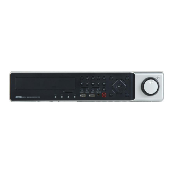
Product Description 1. Front Panel ① CD/DVD-RW : CD/DVD-RW Device for Archiving. ② Channel Selection Button : Select Channel (1 ~ 16) or Input Password Digits. ③ LED Indicator: Indicate Present System Status Information. ( PWR: System Power On/Off, REC: Record On/Off, ALARM: Alarm Sensor Status, NET: Network Client Connection Status, ) ④... - Page 11 Product Description 2. Rear Panel A. Video Inputs : Connect up to 16 BNC camera inputs. B. Main Monitor Out : BNC Main Monitor Output to A/V Monitor. Spot Monitor Out : BNC Spot Monitor Output to A/V Monitor. C. NTSC / PAL : Select NTSC or PAL Video Format. D.
-
Page 12: System Configuration - Remote Controller
SYSTEM CONFIGURATION – Remote Controller 3. Handheld IR Remote Controller POWER SETUP : Go to Main Setup Menu ON/OFF Channel Selection Buttons (also used for Password Digit Entry) ID Button Select DVR Unit ID ENTER : Confirm / Select / Next Screen RETURN Cancel / Deselect Navigation Buttons... - Page 13 & & • Connect up to 16 CAMERA INPUTS as necessary. • Connect one or more monitors to the DVR using the COMPOSITE or DVI (VGA). • Connect power to the DVR, using the provided DC 12V Power Adapter. The DVR will check for proper power connection and emits two beeps if system power test is OK. •...
-
Page 14: Live Display
MENU CONTROL All menus can be controlled from this „Status Bar‟ with either the USB mouse or Front Panel buttons. SCREEN DIVISION Select the „DISPLAY‟ button and the screen division menu will appear. Select the screen type (1, 4, 6, 8, 9, 16-channel or sequence). SEQUENCE MODE (User can select a sequence as one of the options within the screen division menu.) Press the „SEQ‟... -
Page 15: Digital Zoom
1) CAM: Select the Channel of the PTZ device which you are controlling. 2) Preset: Select the number of the preset you are working with (1 ~ 254). 3) Set: Sets the current PTZ position as the selected Preset number. 4) Goto: Tells the PTZ device to move to the position of the selected Preset. -
Page 16: Log Search
LOG SEARCH User can see a live event log window, which shows each new event as it occurs. Click on an event within the live event log window to begin playback from the selected event. (This will only happen when the „PREVIEW‟ option is selected from the live event log window.) PANIC RECORDING - This function button is used to toggle the Panic Recording mode On/Off. -
Page 17: Quick Menu
QUICK MENU You may access the „Quick Menu‟ by right-clicking on any channel which you would like to control. 1. Freeze On/Off: User can freeze the live display of any channel. While the other channels will continue to show live view video, the frozen channel display is stopped. Click once more to return to live view video. 2. -
Page 18: System Setup
SYSTEM SETUP Click the „MENU‟ button and choose the „SYSTEM SETUP‟ menu. - To navigate around any items in the setup menu, use the CURSOR KEYS and the „ENTER‟ and „RETURN‟ buttons. - In general, the „ENTER‟ button is used to select a particular field to edit, and then is pressed again to confirm changes. - The „RETURN‟... -
Page 19: Camera : Color Setup
SYSTEM SETUP CAMERA From the „System Setup‟ menu, click on the „CAMERA‟ submenu. CAMERA : CAMERA SETUP Left-click on the CAMERA SETUP menu. Double-click on the „TITLE‟ field to change the camera name. Click the „COVERT‟ fields for the desired channel. Then, use the button to modify each value. -
Page 20: Camera : Ptz Setup
SYSTEM SETUP Modify each value using the button. The selected channel is displayed in full screen mode. BRIGHTNESS, CONTRAST, TINT and COLOR can be changed as necessary. To modify a different channel, highlight the CAMERA field, and choose the desired channel. Press RETURN when all changes are completed. - Page 21 SYSTEM SETUP Advanced PTZ properties can be adjusted for each channel using the „DETAIL‟ button. Some settings, such as Auto Focus, may not be compatible with all PTZ devices. If this is the case, changing this value will have no effect on PTZ control. Click the „TOUR‟...
-
Page 22: Camera : Motion Sensor
SYSTEM SETUP CAMERA : MOTION SENSOR Click on the MOTION SENSOR menu. Click on a SENSITIVITY value for the desired channel. Then use the button to increase or decrease the sensitivity. SENSITIVITY : Determines the degree of motion required before recording is activated. (1: Least Sensitive to Motion - 10: Most Sensitive to Motion) Click the button to edit the motion detection area. -
Page 23: Display - Osd
SYSTEM SETUP DISPLAY From the „System Setup‟ menu, click on the „DISPLAY‟ submenu. DISPLAY - OSD Click on the „OSD‟ submenu and then click on any field. Then, click on the button to modify the value. STATUS BAR : Toggles the status bar at the bottom of screen in Live View mode ON / OFF. CAMERA TITLE : Determines whether the camera title is displayed for each channel. -
Page 24: Display - Monitor
SYSTEM SETUP DISPLAY - MONITOR Click the MONITOR menu, then click on any field. Use the button to modify the value. SEQUENCE DWELL : The amount of time that each screen is displayed in a sequence. SPOT-OUT DWELL : The amount of time that each screen is displayed on each of the spot monitor outputs. DE-INTERLACE MODE : When recording any channels in D1 resolution (704 x 480), this may be set to ON, to prevent interlaced motion distortion during playback. -
Page 25: Display - Sequence
SYSTEM SETUP DISPLAY - SEQUENCE Click the „SEQUENCE‟ menu. - When the „SEQ‟ button is pressed, the default sequence will cycle through all 16 channels, one by one, in full screen. - Sequence setup allows the user to define a custom sequence pattern, using either full screen or mixed multi-screen views, which can be comprised of any number of channels in any order. - Page 26 SYSTEM SETUP Click „ADD‟. The “Sequence Setup” submenu appears. - Determine the Screen Division mode under the “VIEW TYPE” section. - Assign the desired channel under the “CONFIGURE” section. - When all sequence settings have been entered correctly, click „CONFIRM‟. - To add an additional mode, click „ADD‟...
-
Page 27: Display - Spot Out
SYSTEM SETUP DISPLAY – SPOT OUT Click on the „SPOT-OUT‟ menu. Each DVR has up to 1 SPOT MONITOR OUTPUTS. The spot monitor displays a full screen sequence of particular channels, depending on the settings within this menu. The operator can decide which channels are to be displayed in the sequence. By default, The Spot Monitor output is set to run a sequence of all 16 channels. -
Page 28: Sound - Buzzer
SYSTEM SETUP SOUND From the „System Setup‟ menu, click on the „SOUND‟ menu. SOUND - BUZZER Click on the BUZZER menu, and click on any field. Use the button to modify each value. FRONT PANEL KEYPRESS: When enabled, each front panel button keypress is confirmed by a system beep. -
Page 29: System - Date / Time
SYSTEM SETUP SYSTEM From the „System Setup‟ menu, click the SYSTEM menu. SYSTEM - DATE / TIME Click the DATE / TIME menu, and click on any field. Use the button to modify any value. DATE TIME : Allows the operator to set or modify the current system date & time. DATE FORMAT : Determines the format in which the date is displayed. -
Page 30: System-System Management
SYSTEM SETUP SYSTEM-SYSTEM MANAGEMENT Click on the „SYSTEM MANAGEMENT‟ menu. F/W version: Shows the current firmware version of the DVR. H/W version: Shows the hardware version of the DVR. VIDEO SIGNAL TYPE: The DVR automatically switches between PAL and NTSC depending on the video format of the Channel 1 input signal at the time of power on. -
Page 31: System - Control Device
SYSTEM SETUP F/W UPDATE : Firmware updates may be released periodically to enhance system performance and add extra features. The user can upgrade the DVR firmware locally, using a USB memory stick. Select the Device where the Firmware Update files are located. After selecting the F/W version from F/W list, press „UPGRADE‟. -
Page 32: User - User Management
SYSTEM SETUP USER From the „System Setup‟ menu, click on the „USER‟ menu. USER - USER MANAGEMENT By default, the DVR is configured with a user ID of „ADMIN‟, belonging to the ADMIN group, with a password of „1234‟. Within this menu, you have the ability to add new users, or modify the details for existing users. To modify user details, click or highlight the user with the green cursor square, and press „ENTER‟. -
Page 33: User - User Authority
SYSTEM SETUP USER - USER AUTHORITY User can configure the specific authority and permissions for the MANAGER and USER groups. To confirm changes, click the „APPLY‟ button after selecting each of the desired items. NOTE: Any user can be deleted except the default „ADMIN‟ user account. USER - LOG OUT AUTO LOGOUT: Determines whether a logged-in user is automatically logged-out of the menu. -
Page 34: Network- Ip Setup
SYSTEM SETUP NETWORK From the „System Setup‟ menu, click on the „NETWORK‟ menu. NETWORK- IP SETUP Click on the „IP SETUP‟ menu. DHCP : When enabled, the DVR will obtain an IP address automatically from a router or DHCP server, upon reboot. WEB SERVICE : When enabled, allows remote connections using Internet Explorer or other compatible web browsers. -
Page 35: Network-Ddns
SYSTEM SETUP NETWORK-DDNS DDNS : When enabled, the DVR can be accessed through a Dynamic DNS server. (This is commonly used if a particular broadband connection does not have a Static IP address.) CAUTION: To use the DDNS function, the user must configure port forwarding. a. -
Page 36: Event / Sensor - Hdd Event
SYSTEM SETUP EVENT / SENSOR From the „System Setup‟ menu, click on the „EVENT / SENSOR‟ menu. EVENT / SENSOR - HDD EVENT Click on the „HDD EVENT‟ menu, and choose any field. . Use the button to modify the value. The DVR will continually monitor the health of the hard drives in the system and detect problems that may be developing. -
Page 37: Event / Sensor - Alarm Output
SYSTEM SETUP EVENT / SENSOR - ALARM OUTPUT Click on the ALARM OUTPUT menu, and click on a field. Use the button to modify the value. Behavior settings ALARM OUT : Choose which alarm output to configure. OPERATION : The selected alarm output can be enabled or disabled. MODE : Can be either set as „TRANSPARENT‟... -
Page 38: Event / Sensor - Buzzer Out
SYSTEM SETUP EVENT / SENSOR - BUZZER OUT Click on the BUZZER OUTPUT menu, and click on a field. Use the button to modify the value. This menu will determine the behavior and actions that will trigger the internal buzzer. Behavior settings OPERATION : The internal buzzer can be enabled or disabled. -
Page 39: Event / Sensor - E-Mail Notification
SYSTEM SETUP EVENT / SENSOR - E-MAIL NOTIFICATION Click on the EMAIL NOTIFICATION menu, and click on a field. Use the button to modify the value. This menu will determine the behavior and actions that will send an e-mail notification to a remote user. Behavior settings NOTIFICATION : E-mail notification can be enabled or disabled. -
Page 40: Disk Management
SYSTEM SETUP DISK MANAGEMENT Click on the DISK MANAGEMENT menu. To manage the internal hard drives, from the „System Setup‟ menu, highlight „DISK MANAGE‟ and press ENTER. RECORD TIME LIMIT: In certain circumstances, it may be necessary to limit the amount of footage stored. on the DVR (to comply with data protection laws, for example). -
Page 41: Record Setup
RECORD SETUP From the Main Menu, click on the „RECORD‟ menu. To configure the recording behavior of the DVR, highlight „RECORD MENU‟ and press „ENTER‟. RECORDING OPERATIONS Click on the „RECORDING OPERATIONS‟ menu. Click on any field, and use the button to modify the value. - Page 42 RECORD SETUP CONTINUOUS / MOTION RECORDING SETUP Click on the „CONTINUOUS / MOTION RECORDING‟ menu. This menu allows the operator to configure continuous and motion-activated recording, based on a schedule. There are 2 sections to this menu: SIZE / IPS / QUALITY:: Recording settings for each channel can be defined across a 24-hour period, in blocks (for example between 09:00 and 18:00) or by each individual hour.
- Page 43 RECORD SETUP SIZE / IPS / QUALITY (continued) Click on the TIMELINE to select a block of time. Press „ENTER‟ to display the green cursor. The green cursor square shown represents one hour. (In this case between 00:00 and 01:00). The table below the time bar shows the recording settings for this time period.
- Page 44 RECORD SETUP SIZE / IPS / QUALITY (continued) Click on the SIZE, IPS, QUALITY fields. Use the button to modify the value. Press ENTER. Recording settings for the selected time period are displayed. SIZE : Recording resolutions of CIF (352x240), 2CIF (704x240) or D1 (704x480) can be selected for each channel. FPS : Image rates between 1 and 30ips can be set for each channel.
- Page 45 RECORD SETUP SCHEDULE Click on the „SCHEDULE‟ menu. To change „SCHEDULE‟ settings, highlight „CONTINUOUS / MOTION RECORDING‟ and press „ENTER‟. Use the CURSOR KEYS to highlight „SCHEDULE‟ and press „ENTER‟. The schedule box is highlighted in green. Press „ENTER‟ to display the green cursor square. Example: To set all channels to motion detection recording only between 18:00 and 00:00.
-
Page 46: Alarm Recording
RECORD SETUP ALARM RECORDING Click on the „ALARM RECORDING‟ submenu. The layout of this menu is very similar to the „CONTINUOUS / MOTION RECORDING‟ menu. This menu screen allows the user to configure alarm-activated recording. There are 2 sections to this menu: SIZE / IPS / QUALITY:: Recording settings for each channel can be defined across a 24-hour period, in blocks SCHEDULE: This section determines at what times the DVR will record and whether it is set to continuous or motion. -
Page 47: Search - Search By Time
SEARCH To search for a particular section of recorded footage, click or press the „SEARCH‟ button. To protect unauthorized viewing of footage, only ADMIN and MANAGER user groups can playback footage (by default). To login as ADMIN, enter the default password of „1234‟ and press „ENTER‟. SEARCH –... - Page 48 SEARCH Click and drag the time bar across the timeline. Press ENTER to select the calendar and use the CURSOR KEYS to move the purple square to the desired day. As different days are selected, the timeline display also changes to show the timeline of recorded footage for that day. Press ENTER to choose the date and move to the timeline.
-
Page 49: Search Mode : Multi-Playback
SEARCH SEARCH MODE : PANO PANO (Panoramic or Time-of-Day Search) : Each display pane shows 3 hour of data. CH1 : 0~3 o‟clock CH2 : 3~6 o‟clock … CH8: 21~24 o‟clock User can select different channels and play back using variable play speeds - up to 64x. SEARCH MODE : Multi-Playback The default playback mode is 16-channel view. - Page 50 SEARCH During playback, user can put a bookmark on the recorded data that needs to be archived later. Click the button at the time the archive is to be started. Then playback will halt and menu below will appear. After inputting the “TAG” name, press START. Then the system will return to playback mode. Click the button again at the end point of the archive.
-
Page 51: Search - Search By Event
SEARCH To exit playback mode and return to the search screen in order to choose another time and date, press „RETURN‟. To exit the search screen and return to Live View mode, repeatedly press the „RETURN‟ button. SEARCH – SEARCH BY EVENT The DVR event log stores events such as motion and alarm activated recording, video loss etc. - Page 52 SEARCH Click the „SEARCH‟ button to search for events. Highlight „SEARCH‟ and press „ENTER‟ to display the event log for the criteria selected. To playback footage for a particular event, select the event from the list using the CURSOR KEYS and press „ENTER‟. Playback resumes from the moment the selected event occurred and continues until stopped by the user.
- Page 53 ARCHIVING To archive recorded footage to a USB Memory Stick or a CD/DVD disc, press the ARCHIVE button. To protect unauthorized viewing and distribution of footage, only the ADMIN user level can archive footage (by default). To login as ADMIN, enter the default password of „1234‟ and press „ENTER‟. CREATE A NEW ARCHIVE Click on a field to configure each of the archive settings.
-
Page 54: Reserved Data Management
ARCHIVING RESERVED DATA MANAGEMENT AVI ARCHIVING LIST: User can see the list of data that has been reserved from the „Create New Archive‟ menu INFORMATION : The detailed information of each clip that has been reserved. DELETE : Delete the selected clip from the list of reserved data. BURN : Perform an archiving operation using the selected clip. -
Page 55: W E B C O N N E C T I O N S E T Up
PRELIMINARY BEFORE CONNECTING When configuring for a web or remote connection to the DVR, Ports 554 and 8080 should be forwarded within the router. Refer to the user‟s manual of your specific model of router for information on port forwarding configuration. WEB / REMOTE CLIENT - MINIMUM PC REQUIREMENTS P4 (3.0GHz or higher) 512MB (or higher) -
Page 56: Connection Setup
The default User ID and Password are „ADMIN‟ & ‟1234‟, respectively. User will need to install the ActiveX control, click Run Add-on. In case of not being able to install ActiveX, the user needs to enable ActiveX within the IE security menu. Select „Enable‟... -
Page 57: Live Mode
LIVE MODE Icons and corresponding functions within LIVE mode: - Select Live View Screen Division (1, 4, 8, 9, 16-channel modes) - Sequence Mode - Move to Next Camera - Full Screen - Select Live View Channel Manually. - Save the current live image. - Print the current live image. - Page 58 - Status : Shows active status indicators of all channels on the DVR. Alarm - indicator will be marked when system detects Alarm Input. Motion - indicator will be marked when system detects Motion. Video Loss - indicator will be marked when system detects Video Loss. Recording - Display current recording mode.
-
Page 59: Search By Time
1. Pattern – move a camera to a sequence of several preset camera positions in order. 2. Preset – set a position of the camera to be recalled later. 3. Swing – move a camera between two or more preset points. SEARCH BY TIME - Select a position on the timeline or set an exact time. -
Page 60: Search By Event
SEARCH BY EVENT 1. Event : Select the types of events to search for within the recorded data. 2. Period : Set the date/time range to search for events within the recorded data. 3. Search : Begin query, and list all events found within selected range and type. 4. -
Page 61: Remote Setup
REMOTE SETUP 1. CAMERA : User can configure all camera attributes, such as title, covert channel, PTZ, or motion. - Motion Area Setup for individually configuring motion areas and sensitivity. - Page 62 1. CAMERA (continued) 1) Select the „Motion‟ submenu. 2) Select a channel and the motion sensitivity level. 3) Click and drag the mouse across the image grid to select motion areas. 4) Click OK. 2. DISPLAY 1) OSD - Configure properties for the on-screen display (OSD) of the DVR. 2) Monitor - Set dwell time for sequence, spot monitor output, and pop-up functions.
- Page 63 3. System Configure Date and Time Formats, NTP Time Server, Time Zone and DST properties. 4. Recording User can configure all of the recording parameters and schedules. (This is similar to the procedure for configuring these properties on the DVR system.)
- Page 64 5. User Add new users, configure existing users, authority level and log out time. 6. Network User can check the DVR network information and adjust the network bandwidth throttle. All other IP settings are not allowed to be changed remotely. These settings can only be changed locally. For setting up e-mail notification, user can configure the SMTP server details remotely.
- Page 65 7. Sensor Configure all options for Alarm Input, Alarm Output, Buzzer Out, and E-Mail Notification. The menu structure is very similar to the local DVR system setup for Event / Sensor. INFORMATION - Displays the DVR Model and WEB Remote Software Version.
- Page 66 1. Open the archive data, and Run the file [bplayer.exe], which is included within the backup folder. 2. Click the [Open File] button and choose the backup file you wish to open and verify.
- Page 67 3. After selecting the file, you will be asked to confirm whether or not you would like to check the watermark. 4. Click the [Yes] button to verify the embedded watermark. 5. If the archived AVI file has been modified, a [Verification Failed] message will appear.
-
Page 68: S M A R T P H O N E C O N N E C T I On
• iPhone 1. Select the Safari browser. 2. Enter the IP address or URL to connect. Click the [GO] button. 3. Enter the User ID and Password. (Default: ADMIN / 1234) - Page 69 • BlackBerry 1. Select the Web browser. 2. Enter the IP address or URL to connect, and press the Enter button. 3. Enter the User ID and Password. (Default: ADMIN / 1234)
- Page 72 Videor E. Hartig GmbH Exclusive distribution through specialized trade channels only. VIDEOR E. Hartig GmbH V. 1.0 Carl-Zeiss-Str. 8 · 63322 Rö dermark, Germany Technical changes reserved. Tel. +49 (0) 6074 / 888-0 · Fax +49 (0) 6074 / 888-100 ⓒ...
Need help?
Do you have a question about the BLR-3004 and is the answer not in the manual?
Questions and answers