
Related Manuals for Exerpeutic Elliptical 1302


Summary of Contents for Exerpeutic Elliptical 1302
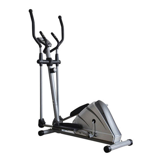
- Page 1 Elliptical OWNER’S Item #1302 MANUAL www.ActiveForever.com | Sales@ActiveForever.com p: 1-800-377-8033 | f: 602-296-0297...
-
Page 2: Table Of Contents
TABLE OF CONTENTS SERVICE ------------------------------------------------------------------------- 2 IMPORTANT LABELS -------------------------------------------------------- 3 PRODUCT SAFETY ----------------------------------------------------------- 4 PART DRAWING --------------------------------------------------------------- 5 PART LIST ----------------------------------------------------------------------- 6 INCLUDED HARDWARE ---------------------------------------------------- 8 TOOLS ---------------------------------------------------------------------------- 9 ASSEMBLY ---------------------------------------------------------------------- 10 COMPUTER --------------------------------------------------------------------- 17 ADJUSTMENTS ---------------------------------------------------------------- 18 TROUBLE SHOOTING & MAINTENANCE ----------------------------- 19 WARM UP ----------------------------------------------------------------------- 20 WARRANTY -------------------------------------------------------------------- 21... -
Page 3: Service
SERVICE IMPORTANT: FOR NORTH AMERICA ONLY To request product service and order replacement parts, please call our customer service department at: 1-866-924-1688 Please have the following information ready when requesting for service: Your name Phone number Model number Serial number Part number Proof of Purchase *Before returning this product to the store please contact... -
Page 4: Important Labels
IMPORTANT LABELS... -
Page 5: Product Safety
PRODUCT SAFETY Basic precautions should always be followed, including the following safety instructions when using this equipment: Read all instructions before using this equipment. 1. Read all the instructions in this manual and do warm up exercises before using this equipment. Before exercise, in order to avoid injuring your muscles, warm-up exercise for every muscle group is highly recommended. -
Page 6: Part Drawing
PART DRAWING... -
Page 7: Part List
PART LIST Description Qty No. Description 001 Main Frame 80x40x2 1 025 Washer Ø6 002L Left Foot Bar 40x25x1.5 1 026 Bolt M6x40 002R Right Foot Bar 40x25x1.5 1 027 Tension Cable L=1800 003L Left Handrail Arm Ø32x1.5 1 028 Cap S13 003R Right Handrail Arm Ø32x1.5 1 029 Screw ST4.2x25 004L Left Handrail Ø32x1.5... - Page 8 PART LIST Description Qty No. Description 051 Tension Control Knob 1 073 Washer Ø34.5xØ23x2.5 052 Screw ST4.2x20 2 074 Hexagon Nut 7/8” 053 Computer (JVT29121) 1 075 Belt Pulley with Crank 6.5”/Ø260 054 Rear Decorative Cover Ø60 1 076 Big Washer Ø6 055 Hand Pulse Sensor with Wire 2 077 M10x1 Nut for Flywheel L=750...
-
Page 9: Included Hardware
INCLUDED HARDWARE (13R) Bolt for right U Shape (13L) Bolt for left U Shape Bracket 1/2” 1 PC Bracket 1/2” 1 PC (14R) Right Nylon Nut 1/2” 1 PC (14L) Left Nylon Nut 1/2” 1 PC (15) Wave Washer (15) Wave Washer Ø28xØ17x0.3 1 PC Ø28xØ17x0.3... -
Page 10: Tools
TOOLS Allen Wrench 8mm Allen Wrench 6mm 1 PC 1 PC Multi Hex Multi Hex Tool with Phillips Screwdriver Tool S8, S13, S14, S15 1 PC 1 PC... -
Page 11: Assembly
ASSEMBLY (9) Bolt M8x70, 4 PCS (11) Big Curve Washer, 4 PCS (12) Cap Nut M8, 4 PCS Remove Bolt (38), Washers (11) and (41) from Main Frame (1). - Page 12 ASSEMBLY Insert Tension Cable (27) into Front Post (5) and pull it out though the square hole. Connect Sensor Wires (64) and (65). Install Bolt (38), Washers (11) and (41).
- Page 13 ASSEMBLY Connect Tension Control Knob cable (51) to the Tension Cable (27). Install the Knob using Bolt (62) and Washer (61) removed from the Knob. Remove Bolts (40), Spring Washers (41), Big Washers (46), and Washers (42) from the left and right horizontal axes of the Front Post (5).
- Page 14 ASSEMBLY (13L/R) Bolt for left/right U Shape Bracket 2 PCS (14L/R) Left/Right Nylon Nut 2 PCS (15) Wave Washer 2 PCS (17) Spring Washer 2 PCS Insert a 1/2” Bolt for left U Shape Bracket (13L) and put the Wave Washer (15) through the left U Shape Bracket (20).
- Page 15 ASSEMBLY Attach the Foot Bar Covers-A/B (30L, 30R) (29) onto the Left Foot Bar (2L) with one Screw (29) and two Phillips Self Tapping Screws (60). (Repeat step for right side). (60) (29) Screw, 2 PCS (60) Phillips Self Tapping Screw, 4 PCS (24) Nylon Nut M6, 6 PCS (25) Washer Ø6, 6 PCS...
- Page 16 ASSEMBLY (44) Bolt M6x35, 4 PCS (45) Curve Washer Ø6, 4 PCS (24) Nylon Nut M6, 4 PCS Attach the Left/Right Handrails (4L, 4R) onto the Left/Right Handrail Arms (3L, 3R) with Bolts (44), Curve Washers (45), and four Nuts (24). (29) Screw, 2 PCS (87) Screw, 8 PCS Attach the Front and Rear...
- Page 17 ASSEMBLY Remove Bolts (88) from the back of the Computer (53). Remove Bolts (38) and Curve Washers (93) from the Front Post (5). Insert the Hand Pulse Sensor Wires (55) from the Handlebar (6) into the hole on the Front Post (5) and then pull them out from the top end of the Front Post (5).
-
Page 18: Computer
COMPUTER Button functions: MODE: Display play function selection. Press 3 seconds to reset values to 0, except odometer. SET: To set goal values of TIME, DISTANCE, CALORIES, or PULSE. RESET: To clear goal values. Press 3 seconds to reset values to 0, except odometer. Display functions: SCAN automatically scans through each display mode at 6-second intervals. -
Page 19: Adjustments
ADJUSTMENTS Adjusting the Tension Control Knob To increase the load, turn the tension control knob in a clockwise direction. To decrease the load, turn the tension control knob in a counterclockwise direction. Tension Control Knob Adjusting the Rear Stabilizer End Cap Turn the rear stabilizer end cap on the rear stabilizer as needed to level the elliptical trainer. -
Page 20: Trouble Shooting & Maintenance
TROUBLE SHOOTING & MAINTENCE TROUBLE SHOOTING Computer not working correctly Check to make sure the computer cable is connected securely. Make sure the batteries are installed correctly. Make sure the batteries are not dead. No resistance Turn the tension knob to lowest tension, pull the friction belt through the buckle to tighten. -
Page 21: Warm Up
WARM UP Quadriceps Stretch With one hand against a wall for balance, reach behind you and pull your right foot up. Bring your heel as close to your buttocks as possible. Hold for 15 counts and repeat with left foot up. Inner Thigh Stretch Sit with the soles of your feet together with your knees pointing outward. -
Page 22: Warranty
WARRANTY Paradigm Health & Wellness, Inc. warrants to the original purchaser that this product is free from defects in material and workmanship when used for the purpose intended, under the conditions that it has been installed and operated in according to Paradigm’s Owner’s Manual.
Need help?
Do you have a question about the Elliptical 1302 and is the answer not in the manual?
Questions and answers