Table of Contents

Related Manuals for Exerpeutic 1318


Summary of Contents for Exerpeutic 1318
- Page 1 Elliptical IMPORTANT: Read all instructions carefully before using this product. Retain this owner’s manual for future reference. The specifications of this product may vary from this photo, subject to change without notice. OWNER’S MANUAL Item #1318...
-
Page 2: Table Of Contents
TABLE OF CONTENTS SERVICE ------------------------------------------------------------------------ 2 LABEL PLACEMENT --------------------------------------------------------- 3 PRODUCT SAFETY ---------------------------------------------------------- 4 OVERVIEW DRAWING ------------------------------------------------------ 5 PARTS LIST --------------------------------------------------------------------- 6 HARDWARE LIST & TOOLS ----------------------------------------------- 9 ASSEMBLY ---------------------------------------------------------------------- 10 COMPUTER --------------------------------------------------------------------- 25 ADJUSTMENT ----------------------------------------------------------------- 33 TROUBLE SHOOTING & MAINTENANCE ----------------------------- 34 WARM UP ---------------------------------------------------------------------- 35 WARRANTY -------------------------------------------------------------------- 36 FAX FORM ---------------------------------------------------------------------- 37... -
Page 3: Service
SERVICE IMPORTANT: FOR NORTH AMERICA ONLY To request product service and order replacement parts, please call our customer service department at: 1-866-924-1688 Monday through Friday, 8:00 AM-5:00 PM Pacific Standard Time, service@paradigmhw.com or email us at: Please visit our website at www.paradigmhw.com. Please have the following information ready when requesting for service: Your name Phone number... -
Page 4: Label Placement
LABEL PLACEMENT... -
Page 5: Product Safety
PRODUCT SAFETY Basic precautions should always be followed, including the following Important safety instructions when using this equipment. Read all instructions before using this equipment. Read all the instructions in this manual and do warm up exercises before using this product. Before exercise, in order to avoid injuring your muscles, warm-up exercise for every muscle group is highly recommended. -
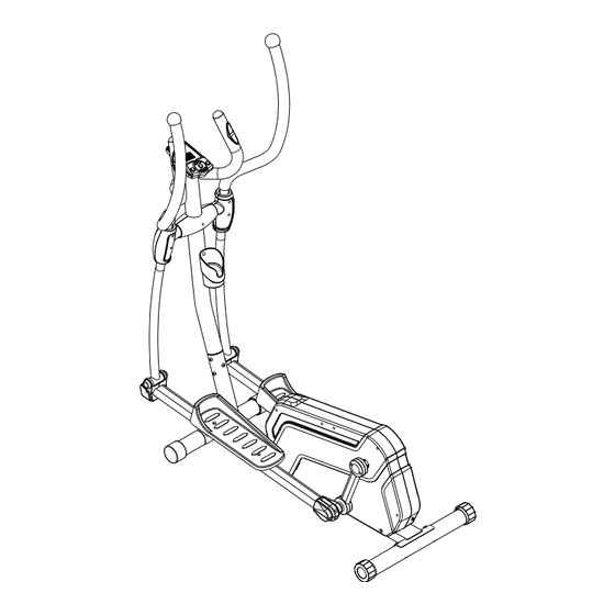
Page 6: Overview Drawing
OVERVIEW DRAWING... -
Page 7: Parts List
PARTS LIST Description Qty No. Description 001 Main Frame 1 021R Right Cover 002 Front Stabilizer Ø60x1.5tx510mm 1 022L Left Foot Pedal 003 Rear Stabilizer Ø60x1.5tx590mm 1 022R Right Foot Pedal 004 Front Post Ø60x2.0tx925mm 1 023A Lower Crank Cover A (Black) 005 Handlebar Ø32 1 023B Lower Crank Cover B (Black) 006L Upper Left Handrail Ø32... - Page 8 PARTS LIST Description Qty No. Description 044 Nylon Locknut M10 4 070 Wave Washer Ø16.2xØ25x0.5t 045 Nylon Locknut M6 4 071 Washer Ø8xØ25x2.0T Hexagon Socket Head Bolt 046 Washer Ø6xØ14x1.0t 6 072 M8x54mm Hexagon Socket Head Bolt 047 Tension Bracket & Eyebolt Set I 2 073 M8x50mm 048 Washer Ø10xØ20x3.0T...
- Page 9 PARTS LIST Description Qty No. Description 095 Belt 340J6 1 102 Computer 096 Idle Wheel 10x36x22 2 103 Bolt for Computer 097A U Shape Bracket Cover A 1 104 Spring 2.6x18 097B U Shape Bracket Cover B 1 105 Idler Arm Hexagon Socket Head Bolt 098 Motor 1 106...
-
Page 10: Hardware List & Tools
HARDWARE LIST & TOOLS (#34) Carriage Bolt (#35) Cap Nut M8 (#36) Washer (#18) Washer 4 PCS 4 PCS 4 PCS 2 PCS (#39) Hexagon Socket (#40) Nylon Locknut (#43) Carriage Bolt (#45) Nylon Locknut Head Bolt 4 PCS 4 PCS 4 PCS 4 PCS (#46) Washer... -
Page 11: Assembly
ASSEMBLY Tool: Multi Hex Tool with Phillips Screwdriver Front Stabilizer Installation. Lift up the main frame (1) towards the front, and then align the Front Stabilizer (2) onto the front curve of the Main Frame (1). Attach two Carriage Bolts (34) and on the other ends of bolts with two Washers (36) and two Cap Nuts (35). - Page 12 ASSEMBLY Tool: Multi Hex Tool with Phillips Screwdriver Rear Stabilizer Installation. Lift up the Main Frame (1) towards the end, and then align the Rear Stabilizer (3) onto the rear curve of the Main Frame (1). Attach Two Carriage Bolts (34) and on the other ends of bolts with two Washers (36) and two Cap Nuts (35).
- Page 13 ASSEMBLY Tool: Allen Wrench Assemble Front Post. Use the Allen Wrench to remove six Hexagon Socket Head Bolts (32), six Spring Washers (80), and six Curve Washers (38) from the Main Frame (1). Connect the Computer Wire (12) from the Front Post (4) with the Extension Sensor Wire (15) from the Main Frame (1).
- Page 14 ASSEMBLY Tool: Allen Wrench Assemble Handlebar. A. Use Allen Wrench to remove two Hexagon Socket Head Bolts (32) and two Curve Washers (38) from the Front Post (4). Take off the Wire Plug (89) from the right hand side of the Front Post (4). B.
- Page 15 ASSEMBLY Tool: Allen Wrench Multi Hex Tool with Phillips Screwdriver Assemble Upper Handrails and Handrail Arms: “R” for right side and “L” for left side. A. Insert the Upper Left Handrail (6L) into Left Handrail Arm (7L), tighten with two Hexagon Socket Head Bolts (39) and two Nylon Locknuts (40) by Allen Wrench and Multi Hex Tool with Phillips Screwdriver.
- Page 16 ASSEMBLY Tool: Allen Wrench Assemble Upper Handrails and Front Post: “R” for right side and “L” for left side. Insert Plastic Bushings (50) on both sides of the central axis on the Front Post (4). Attach Washers (51) behind them. Insert the Upper Left/Right Handrails (6L, 6R) onto both sides of the central axis on the Front Post (4).
- Page 17 ASSEMBLY Tool: Multi Hex Tool with Phillips Screwdriver Assemble Foot Pedals: “R” for right side and “L” for left side. A. Place the Left Foot Pedal (22L) on top of the Left Foot Bar (9L), align to the bolt hole with two Carriage Bolts (43) two Washes (46) and two Nylon Locknuts (45) by using Multi Hex Tool with Phillips Screwdriver.
- Page 18 ASSEMBLY Tool: Allen Wrench Assemble Foot Bars: “R” for right side and “L” for left side. A. Insert the U shape bracket (8) at the back of the Left Foot Bar (9L) into the left Crank (10). Then attach one Wave Washer (70), following with another Washer (71), at the end lock it with one Hexagon Socket Head Bolt (53).
- Page 19 ASSEMBLY Tool: Multi Hex Tool with Phillips Screwdriver Allen Wrench Assemble Handrail Arms: “R” is for right side and “L” is for left side. A. Remove two Hexagon Socket Head Bolts (41), two Washers (42) and two Nylon Locknuts (44) from the Left/Right Foot Bars (9L, 9R) by using the Allen Wrench. B.
- Page 20 ASSEMBLY Tool: Multi Hex Tool with Phillips Screwdriver 10. Assemble Front and Rear Decorate Covers for Front Post and Handrail Arm Covers A/B. A. Remove two Bolts (69) from the Front and Rear Decorate Covers (13A, 13B) by using the Multi Hex Tool with Phillips Screwdriver. B.
- Page 21 ASSEMBLY Tool: Multi Hex Tool with Phillips Screwdriver 11. Assemble U Shape Bracket Covers. Place the U Shape Bracket Covers A/B (97A, 97B) around the U Shape Brackets (8). Make sure the side with holes is facing the Crank (10). Tight them with four Round Head Self Tapping Screws (59) by using the Multi Hex Tool with Phillips Screwdriver until firm and secure.
- Page 22 ASSEMBLY Tool: Multi Hex Tool with Phillips Screwdriver 12. Assemble Foot Bar Covers A/B. Place the Foot Bar Covers-A/B (75A, 75B) around the Left/Right Foot Bars (9L, 9R). Make sure the side with holes on the Foot Bar Covers-A/B (75A, 75B) is facing the Left/Right Foot Bars (9L, 9R).
- Page 23 ASSEMBLY Tool: Multi Hex Tool with Phillips Screwdriver 13. Computer Installation. Remove four Bolts for Computer (103) from the Computer (102) by using the Multi Hex Tool with Phillips Screwdriver. Connect the Computer Wire (12) and Hand Pulse Sensor Wires (17) from the top end of Front Post (4) with the wires that come from the Computer (102).
- Page 24 ASSEMBLY Tool: Multi Hex Tool with Phillips Screwdriver 14. Bottle Holder Installation. Remove two Bolts (33) on the Front Post (4). Attach the Bottle Holder (101) onto the Front Post (4), then tighten them with two Bolts (33) that were removed by using the Multi Hex Tool with Phillips Screwdriver until firm and secure.
- Page 25 ASSEMBLY 15. Adaptor Installation. Plug one end of the Adaptor (100) into the power jack of the Power Supply Cable (99) on the back of the Right Cover (21R). Before plugging in, make sure to check carefully the specifications on the Adaptor. Plug the other end of the Adaptor (100) into the electrical wall outlet.
-
Page 26: Computer
COMPUTER To quick start, press these buttons in order: 1. RESET -> 2.UPPER ARROW -> 3. START/STOP -> 4. ENTER I. Display: 1. The field is an individual LCD displaying: TIME, RPM\SPEED, DISTANCE, WATT\CALORIES, PULSE, USER. 2. Dot matrix display: ●... - Page 27 COMPUTER III. USER Operation instructions (U0~U4): Select USER 0, USER 1, USER2, USER 3, USER 4: The message reads “U0” until a selection is made. By pressing ▲ or ▼ button to choose from “U0 ~U4”. 1. Press ENTER button to accept “U0~U4”. By pressing the ▲ or ▼ button to adjust the SEX (FEMALE/MALE).
- Page 28 COMPUTER 2. If Press ENTER button to accept PROGRAM By pressing the ▲ or ▼ button to adjust the P1-P12 Press ENTER button to accept program. By pressing the ▲ or ▼ button to adjust the Profile . Press ENTER button to accept LEVEL. By pressing the ▲ or ▼ button to adjust the TIME value.
- Page 29 COMPUTER Press ENTER button to accept TIME. By pressing the ▲ or ▼ button to adjust the DISTANCE value. Press ENTER button to accept DISTANCE. By pressing the ▲ or ▼ button to adjust the CALORIES value. 6. If Press ENTER button to accept H.R.C. (55%, 75%, 90%, Tag) By pressing the ▲...
- Page 30 COMPUTER 2. ENTER button: To confirm set value and enter into the next set value. 3. ▲ and ▼ button: (1). Used to change SEX, AGE, HEIGHT, WEIGHT, TIME, DISTANCE, CALORIES, TARGET HRC and LEVEL; (2). Work level can be changed during a workout. 4.
- Page 31 COMPUTER VII. Pre-defined program profile: ● MANUAL ● PROGRAM ● FITNESS ● PERSONAL ● WATT ● H.R.C. ● RANDOM Program Profile for the P1~P12 Program ● P2 ● P1 ● P3...
- Page 32 COMPUTER ● P5 ● P6 ● P4 ● P8 ● P9 ● P7 ● P11 ● P10 ● P12 Program Profile for the H.R.C. (55%, 75%, 90%, Tag) Program ●HRC (75%) ●HRC (55%) ●HRC (90%) ●HRC (Tag)
- Page 33 Here is the Bluetooth set up example for IPOD. Download APP Application Turn on the IPOD, Go to Apple Store and “Search”. Search for “Exerpeutic pedal monitor”. Click Download. After download successfully, “Pedal Monitor” application will show on the interface.
-
Page 34: Adjustment
ADJUSTMENT Rear Stabilizer End Cap Adjusting the Rear Stabilizer End Cap Turn the rear stabilizer end cap on the rear stabilizer as needed to level the elliptical. -
Page 35: Trouble Shooting & Maintenance
TROUBLE SHOOTING & MAINTENANCE TROUBLE SHOOTING PROBLEM: The elliptical wobbles when in use. SOLUTION: Turn the rear stabilizer end cap on the rear stabilizer as needed to level the elliptical. PROBLEM: There is no display on the computer console. SOLUTION: Remove the computer console and verify the wires that come from the computer console are properly connected to the wires that come from the front post. -
Page 36: Warm Up
WARM UP Quadriceps Stretch With one hand against a wall for balance, reach behind you and pull your right foot up. Bring your heel as close to your buttocks as possible. Hold for 15 counts and repeat with left foot up. Inner Thigh Stretch Sit with the soles of your feet together with your knees pointing outward. -
Page 37: Warranty
WARRANTY Paradigm Health & Wellness, Inc. warrants to the original purchaser that this product is free from defects in material and workmanship when used for the purpose intended, under the conditions that it has been installed and operated in according to Paradigm Health & Wellness, Inc.’s Owner’s Manual. Paradigm Health &... -
Page 38: Fax Form
FAX FORM Paradigm Health & Wellness, Inc. PARTS REQUEST FAX FORM Please fax this form to (1-626-810-2166) OR YOU CAN EMAIL CUSTOMER SERVICE REQUESTS TO service@paradigmhw.com NAME: _______________________________________________________ ADDRESS: ____________________________________________________ CITY ______________ STATE ______________ ZIP ___________________ TELEPHONE: (Day) _____________________________________________ (Night) ____________________________________________ (Email Address) ____________________________________ SERIAL#: __________________________________________ MODEL#: __________________________________________...
Need help?
Do you have a question about the 1318 and is the answer not in the manual?
Questions and answers
What are the specs of the power adapter