Table of Contents

Related Manuals for Exerpeutic 1302.4


Summary of Contents for Exerpeutic 1302.4
- Page 1 Elliptical IMPORTANT: Read all instructions carefully before using this product. Retain this owner’s manual for future reference. The specifications of this product may vary from this photo, subject to change without notice. OWNER’S MANUAL 1302.4-031016...
-
Page 3: Table Of Contents
TABLE OF CONTENTS SERVICE ------------------------------------------------------------------------ 2 LABEL PLACEMENT --------------------------------------------------------- 3 PRODUCT SAFETY ---------------------------------------------------------- 4 OVERVIEW DRAWING ------------------------------------------------------ 5 PART LIST ----------------------------------------------------------------------- 6 HARDWARE PACK------------------------------------------------------------ 7 ASSEMBLY ---------------------------------------------------------------------- 8 COMPUTER -------------------------------------------------------------------- 16 ADJUSTMENTS --------------------------------------------------------------- 17 MOVING THE ELLIPTICAL ------------------------------------------------- 18 TROUBLE SHOOTING & MAINTENANCE ----------------------------- 19 WARRANTY -------------------------------------------------------------------- 20 PARTS REQUEST FORM --------------------------------------------------- 21... -
Page 4: Service
SERVICE IMPORTANT: FOR NORTH AMERICA ONLY For damaged or defective products, questions, replacement parts or any other needed service support, please contact our customer service department (8:00 AM - 5:00 PM Pacific Standard Time, Daily) by below methods: For Best Service Email: Service@paradigmhw.com * Website: www.paradigmhw.com... -
Page 5: Label Placement
LABEL PLACEMENT... -
Page 6: Product Safety
PRODUCT SAFETY Basic precautions should always be followed, including the following safety instructions when using this equipment: Read all the instructions before using this equipment. 1. Read all the instructions in this manual and do warm up exercises before using this equipment. -
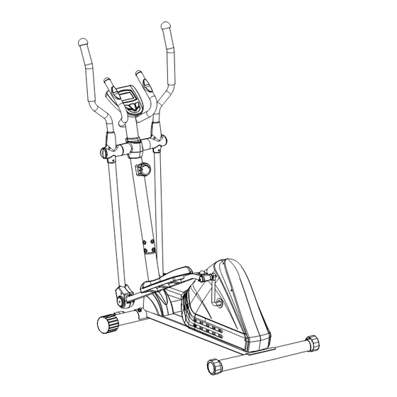
Page 7: Overview Drawing
OVERVIEW DRAWING... -
Page 8: Part List
PART LIST Description Qty No. Description 001 Main Frame 80x40x2 1 030R Foot Bar Cover-B 002L Left Foot Bar 40x25x1.5 1 033 Left Foot Pedal 395x150x65 002R Right Foot Bar 40x25x1.5 1 034 Right Foot Pedal 395x150x65 003L Left Handrail Arm Ø32x1.5 1 038 Hexagon Socket Head Bolt M8x15 003R Right Handrail Arm Ø32x1.5 1 040 Hexagon Socket Head Bolt M8x20... -
Page 9: Hardware Pack
HARDWARE PACK... -
Page 10: Assembly
ASSEMBLY Multi Hex Tool with Phillips Screwdriver S8, S13, S14, S15 1 PC 1. Front and Rear Stabilizers Installation: Step A: Align the Front Stabilizer (7) onto the front curve of the Main frame (1). Make sure the transport wheels are positioned toward the front and parallel to the floor. Install two Carriage Bolts (9) from the bottom, and on the other ends of the bolts attach two Big Curve Washers (11) and two Cap Nuts (12). - Page 11 ASSEMBLY 6mm Allen Wrench 1 PC Multi Hex Tool with Phillips Screwdriver S8, S13, S14, S15 1 PC MUST TIGHTEN IN SEQUENCE: A,B,C,D,E,F,G,H. 2. Front Post and Tension Control Knob Installation Remove the eight Hexagon Socket Head Bolts (38), eight Big Curve Washers (11), and eight Spring Washers (41) from the Main Frame (1) first.
- Page 12 ASSEMBLY 6mm Allen Wrench 1 PC 3. Handrail Arm Installation Remove the Pre-Installed Hexagon Socket Head Bolts (40), Spring Washers (41), Big Washers (46), and Washers (42) from the left and right horizontal posts on the Front Post (5). Slide a Plastic Bushing (48) down the horizontal shaft on the left side of Front Post (5), and then attach the Left Handrail Arm (3L) onto the left horizontal post on the Front Post (5).
- Page 13 ASSEMBLY 8mm Allen Wrench 1 PC Multi Hex Tool 1 PC 4. Foot Bar Installation Insert the Left Bracket Bolt (13L) along with a Wave Washer (15) through the U Shaped Bracket (20) located on the back of the Left Foot Bar (2L). Secure the Left Bracket Bolt (13L) to the Left side of the Crank (75) by turning the Bolt Counter-Clockwise.
- Page 14 ASSEMBLY Multi Hex Tool with Phillips Screwdriver S8, S13, S14, S15 1 PC 5. Pedal Installation Install the Left Foot Pedal (33) onto the Left Foot Bar (2L) using three Bolts (26), three Washers (25) and three Nylon Nuts (24). Tighten the Nylon Nuts (24) using the Multi Hex Tool with Phillips Screwdriver.
- Page 15 ASSEMBLY Multi Hex Tool with Phillips Screwdriver S8, S13, S14, S15 1 PC 7. Handrail Installation Attach the Left Handrail (4L) onto the Left Handrail Arm (3L) using two Carriage Bolts (44), two Curve Washers (45) and two Nylon Nuts (24). Tighten the Nylon Nuts (24) with the Multi Hex Tool with Phillips Screwdriver provided.
- Page 16 ASSEMBLY Multi Hex Tool with Phillips 6mm Allen Wrench Screwdriver 1 PC S8, S13, S14, S15 1 PC 8. Computer Installation Remove the two Bolts (88) from the back of the Console (53). Then remove the two Bolts (38) and two Curve Washers (93) from the Front Post (5). Insert the Hand Pulse Sensor Wires (55) from the Handlebar (6) into the hole on the forward facing side of the Front Post (5), and pull them up, and out of the top end of the Front Post (5).
- Page 17 ASSEMBLY Multi Hex Tool with Phillips Screwdriver S8, S13, S14, S15 1 PC 9. Cover Installation Attach the Front and Rear Covers (90, 54) onto the Front Post (5) using two Screws (29). Then, tighten using the Multi Hex Tool with Phillips Screwdriver. Attach the Left Handrail Arm Cover-A (49L) and Left Handrail Arm Cover-B (50L) onto the Left Handrail Arm (3L) with four Screws (94) and tighten using the Multi Hex Tool with Phillips Screwdriver.
-
Page 18: Computer
COMPUTER Button functions: MODE: Press to change the current statistics being displayed. Hold for 3 seconds to reset all the workout statistics to 0, except odometer. SET: Use to set a goal value for TIME, DISTANCE, CALORIES, or PULSE. RESET: Resets the current exercise values, as well as goal values. Hold for 3 seconds to reset all the workout statistics to 0, except odometer. -
Page 19: Adjustments
ADJUSTMENTS Adjusting the Tension Control Knob To increase the resistance, turn the Tension Control Knob (51) in a CLOCKWISE direction. To decrease the resistance, turn the Tension Control Knob (51) in a COUNTER-CLOCKWISE direction. Adjusting the Rear Stabilizer End Cap Turn the Rear Stabilizer End Caps (10) on the Rear Stabilizer (8) as needed to level the Elliptical. -
Page 20: Moving The Elliptical
MOVING THE ELLIPTICAL Transporting the Elliptical Hold the Handlebar (6) and pull the machine until the wheels on the Front Stabilizer (7) make contact with the floor. Push or pull the unit to the desired location, then gently lower the Rear Stabilizer (8) to the ground. -
Page 21: Trouble Shooting & Maintenance
TROUBLE SHOOTING & MAINTENANCE TROUBLE SHOOTING Console is not operating correctly Check to make sure the console cable is securely connected. Make sure the batteries are installed correctly. Make sure the batteries still have a charge. No resistance Turn the Tension Control Knob (51) to the lowest setting, Remove the Tension Control Knob (51) from the Front Post (5) and make sure the Tension Cable (27) is still connected to the Tension Cable coming from the Tension Control Knob (51). -
Page 22: Warranty
WARRANTY MANUFACTURER’S LIMITED WARRANTY Paradigm Health & Wellness warrants to the original purchaser that this product is free from defects in material and workmanship when used for the purpose intended, under the conditions that it has been installed and operated in accordance with Paradigm’s Owner’s Manual. -
Page 23: Parts Request Form
PART REQUEST FORM Paradigm Health & Wellness, Inc. EMAIL THIS FORM WITH YOUR RECIEPT OF PURCHASE TO Service@paradigmhw.com * NAME: _______________________________________________________ ADDRESS: ____________________________________________________ CITY ______________ STATE ______________ ZIP ___________________ TELEPHONE: (Day) _____________________________________________ (Night) ____________________________________________ SERIAL#: ______________________________________________________ MODEL#: _____________________________________________________ PURCHASE DATE: _____________________________________________ PLACE OF PURCHASE: _________________________________________ PART # DESCRIPTION...
Need help?
Do you have a question about the 1302.4 and is the answer not in the manual?
Questions and answers