Table of Contents

Related Manuals for Exerpeutic 5000


Summary of Contents for Exerpeutic 5000
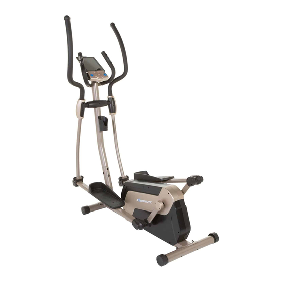
- Page 1 ELLIPTICAL IMPORTANT: Read all instructions carefully before using this product. Retain this owner’s manual for future reference. The specifications of this product may vary from this photo and, subject to change without notice. OWNER’S MANUAL 1318Y.2-082818...
- Page 2 PLEASE DO NOT RETURN THIS PRODUCT TO THE STORE. STOP. Contact customer service if you have any questions regarding assembly or proper operation of the machine. Email us at: Service@paradigmhw.com Or call us at: 1-844-641-7921 Hours: 8:00 am to 5:00 pm (PST) Monday thru Friday...
-
Page 3: Table Of Contents
TABLE OF CONTENTS SERVICE ------------------------------------------------------------------------------------ LABEL PLACEMENT --------------------------------------------------------------------- IMPORTANT SAFETY GUIDELINES ------------------------------------------------ OVERVIEW DRAWING ------------------------------------------------------------------ PARTS LIST -------------------------------------------------------------------------------- HARDWARE & TOOLS PACK -------------------------------------------------------- ASSEMBLY --------------------------------------------------------------------------------- CONSOLE---------------------------------------------------------------------------------- ADJUSTMENTS--------------------------------------------------------------------------- TROUBLESHOOTING & MAINTENANCE ----------------------------------------- WARRANTY ------------------------------------------------------------------------------- PARTS REQUEST FORM -------------------------------------------------------------... -
Page 4: Service
SERVICE IMPORTANT: FOR NORTH AMERICA ONLY For damaged or defective product, questions, replacement parts or any other service support, please contact our customer service department by the below methods: For The Best Service, please Email: service@paradigmhw.com Response Time: 1-2 Business Days Emailing us with the information above will be the best method to receive a response during peak business hours Website:... -
Page 5: Label Placement
LABEL PLACEMENT... -
Page 6: Important Safety Guidelines
IMPORTANT SAFETY GUIDELINES Read all guidelines before using this machine. When using this machine, basic precautions should always be followed, including the following: WARNING - To reduce the risk of injury to persons: Make sure your equipment is correctly assembled before you use it. Be sure all screws, nuts, and bolts are tightened prior to use. - Page 7 IMPORTANT SAFETY GUIDELINES Do not use this equipment if you have any of the following conditions or ailments: Pregnancy Extreme obesity Middle ear infection Hiatus hernia or Ventral hernia Glaucoma, retinal detachment or conjunctivitis Use of anticoagulants including Aspirin in high doses.
-
Page 8: Overview Drawing
OVERVIEW DRAWING... - Page 9 OVERVIEW DRAWING...
-
Page 10: Parts List
PARTS LIST Description Description Right Foot Bar Cover Ⅰ Main Frame Right Foot Bar Cover Ⅱ Front Post Handrail Arm Hex Bolt M12*80 Flat Washer φ24*φ12.5*2 Left Handrail Right Handrail Anti-Loose Hex Nut M12 Left Foot Bar Left Pedal Right Foot Bar Right Pedal Front Stabilizer Ф60*1.5*480 Carraige Bolt M6*45... - Page 11 PARTS LIST Description Description Self-Tapping Phillips Screw ST4.8*15 Eye Bolt M6*36 U-Bracket 31*30*δ1.0 Flange Nut M10*1.25*6 Crank Cover Ⅲ Hex Nut M6 Shroud Plug φ82*φ42*8 Axle Ring Φ12*1.0 Belt Pulley Shaft Φ12*94-M10*1 Left Protective Cover Right Protective Cover Bearing 6001 C-Ring Φ17*1.0 Belt Pulley Wave Washer Φ20*Φ24*0.3...
-
Page 12: Hardware & Tools Pack
HARDWARE & TOOLS PACK... -
Page 13: Assembly
ASSEMBLY Tool: 6 mm Allen Wrench Step 1 1a. Remove the Metal Tubes A & B from the Main Frame (1) by using 6mm Allen Wrench provided. 1b. Discard the Metal Tubes A & B and the associated hardware at that was removed. These parts are not needed for the assembly of the elliptical. - Page 14 ASSEMBLY Tool: Multi Hex Tool with Phillips Screwdriver STEP 2 2a. Installing the Front Stabilizer –Lift up the front of the Main Frame (1), and then align the holes of the Front Stabilizer (8) with the holes on the front curve of the Main Frame (1). Insert two Carriage Bolts (61) and attach two Big Curved Washers (22), two Spring Washers (21), and two Cap Nuts (62) to the threaded side of the two Carriage Bolts (61).
- Page 15 ASSEMBLY Tool: 6 mm Allen Wrench MUST TIGHTEN IN SEQUENCE: A,B,C,D,E,F,G,H. STEP 3 3a. Removing The Hardware From The Front Post –Use the 6mm Allen Wrench to remove the eight Hex Bolts (20), eight Spring Washers (21), and eight Big Curved Washers (22) from the Front Post (2).
- Page 16 ASSEMBLY Fig. C Fig. B Tool: 6 mm Allen Wrench STEP 4 Note: The parts are marked with an “R” for right side and “L” for left side. 4a. Removing The Hardware From The Front Post –Use the 6mm Allen Wrench to remove the two D Washers (25), two Dished Washers (24), two Spring Washers (21) and two Hex Bolts (20) from the Front Post (2).
- Page 17 ASSEMBLY Tool: Multi Hex Tool with Phillips Screwdriver STEP 5 5a. Removing Hardware-Remove the two Flat Hex Bolts (47), two Spring Washers (21), two Big Flat Washers (48), two Wave Washers (50), and two D Washers (49) from the both Cranks (69).
- Page 18 ASSEMBLY Tool: Fig. D 6 mm Allen Wrench STEP 6 Note: The parts are marked with an “R” for right side and “L” for left side. 6a. Installing the Left Foot Bar – Slide one Wave Washer (50) followed by the U Shape Bracket (58) on to the shaft of the left side Crank (69).
- Page 19 ASSEMBLY Fig. E Tool: 6 mm Allen Wrench STEP 7 Note: The parts are marked with an “R” for right side and “L” for left side. 7a. Installing the Right Foot Bar – Slide one Wave Washer (50) followed by the U Shape Bracket (58) on to the shaft of the right side Crank (69).
- Page 20 ASSEMBLY Tool: Multi Hex Tool with Phillips Screwdriver STEP 8 Note: The parts are marked with an “R” for right side and “L” for left side. 8a. Installing The Left Pedal – Install the Left Pedal (41) onto the Left Foot Bar (6) and align the holes.
- Page 21 ASSEMBLY Tool: Multi Hex Tool with Phillips Screwdriver STEP 9 9a. Installing the U Shape Bracket Covers –Turn the Left U Shape Bracket Covers Ⅰ/Ⅱ (54,55) so that the cut outs on the side are facing the Crank (69). Insert the posts of the Left U Shape Bracket Covers Ⅰ/Ⅱ...
- Page 22 ASSEMBLY Tool: Multi Hex Tool with Phillips Screwdriver STEP 10 – Insert the posts of the Left Foot Bar Covers Ⅰ/Ⅱ 10a. Installing the Foot Bar Covers (34/35) into the holes at the front of the Left Foot Bar (6). Enclose the bracket of the Left Foot Bar (6) with the Left Foot Bar Covers Ⅰ/Ⅱ...
- Page 23 ASSEMBLY Tool: 6 mm Allen Wrench Fig. F STEP 11 11a. Removing The Hardware From The Front Post – Remove the two Hex Bolts (20), two Spring Washers (21) and two Big Curved Washers (22) from the Front Post (2) using the 6mm Allen Wrench provided.
- Page 24 ASSEMBLY Tool: Multi Hex Tool with Phillips Screwdriver STEP 12 12a. Removing The Hardware From The Console – Use the Multi Hex Tool with Phillips Screwdriver to remove the four Hex Bolts (16) from the backside of the Console (15). 12b.
- Page 25 ASSEMBLY Tool: Multi Hex Tool with Phillips Screwdriver STEP 13 – Insert one set of the Front and Rear Hand Post 13a. Installing the Left Hand Post Covers Cover (115) & (116) onto the Left Hand Post (4). Attach the Front and Rear Hand Post Cover (115) &...
- Page 26 ASSEMBLY STEP 14 14a. Removing The Hardware From The Front Post –Use the Multi Hex Tool with Phillips Screwdriver to remove the two Self-Tapping Phillips Screws (71) from the Front Post (2). 14b. Installing the Bottle Holder – Attach the Bottle Holder (70) onto the Front Post (2) with two Self-Tapping Phillips Screws (71).
-
Page 27: Console
CONSOLE I. Display: 1. The LCD display shows the following workout statistics: TIME, RPM, SPEED, DISTANCE, CALORIES, PULSE, and USER 2. Program Profiles: The LCD display will show the program profile you select on the 8 row by 16 column portion of the display. II. - Page 28 CONSOLE Button Functions: III. START/STOP: Press the START/STOP button to start or stop the workout clock. UP: Press the UP button to navigate through the training program modes (Manual, Pre-set Programs, or User Program), to set target goals, and to increase the resistance level during the workout.
- Page 29 CONSOLE IV. PROGRAM OPTION INSTRUCTIONS: MANUAL WORKOUTS: Lets you set the workout resistance level manual. Select the MANUAL Program feature and then push the ENTER button. Use the UP and DOWN buttons to set a RESISTANCE LEVEL. Press the START/STOP button to begin your workout or the ENTER button to confirm and set another workout goal.
- Page 30 CONSOLE WATT: The tension will adjust to maintain a 50 WATT workout. Select the WATT feature and then push the ENTER button. Use the UP and DOWN buttons to set a TIME goal. Press the START/STOP button to begin your workout or the ENTER button to confirm and set another workout goal.
- Page 31 CONSOLE RANDOM: Generates a random workout profile for the user. 1. Select the RANDOM feature. 2. Use the UP and Down buttons to set a TIME goal. Press the ENTER button to confirm your selection. 3. Use the UP and DOWN buttons to set a DISTANCE goal. Press the ENTER button to confirm your selection.
- Page 32 CONSOLE VII. Pre-defined program profile: ● MANUAL ● PROGRAM ● FITNESS ● PERSONAL ● H.R.C. ● WATT ● RANDOM Program Profile for the P1~P12 Program ● P2 ● P3 ● P1...
- Page 33 CONSOLE ● P5 ● P6 ● P4 ● P8 ● P9 ● P7 ● P11 ● P12 ● P10 Program Profile for the H.R.C. (55%, 75%, 90%, Tag) Program ●HRC (75%) ●HRC (55%) ●HRC (90%) ●HRC (Tag)
-
Page 34: Adjustments
ADJUSTMENTS Adjusting the Rear Stabilizer End Cap Turn the Rear Stabilizer End Caps on the Rear Stabilizer (9) as needed to level the elliptical. Transporting the Elliptical Hold the Handlebar (10) and pull the machine until the wheels on the Front Stabilizer (8) make contact with the floor. -
Page 35: Troubleshooting & Maintenance
TROUBLESHOOTING & MAINTENANCE TROUBLE SHOOTING PROBLEM: The elliptical wobbles when in use. SOLUTION: Turn the rear stabilizer end cap on the rear stabilizer as needed to level the elliptical. PROBLEM: There is no display on the console. SOLUTION: Remove the console and verify the wires that come from the console are properly connected to the wires that come from the front post. -
Page 36: Warranty
WARRANTY MANUFACTURER’S LIMITED WARRANTY Paradigm Health & Wellness warrants to the original purchaser that this product is free from defects in material and workmanship when used for the purpose intended, under the conditions that it has been installed and operated in accordance with Paradigm’s Owner’s Manual. -
Page 37: Parts Request Form
PARTS REQUEST FORM Paradigm Health & Wellness, Inc. EMAIL THIS FORM WITH YOUR RECEIPT OF PURCHASE TO Service@paradigmhw.com NAME:_____________________________________________________________________________________ ADDRESS:__________________________________________________________________________________ CITY:________________________ STATE:_____________ ZIP:_______________________________________ TELEPHONE: (Day)______________________________________________________________________ (Night)_____________________________________________________________________ SERIAL#:___________________________________________________________________________________ MODEL#:___________________________________________________________________________________ PURCHASE DATE:___________________________________________________________________________ PLACE OF PURCHASE:_______________________________________________________________________ PART # DESCRIPTION “YOUR ORDER WILL BE PROCESSED WITHIN 3 BUSINESS DAYS” This form can also be faxed to #: 626-810-2166...
Need help?
Do you have a question about the 5000 and is the answer not in the manual?
Questions and answers