Table of Contents
Advertisement
Advertisement
Table of Contents

Related Manuals for Exerpeutic Pro Stride 21


Summary of Contents for Exerpeutic Pro Stride 21
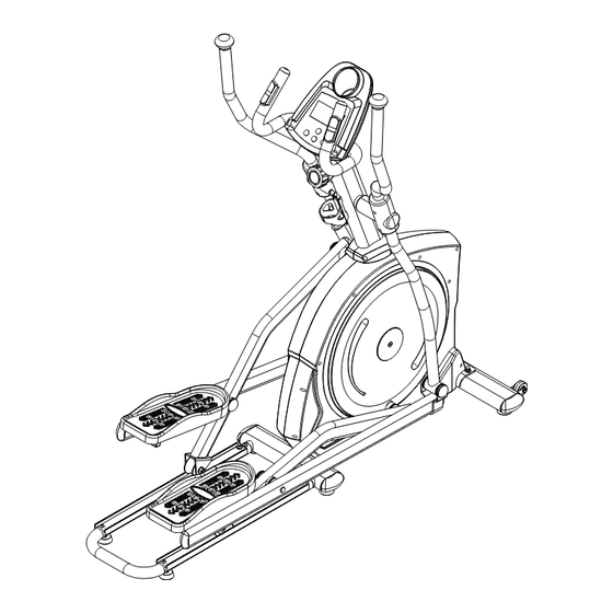
- Page 1 Pro Stride 21 Elliptical IMPORTANT: Read all instructions carefully before using this product. Retain this owner’s manual for future reference. The specifications of this product may vary from this photo, subject to change without notice. OWNER’S Item 1304 1304#130 MANUAL...
-
Page 2: Table Of Contents
TABLE OF CONTENTS SERVICE ------------------------------------------------------------------------ 2 IMPORTANT LABELS -------------------------------------------------------- 3 PRODUCT SAFETY ---------------------------------------------------------- 4 PART DRAWING -------------------------------------------------------------- 5 BOX CONTENTS ------------------------------------------------------------- 6 PART LIST ---------------------------------------------------------------------- 8 ASSEMBLY --------------------------------------------------------------------- 10 COMPUTER -------------------------------------------------------------------- 24 ADJUSTMENTS --------------------------------------------------------------- 27 TROUBLE SHOOTING & MAINTENANCE ----------------------------- 28 WARM UP ----------------------------------------------------------------------- 29 WARRANTY -------------------------------------------------------------------- 30 FAX FORM ---------------------------------------------------------------------- 31... -
Page 3: Service
SERVICE IMPORTANT: FOR NORTH AMERICA ONLY To request product service and order replacement parts, please call our customer service department at: 1-866-924-1688 Monday through Friday, 8:00 AM-5:00 PM Pacific Standard Time, service@paradigmhw.com or email us at: Please visit our website at www.paradigmhw.com. Please have the following information ready when requesting for service: Your name Phone number... -
Page 4: Important Labels
IMPORTANT LABELS... -
Page 5: Product Safety
PRODUCT SAFETY Basic precautions should always be followed, including the following safety instructions when using this equipment: Read all instructions before using this equipment. 1. Read all the instructions in this manual and do warm up exercises before using this equipment. 2. -
Page 6: Part Drawing
PART DRAWING... -
Page 7: Box Contents
BOX CONTENTS BOX A (A1) Main Body (A2) M Shape Rail Set (A3) Hand Pulse (99) Computer 1 PC 1 SET 1 SET Handlebar Set 1 SET BOX B (B4) Right Handrail Arm Set (B1) Front Stabilizer Set (B2) Front Post Set (B3) Right Foot 1 SET 1 SET... - Page 8 BOX CONTENTS BOX B INCLUDED HARDWARE & TOOLS (35) Bolt 3/8"x64mm (36) Washer 3/8"x20x2.0T (37) Cap Nut 3/8"x17T 2 PCS 4 PCS 2 PCS (43) Bolt M8x50mm (44) Nylon Nut M8x7.7T (45) Curve Washer 4 PCS 4 PCS M8x20x1.5T 4 PCS (47) Hexagon Head Bolt (48) Washer 5/16"x20x2.0T (55) Bolt M5x16mm...
-
Page 9: Part List
PART LIST Description Qty No. Description 001 Main Frame 1 030 Nut M12x11.8T 002 Front Post 1 031 Countersunk Bolt M8x20mm 003 Left Handrail Arm 1 032 Bolt M5x10mm 004 Right Handrail Arm 1 033 U Bracket 005 Left Foot Bar 1 034 Nut M6x6.0T 006 Right Foot Bar 1 035 Bolt 3/8"x64mm... - Page 10 PART LIST Description Qty No. Description 059 Hexagon Head Bolt M8x20mm 4 085 Bearing Bushing 060 Bolt M5x12mm 2 086 Bearing Fixed Bushing 061 Bolt M5x90mm 1 087 Axle Bushing 062 Nut 3/8x26 2 088 Bottle Holder 063 Left Shroud 1 089 Foot Pedal Plug Front Stabilizer End Cap 064 Right Shroud...
-
Page 11: Assembly
ASSEMBLY 1. Front Stabilizer Installation Place a block of wood to raise the main body for easier to install the Front Stabilizer (9). Position the Front Stabilizer (9) in front of Main Frame (1) and align bolt holes. Attach the Front Stabilizer (9) onto the front curve of the Main Frame (1) with two 3/8"x64mm Bolts (35), four 3/8"x20x2.0T Washers (36), and two 3/8"x17T Cap Nuts (37). - Page 12 ASSEMBLY 2. U Shape Rail Installation Place a block of wood to raise the main body for easier to install the U Shape Rail (12). Remove eight M8x20x1.5T Curve Washers (45) and eight M8x16mm Bolts (56) from the Main Frame (1). Remove bolts with the M5 Allen Wrench provided. Attach the U Shape Rail (12) onto the tubes of the Main Frame (1) with eight M8x20x1.5T Curve Washers (45) and eight M8x16mm Bolts (56) that were removed.
- Page 13 ASSEMBLY 3. Adjusting the Adjustable Leveler Turn the Adjustable Levelers (66, 91) on the Front Stabilizer (9), Main Frame (1), or U Shape Rail (12) as needed to level the elliptical trainer. The elliptical trainer has to be leveled to prevent from wobble or shaking during the exercise.
- Page 14 ASSEMBLY 4. Front Post and Tension Control Knob Installation Remove four M8x20mm Bolts (59) from the Main Frame (1). Remove bolts with the Hex Tool with Phillips Screwdriver provided. Pull out the Tension Cable (96) and Sensor Wire II (94) from the Main Frame (1).
- Page 15 ASSEMBLY 5. Lubricating the Horizontal Axle and Crank Axle Put some lubricants onto both horizontal axles of the Front Post (2) and both axles of the Crank (11). Remark: Gently apply lubricant evenly on Front Post (2). Brush tool is recommended.
- Page 16 ASSEMBLY 6. Right and Left Foot Bar Sets Installation Remove the tape from the joint of the Right Handrail Arm (4). Insert the Right Handrail Arm (4) all the way onto the horizontal axle of the Front Post (2) and secure the Right Handrail Arm (4) in position with one M8x16mm Hexagon Head Bolt (47) and one 5/16"x20x2.0T Washer (48).
- Page 17 ASSEMBLY Remove one M8x92 Bolt (39), one M8x7.7T Nylon Nut (44), and one 5/16”x20x2.0T Washer (48) from the Right Foot Bar (6). Remove bolt and nylon nut with the Hex Tool with Phillips Screwdriver and M5 Allen wrench provided. Pull the Right Foot Bar (6) up onto the Right Handrail Arm (4) and align bolt holes.
- Page 18 ASSEMBLY Tool: Allen Wrench (M5) Hex Tool with Phillips Screwdriver (13mm) CORRECT INCORRECT...
-
Page 19: Bolt M8X50Mm
ASSEMBLY 7. Left and Right Handrails Installation Attach the Left/Right Handrails (13, 14) into the Left/Right Handrail Arms (3, 4) with four M8x50mm Bolts (43), four M8x7.7T Nylon Nuts (44), and four M8x20x1.5T Curve Washers (45). Tighten nylon nuts with the Hex Tool with Phillips Screwdriver provided. - Page 20 ASSEMBLY 8. Hand Pulse Handlebar Installation Insert the Sensor Wire I (93) from the Front Post (2) into the hole on the Hand Pulse Handlebar (15) and then pull it out from the Hand Pulse Handlebar (15). Attach the Hand Pulse Handlebar (15) onto the Front Post (2) with two M8x25mm Bolts (106).
-
Page 21: Bolt M5X16Mm
ASSEMBLY 9. Left/Right Front Post Decorative Covers Installation Attach the Left/Right Front Post Decorative Covers (68, 69) onto the Front Post (2) with two M5x16mm Bolts (55). Tighten bolts with the Hex Tool with Phillips Screwdriver provided. Tool: Hex Tool with Phillips Screwdriver Hardware: (55) Bolt M5x16mm 2 PCS... - Page 22 ASSEMBLY 10. Handrail Arm Decorative Covers-A/B Installation Attach the Handrail Arm Decorative Cover-A (78) and Handrail Arm Decorative Cover-B (79) onto the Left Handrail Arm (3) with four M5x16mm Bolts (55). Tighten bolts with the Hex Tool with Phillips Screwdriver provided.
- Page 23 ASSEMBLY 11. Bottle Holder Installation Remove two M5x12mm Bolts (60) from the Front Post (2). Remove bolts with the M4 Allen Wrench provided. Attach the Bottle Holder (88) onto the Front Post (2) with two M5x12mm Bolts (60) that were removed. Tighten bolts with the M4 Allen Wrench provided.
- Page 24 ASSEMBLY 12. Computer Installation Remove four M5x10mm Bolts (32) from the back of the Computer (99). Remove bolts with the Hex Tool with Phillips Screwdriver provided. Connect the Sensor Wire I (93) and Hand Pulse Sensor Wires (97) to the wires that come from the Computer (99) and then attach the Computer (99) onto the top end of the Hand Pulse Handlebar (15) with four M5x10mm Bolts (32) that were removed.
-
Page 25: Computer
COMPUTER BUTTON FUNCTIONS: MODE: Press the "Mode" button to change modes and to confirm setup. SET: Used to set the values for TIME, DISTANCE, CALORIES and PULSE. You can hold the button to increase the value at a faster rate. (Only works while machine is stopped.) RESET: "Reset"... - Page 26 COMPUTER SET UP TIME: 1. After installing 2 AA batteries the screen will display the following (see Drawing A) and make a short high pitched sound. Drawing A 2. The calendar display will blink on and off as shown in "Drawing B". You are able to press the SET button to change the numbers.
- Page 27 COMPUTER 3. CALORIES mode: Count down - With preset calories, calories will count down from the preset value to 0. Preset values are chosen in 10 calorie increments, between 10 to 9990 calories. 4. PULSE mode: Preset values are chosen in 10 BPM (Beats Per Minute) increments, between 30 to 240 BPM.
-
Page 28: Adjustments
ADJUSTMENTS Tension Control Knob Adjusting the Tension Control Knob To increase the load, turn the tension control knob in a clockwise direction. To decrease the load, turn the tension control knob in a counterclockwise direction. Adjustable Leveler Adjusting the Adjustable Leveler Turn the adjustable leveler on the front stabilizer, main frame, or U shape rail as needed to level the elliptical trainer. -
Page 29: Trouble Shooting & Maintenance
TROUBLE SHOOTING & MAINTENCE TROUBLE SHOOTING Computer not working correctly Check to make sure the computer cable is connected securely. Make sure the batteries are installed correctly. Make sure the batteries are not dead. The elliptical trainer wobbles when in use Turn the adjustable leveler on the front stabilizer, main frame, or U shape rail as needed to level the elliptical trainer. -
Page 30: Warm Up
WARM UP Quadriceps Stretch With one hand against a wall for balance, reach behind you and pull your right foot up. Bring your heel as close to your buttocks as possible. Hold for 15 counts and repeat with left foot up. Inner Thigh Stretch Sit with the soles of your feet together with your knees pointing outward. -
Page 31: Warranty
WARRANTY Paradigm Health & Wellness, Inc. warrants to the original purchaser that this product is free from defects in material and workmanship when used for the purpose intended, under the conditions that it has been installed and operated in according to Paradigm’s Owner’s Manual. -
Page 32: Fax Form
FAX FORM PARADIGM PARTS REQUEST FAX FORM Please fax this form to (1-626-810-2166) OR YOU CAN EMAIL CUSTOMER SERVICE REQUESTS TO service@paradigmhw.com NAME: _______________________________________________________ ADDRESS: ____________________________________________________ CITY ______________ STATE ______________ ZIP ___________________ TELEPHONE: (Day) _____________________________________________ (Night) ____________________________________________ (Email Address) ____________________________________ SERIAL#: __________________________________________ MODEL#: __________________________________________ PURCHASE DATE: ______________________________________________...
Need help?
Do you have a question about the Pro Stride 21 and is the answer not in the manual?
Questions and answers