Table of Contents
Advertisement
Quick Links
PSG
1700, Léon-Harmel
Québec (Québec)
G1N 4R9
Installation and operating instructions
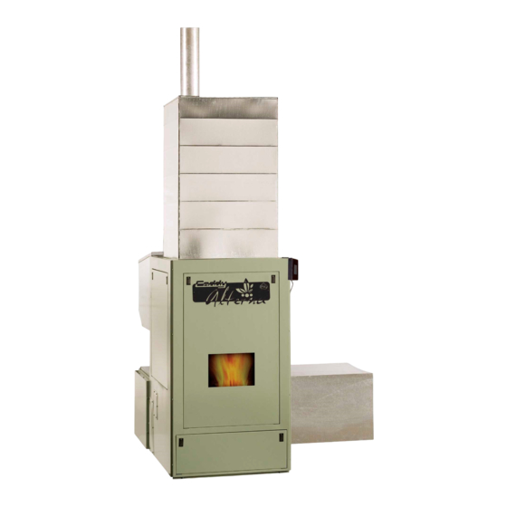
For the CADDY ALTERNA pellet furnace
READ THE MANUAL THOROUGHLY
BEFORE OPERATING THE FURNACE
TH
CERTIFIED ACCORDING TO CAN/CSA B366.1 M91,UL391 4
EDITION 2006,
RD
CAN/CSA C22.2 NO.236-05, UL 1995 3
EDITION 2003
FURNACE MODELS INCLUDED IN THIS MANUAL
CADDY ALTERNA PELLET AND 15kW/20kW COMBINATION
FURNACE
Read these instructions carefully before installing and operating
your furnace.
CONGRATULATIONS!
You have purchased one of the finest pellet
or combination furnaces available on the market.
We are confident that your furnace will provide years of comfort and safe
operation.
Please keep this document!
45406E
03/05/2009
Advertisement
Table of Contents

Related Manuals for PSG CADDY ALTERNA


Summary of Contents for PSG CADDY ALTERNA
- Page 1 1700, Léon-Harmel Québec (Québec) G1N 4R9 Installation and operating instructions For the CADDY ALTERNA pellet furnace READ THE MANUAL THOROUGHLY BEFORE OPERATING THE FURNACE CERTIFIED ACCORDING TO CAN/CSA B366.1 M91,UL391 4 EDITION 2006, CAN/CSA C22.2 NO.236-05, UL 1995 3 EDITION 2003...
- Page 2 SAFETY PRECAUTIONS • • Do not operate your furnace if you smell Keep foreign objects out of the smoke coming from it. Turn it off, monitor it, and hopper. call your dealer. • • Never use gasoline, gasoline-type Do not throw this manual away. This lantern fuel, kerosene, charcoal lighter fluid, or manual has important operating and similar liquids to start or “freshen up”...
-
Page 3: Table Of Contents
TABLE OF CONTENTS PELLET OR PELLET/ELECTRIC COMBINATION FURNACES ............. 5 1. SAFETY RULES ............................. 5 GENERAL REQUIREMENTS ........................5 ODOUR FROM THE PAINT ........................5 ASH DISPOSAL ............................5 CREOSOTE BUILD-UP AND REMOVAL ....................6 SOOT AND FLY ASH ..........................6 SMOKE DETECTOR .......................... - Page 4 AUGER MOTOR ............................. 43 GENERAL WIRING DIAGRAM ....................44 8. WIRING DIAGRAM WITH OPTIONAL ELECTRICAL ELEMENT .......... 46 9. CADDY ALTERNA TECHNICAL DATA ..................47 GENERAL TECHNICAL DATA ......................47 TECHNICAL DATA – ELECTRICAL ELEMENT ................47 TECHNICAL DATA – OTHER COMPONENTS ................... 47...
- Page 5 IMPORTANT NOTE: THE INSTALLATION OF THIS CENTRAL HEATING SYSTEM MUST BE PERFORMED BY A QUALIFIED TECHNICIAN. PSG RESERVES ITSELF THE RIGHT TO VOID ITS WARRANTY OR DENY TECHNICAL ADVICE IF THE FURNACE HAS NOT BEEN SOLD OR INSTALLED BY A PROFESSIONAL.
-
Page 6: Pellet Or Pellet/Electric Combination Furnaces
PELLET OR PELLET/ELECTRIC COMBINATION FURNACES The Caddy Alterna furnace was tested using the guidelines of the EPA Standard. To optimize the efficiency of your furnace, here are a few advices you should follow when installing or operating your Caddy Alterna. -
Page 7: Creosote Build-Up And Removal
The glass is made of 3/16” (5mm) thick Pyroceram. Do not operate your furnace with a broken glass, as this could seriously damage your furnace and cause ashes to be dispersed through the ductwork. You can purchase a replacement glass from your PSG dealer. -
Page 8: Ash Drawer
ASH DRAWER Your furnace is equipped with an ash drawer to collect ashes produced by the combustion of pellets. This drawer must not be left open during combustion as this may cause ash dispersion through the ductwork. The drawer must be emptied regularly. Once clean-up is completed, use an ash vac to carefully remove any ash around the drawer. - Page 9 Remove the screws from the hopper support (keep the screws). Loosen screws inside the hopper. Lift it and pull it backwards.
- Page 10 Blower removal Remove the screws around the blower assembly. The cold air ducting support is not installed on the blower assembly. It can be installed as per configurations A, B, or C. It is supplied in the hopper.
-
Page 11: Unit Location And Fixation To The Floor
UNIT LOCATION AND FIXATION TO THE FLOOR The furnace must be installed where outside air supply is sufficient for proper combustion. In airtight houses, it might be necessary to install an outside air intake (see COMBUSTION AIR SECTION). It is highly recommended that the unit be secured to the floor in order to prevent any situation where it could tip toward the back. -
Page 12: Clearances To Combustible Materials
CLEARANCES TO COMBUSTIBLE MATERIALS N.B. This appliance must be installed according to the instructions on the unit’s certification label. DO NOT USE MAKESHIFT MATERIALS OR COMPROMISES IN THE INSTALLATION OF THIS UNIT. CEILING CEILING 60" 2" SEE NOTE* PLENUM 12" MIN 24"... -
Page 13: Venting
VENTING The Caddy Alterna is certified for use with a chimney certified to UL-103 or ULC S629M and a chimney type vent certified to UL-641 or ULC-S-609-M89 and ULC/ORD C441-M90, with 4” inner diameter. In Canada, we recommend that you use a listed pellet vent that meets the ULC S-609-M89 and ULC/ORD C441-M90 Standards. For the United States, we recommend that you use a listed pellet vent that meets the UL-641, 7 edition Standard. This unit can be... -
Page 14: Installation Configurations
INSTALLATION CONFIGURATIONS A. HORIZONTALLY THROUGH WALL VERTICAL ROOF VENT 90 DEGREE ELBOW FOLLOW CHIMNEY OR 45 DEGREE ELBOW FOLLOW CHIMNEY OR VENT MANUFACTURER'S VENT MANUFACTURER'S INSTRUCTIONS INSTRUCTIONS TERMINATION COLLAR WALL WALL THIMBLE THIMBLE WALL STRAP WALL STRAP CLEAN OUT CLEAN OUT MIN. - Page 15 90 DEGREE ELBOW FOLLOW CHIMNEY OR 45 DEGREE ELBOW VENT MANUFACTURER'S INSTRUCTIONS TERMINATION COLLAR WALL THIMBLE WALL STRAP CLEAN OUT MIN 1' NOTE: Follow the vent manufacturer’s instructions. 1. Position furnaces, adhering to clearances. 2. Locate position of hole in wall; since most furnaces are installed in a basement, make sure that the hole in the wall is located above ground level.
- Page 16 B. VERTICALLY WITH NEW CHIMNEY SYSTEM NOTE: Follow the vent manufacturer’s instructions. OPTION: In order to vent the furnace at the right location, a 45º elbow can be used to offset the pipe from the exhaust outlet toward the appropriate location underneath the ceiling. 1.
- Page 17 C. VERTICALLY INTO EXISTING CHIMNEY SYSTEM As an alternative, the 4” vent can be run inside existing chimney to termination. NOTE: Follow the vent manufacturer’s instructions. 1. Have the chimney inspected by a qualified chimney sweep or installer to determine its structural condition. 2.
-
Page 18: Horizontal And Vertical Vent Chart
APPENDIX A HORIZONTAL AND VERTICAL VENT CHART If you plot your venting Possible Vertical system configuration on vent length this chart, your wall or roof termination should be within the grid. Possible Horizontal vent length (feet) Let’s imagine an installation consisting of a 4-feet vertical rise, a 90-degree elbow, followed by a 7-feet horizontal run through the wall, ending with a termination cap. -
Page 19: Combustion Air
COMBUSTION AIR When the furnace and the chimney are completely cold, it may be necessary to provide fresh air by opening a door or a window for a few minutes while lighting the fire. Take note that a house constructed or renovated in order to be airtight may lack the amount of fresh air necessary for the proper combustion of a solid-fuel heating appliance. -
Page 20: Installing Pc Board #2
NOTE: It is recommended to install an outside air inlet with a diameter of at least 5 inches in the room where the heating appliance is installed (see drawing below). It is preferable to choose a wall which is not exposed to dominant winds, depending on the conditions surrounding your house. - Page 21 BLACK AND WHITE WIRES PC BOARD #1 IS LOCATED BEHIND THIS PANEL...
-
Page 22: Installing The Lcd User Interface
INSTALLING THE LCD USER INTERFACE The LCD user interface (touchscreen) is used for the system’s operation. It must be attached to the bracket already installed on the furnace. Then, connect PC board #1 to the LCD user interface. In order to do so, use the white cable already connected to PCB#1. -
Page 23: Temperature Probe Connection (Rtd)
TEMPERATURE PROBE CONNECTION (RTD) On the Caddy Alterna, a RTD has to be installed on the side of the appliance using the support provided (two holes are pre-drilled on the edge of the furnace). The RTD has to be connected to the PC board #2. The RTD is a sensor (probe type) that reads the temperature inside the hot air plenum. -
Page 24: Thermostat (S)
FAN CONTROL We recommend that the HEAT mode be programmed for the Caddy Alterna (this is done with the PC board #2). Under the HEAT mode, the distribution blower uses various speeds that are controlled by the PC board #2 based on the hot air plenum temperature. -
Page 25: Installation Of An Air Conditioning Unit
INSTALLATION OF AN AIR CONDITIONING UNIT The Caddy Alterna pellet furnace has been tested with an optional air conditioning unit. If this option is chosen, we recommend an installation as per the graphic provided below. This installation will provide the most efficient and safe operation of the air conditioning unit using the distribution blower of the Caddy Alterna furnace during summer. -
Page 26: Configuration And Operating Instructions
4. CONFIGURATION AND OPERATING INSTRUCTIONS Before you configure your system and learn how to operate it, it is important to note that your Caddy Alterna is equipped with 3 main electronic components: PC board #1, PC board #2, and the LCD user interface. PC board #1 is already attached to the furnace. -
Page 27: Pc Board #2 (System Configuration)
PC BOARD #2 (SYSTEM CONFIGURATION) On the Caddy Alterna furnace, a new electronic control was developed. This system is more polyvalent. All connections are done from the PC board #2. There are connector ports available for all components and options. -
Page 28: The Speeds
The speeds Your furnace is equipped with a 4-speed blower. Using the PC board #2, we have created 6 functional speeds. Refer to Table 2 below for the various speed configurations. Table 2 – The Speeds Speed Corresponding data STATIC PRESSURE 0.2’’... -
Page 29: Cool Mode (Air Conditioning)
Programming Make sure that your wall thermostat is well connected to the PC board #2. The main thermostat must be connected to the “WOOD MECH” port on the PC board. The electric option’s thermostat must be connected to the “USER MECH”... -
Page 30: Circ (Air Circulation)
CIRC (air circulation) Operation This mode is used to circulate air during summer. Thus you will benefit from your ducting system to circulate fresh air from your basement throughout the house. Programming In the MODE menu, select CIRC by pushing the SELECT button. Then, using the arrows buttons, choose from the different selections: TEMP, UNIT, or FAN. - Page 31 UNIT (measuring unit) By pushing the arrows, you will select the measuring unit that you wish to use (Fahrenheit or Celsius). Thereafter, temperatures will be displayed according to your selection. After two minutes of inactivity on the keyboard, the display will shut itself off. The UNIT selection has no impact on the operation of the furnace. It is simply a preference chosen by the technician or the user of the product..
-
Page 32: Lcd User Interface - Operation And Configuration
LCD USER INTERFACE – OPERATION AND CONFIGURATION Manual mode main page Thermostat mode main page Indicates that the furnace status is on manual mode = Indicates that the furnace status is on thermostat mode. The green waves indicate that the thermostat is on demand. The waves will disappear once the desired temperature is reached. Indicates the flue temperature = Indicates the BTU setting. -
Page 33: Operation Tree
OPERATION TREE Selects the language displayed on the LCD interface (french, english, or spanish) Selects the pilot mode (30 minutes, 45 minutes, always This is a non-interactive page. It will help the user Selects scale Menu Screen troubleshoot the unit if temperature displayed on the needed (verifies... -
Page 34: Choosing The Maximum Input (Btu)
CHOOSING THE MAXIMUM INPUT (BTU) Your Caddy Alterna has an input that can reach up to 120,000 BTU. Since the efficiency of the furnace is 90%, the output can be calculated by multiplying the input by 0.90. In order to reduce cycling of the furnace, the BTU input can be adjusted by the installer based on the size of the house. -
Page 35: View Statistics
VIEW STATISTICS Numerous statistics can be viewed, such as the furnace run time (i.e. the number of hours the furnace has operated since it was first used). In order to view statistics, refer to the operation tree at the beginning of this section. CHANGING F TO You can choose between... -
Page 36: General Operating Guidelines And Tips
Pellets made of wood and hay will produce more ash than straight wood pellets. The wood and hay pellets that have been tested in your Caddy Alterna consisted of 1/3 hay and 2/3 wood. Make sure that any wood and hay pellets you put in your Caddy Alterna respect that mix (+/- 10%). -
Page 37: If Your Furnace Runs Out Of Pellets
exhaust box beside the exhaust blower. If this occurs, a “UNIT OVERHEAT” codewill appear on the LCD display. If you obtain a “UNIT OVERHEAT” code, it is a sign that your furnace is getting dangerously hot. You need to clean the heat exchanger and verify the venting system. -
Page 38: Maintenance
5. MAINTENANCE MAINTENANCE OF THE EXCHANGERS AND BLOWER HOUSING The exchangers should be inspected regularly during the burning season. Easy access is provided: Before cleaning the six exchanger pipes, remove the front cover located above the combustion chamber (see drawing below). It is important to start from the top and finish at the bottom. Using the scraper, clean the six exchanger pipes. -
Page 39: Venting System Maintenance
VENTING SYSTEM MAINTENANCE REGULARLY EXAMINE THE FLUE PIPES, THE JOINTS, AND THE SEALING TRIMS TO ENSURE THAT THE SMOKE AND THE COMBUSTION GASES ARE NOT TRANSPORTED INTO THE AIR DUCTING SYSTEM. The most efficient method to sweep the venting system is using a 4-inch pellet brush. Brush downwards so ash, soot and creosote residues will come off the inner surface and fall at the bottom of the venting system where they can be removed easily. -
Page 40: Cleaning The Burn Pot
CLEANING THE BURN POT The burn pot should be kept clean and its ports should not be plugged with combustion residues. Cleaning the burn port is simple. To do so, you may use the scraper supplied with unit (in the hopper) or release the clip in front of the burn pot. -
Page 41: Cleaning The Combustion Blower
CLEANING THE COMBUSTION BLOWER The combustion blower should be removed for inspection and cleaned twice a year. To do so, remove all wing nuts below the air intake system. Vacuum thoroughly. MAINTENANCE OF THE DISTRIBUTION BLOWER The two motor bearings must be lubricated once a year using non detergent SAE 20 oil (Marathon motor only). DO NOT OVERLUBRICATE... -
Page 42: Maintenance Of The Pressure Switch Tap
High efficiency 2-ply, 3-ply, or 4-ply filters are recommended. Filters dimensions Caddy Alterna: 16” x 20” filter DOOR GASKET MAINTENANCE It is important to maintain the door gasket in good condition. After a while, the gasket might sag; a door adjustment may then be required. -
Page 43: Recommended Maintenance Schedule
RECOMMENDED MAINTENANCE SCHEDULE Use this as a guide under average-use conditions. Weekly Twice a year Annually Components or after or after +/- 500 pounds +/- 2 tons per 4 tons of pellets Burn Pot Brush Glass Clean Scrape and Heat Exchanger Tubes Vacuum* Exhaust Channels Vacuum*... -
Page 44: Replacement Parts
Any defect must be repaired without delay using genuine PSG replacement parts. You can find a complete list of replacement parts in our website at www.psg-distribution.com. -
Page 45: General Wiring Diagram
7. GENERAL WIRING DIAGRAM... -
Page 47: Wiring Diagram With Optional Electrical Element
8. WIRING DIAGRAM WITH OPTIONAL ELECTRICAL ELEMENT CADDY ALTERNA PELLET/ELECTRIC COMBINATION FURNACE CONTROL PCB FUSE TERMINAL HEATING THERMODISC ELEMENT 240V TERMINAL BLOCK N L2... -
Page 48: Caddy Alterna Technical Data
9. CADDY ALTERNA TECHNICAL DATA CADDY "G" ALTERNA "F" "E" 56 ¼” 26 ¼” 47” 21 ¼” 22” "C" 22” 29 ½” "H" 16 ¼” FLUE 4” "D" PIPE "A" "B" 500 lbs WEIGHT GENERAL TECHNICAL DATA TEMP MODEL DIRECT DRIVE... -
Page 49: Psg Limited Lifetime Warranty
*Pictures required Shall your unit or a components be defective, contact immediately your PSG dealer. Prior to your call make sure you have the following information necessary to your warranty claim treatment: •...
Need help?
Do you have a question about the CADDY ALTERNA and is the answer not in the manual?
Questions and answers