JVC GY-DV5000 Instructions Manual
Dv camcorder
Hide thumbs
Also See for GY-DV5000:
- Instructions manual (49 pages) ,
- Application note (2 pages) ,
- Quick manual (13 pages)
Table of Contents
Advertisement
Quick Links
DV CAMCORDER
GY-DV5000
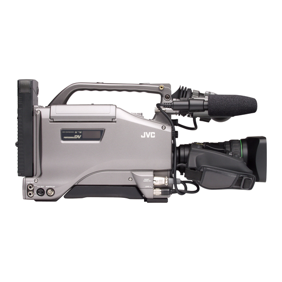
* The illustration shows the GY-DV5000 DV Camcorder with the optional lens, viewfinder, Microphone holder
and Microphone attached.
Thank you for purchasing this JVC product. Before operating
this unit, please read the instructions carefully to ensure the
best possible performance.
For Customer Use :
Enter below the Serial No. which is located on the body.
Retain this information for future reference.
Model No. GY-DV5000
Serial No.
INSTRUCTIONS
INTRODUCTION
CONTROLS,
INDICATORS AND
CONNECTORS
BASIC SYSTEM
CONNECTIONS AND
ADJUSTMENTS
POWER SUPPLY
PREPARATIONS
SETTING AND
ADJUSTMENTS
BEFORE SHOOTING
SHOOTING
OPERATION
PLAYBACK MODE
USING EXTERNAL
COMPONENTS
TIME CODE
OPERATION
MENU SCREENS
FEATURES OF THE
CAMERA SECTION
OTHERS
LWT0072-001B-H
Advertisement
Table of Contents

Subscribe to Our Youtube Channel
Related Manuals for JVC GY-DV5000


Summary of Contents for JVC GY-DV5000
- Page 1 FEATURES OF THE CAMERA SECTION OTHERS * The illustration shows the GY-DV5000 DV Camcorder with the optional lens, viewfinder, Microphone holder and Microphone attached. Thank you for purchasing this JVC product. Before operating this unit, please read the instructions carefully to ensure the best possible performance.
-
Page 2: Important Safeguards
IMPORTANT SAFEGUARDS 1. Read all of these instructions. 2. Save these instructions for later use. 3. All warnings on the product and in the operating instructions should be adhered to. 4. Unplug this appliance system from the wall outlet before cleaning. Do not use liquid cleaners or aerosol cleaners. Use a damp cloth for cleaning. -
Page 3: Safety Precautions
● Consult the dealer or an experienced radio/TV technician for help. CAUTION CHANGES OR MODIFICATIONS NOT APPROVED BY JVC COULD VOID USER’S AUTHORITY TO OPERATE THE EQUIPMENT. THIS DEVICE COMPLIES WITH PART 15 OF THE FCC RULES. -
Page 4: Main Features
● The transient section between scenes recorded on other Other use may infringe on the rights of copyright holders. ● JVC cannot assume liabilities that may derive from the units and those recorded on this unit may appear impossibility of normal recording or playback of video or disturbed. -
Page 5: Table Of Contents
CONTENTS INTRODUCTION 7. SHOOTING OPERATION 7-1 Basic Recording Operation ........52 7-2 Searching for Recorded Scenes (Edit Search) ..54 MAIN FEATURES ............... 4 7-3 If the Record-Standby Mode Continues ....55 1. INTRODUCTION 7-4 Checking Recorded Contents in Record-Standby Mode (Recording Check Function) ...... -
Page 6: Introduction
CCD elements could be serious as small white spots than the reference input (- 60 dBs) setting. may be generated. When storing the GY-DV5000 for a long ● When the unit is not in use, be sure to set the POWER switch time, the storage temperatures should be -20°C to 60°C. -
Page 7: Routine And Periodical Maintenance
1-2 Routine and Periodical Maintenance The GY-DV5000 incorporates precision mechanical parts, which will collect dirt, wear out and deteriorate as the unit is used. After the unit has been used for a long period even in a normal environment, the heads, drums and tape transport mechanisms also collect dirt. -
Page 8: Precautions For Use Of Head Cleaning Tape
1-5 Battery Pack to be Used The GY-DV5000 can use any of the following battery packs. * An Anton-Bauer battery pack cannot be connected directly ● Flat shape type to the camera. -
Page 9: Condensation
1. INTRODUCTION 1-6 Condensation ● If the unit has been cooled down in a cold place and is then ● “CONDENSATION ON DRUM” is displayed on the LCD carried to a warm place, the moisture contained in the warm monitor and in the viewfinder when condensation occurs in air may adhere to the head drum or tape guides and be cooled this unit. -
Page 10: Controls, Indicators And Connectors
2. CONTROLS, INDICATORS AND CONNECTORS 2-1 Front Section [LENS] Lens control connector Connect 12-pin lens control cable from lens here. Pin No. Function Pin No. Function Return switch Iris position VTR trigger IRIS A/R INPUT EXTENDER position Lens AUTO/MANU control ZOOM position IRIS control —... - Page 11 2. CONTROLS, INDICATORS AND CONNECTORS [AUTO WHITE/ACCU FOCUS] switch White Balance: ● First, position a white object to occupy 80% of the centre of the screen. ● When the WHT.BAL switch on page 13 is set to A or B, setting this switch to the upper position (“AUTO WHITE”) will provide automatic adjustment for white balance.
-
Page 12: Right Side Section
2. CONTROLS, INDICATORS AND CONNECTORS 2-2 Right Side Section [Camera Setting Section] EDITSEARCH MONITOR FILTER 3200K 5600K 5600K 5600K 1 64 / ND STATUS SHUTTER MENU AUDIO LEVE AUTO IRIS FULL AUTO BLACK LOLUX CH-1 CH-2 MODE BACK L STRETCH NORMAL NORMAL SPOT L... - Page 13 2. CONTROLS, INDICATORS AND CONNECTORS [BLACK] Black stretch/black compression switch [OUTPUT] Color bar/Camera/Auto knee switch Switches the gain for the dark section of the image. This switch is used to select the output signal. When the Set to an appropriate position depending on the video signal video signal from the shooting camera is selected, the auto to be shot.
- Page 14 2. CONTROLS, INDICATORS AND CONNECTORS 2-2 Right Side Section (Cont’d) LCD BRIGHT DISPLAY AUDIO PULL LEVEL OPEN OPEN FRONT EDITSEARCH REAR MONITOR CH-1 CH-2 CH-1 CH-2 FILTER 3200K AUDIO INPUT 5600K 5600K AUDIO SELECT 5600K 1 64 / ND CH-1 CH-2 STATUS AUTO...
- Page 15 2. CONTROLS, INDICATORS AND CONNECTORS View with cover open. LCD BRIGHT DISPLAY MONITOR SELECT COUNTER CH-1 OPEN FRONT CH-2 REAR EDITSEARCH MONITOR AUDIO CH-1 CH-2 FILTER CH-1 CH-2 3200K LEVEL AUDIO INPUT 5600K 5600K AUDIO SELECT AUDIO INPUT 5600K 1 64 / ND CH-1 CH-2...
-
Page 16: Left Side Section
2. CONTROLS, INDICATORS AND CONNECTORS 2-3 Left Side Section PUSH FRONT AUDIO IN LINE OUT CH-1 LENS Y/C OUT MONITOR OUT CH-2 e w q [MONITOR OUT] Monitor output connector (BNC) [CH1/CH2 LINE OUT] CH1/CH2 line output ● Composite video signal output connector. connector (RCA) ●... -
Page 17: Top Section
2. CONTROLS, INDICATORS AND CONNECTORS 2-4 Top Section BLANK SEARCH STOP PLAY STILL !0 o y Cassette cover [PLAY] button The cassette cover can be opened by sliding the OPEN Press to start playback. During still picture playback and knob . -
Page 18: Rear Section
DC OUT CH-2 [TALLY] Tally lamp Signal This lamp lights up when the GY-DV5000 enters the record mode. It blinks during the transition to the record mode. — ● Use the BACK TALLY item on the OTHERS (2/2) menu —... - Page 19 BREAKER button before turning the power ON again to put the camera in the operating status. If the unit still does not work normally, please consult the person in charge of professional video equipment at your nearest JVC-authorized service agent.
-
Page 20: Indications On The Lcd Monitor And In The Viewfinder
2. CONTROLS, INDICATORS AND CONNECTORS 2-6 Indications on the LCD Monitor and in the Viewfinder In addition to showing the EE image and the playback picture, the LCD monitor and viewfinder are also used for the following character displays. To show characters on the LCD monitor, press the DISPLAY button briefly. Status screens (screens for checking the current camera settings) Alarm message display Auto white display (only displayed in the Camera mode) - Page 21 2. CONTROLS, INDICATORS AND CONNECTORS Status Screens in the Camera Mode FULL AUTO 00:00:00:00 20min GAIN 6dB( L : 0 M : 9 H : 1 8 ) SHUTTER 1/1000 SKIN AREA WHITE BAL IRIS LVL. NORMAL –3dB –3dB FILTER 3200K ZEBRA 70–80%...
- Page 22 2. CONTROLS, INDICATORS AND CONNECTORS 2-6 Indications on the LCD Monitor and in the Viewfinder (Cont’d) ● Status 1 In addition to the information on the Status 0 screen, this screen displays the following items. Item Contents Time Code (TC)/User’s Bits (UB) indication Indicates the time code (h:m:s:frame) or user’s bits data.
- Page 23 2. CONTROLS, INDICATORS AND CONNECTORS ● Status 2 This screen displays the camera setup statuses. Event display is not available while this screen is displayed. Indication Indication Contents FULL AUTO ON, OFF GAIN –3 dB, 0 dB, 3dB, 6 dB, 9 dB, 12 dB, 15dB, 18 dB, LOLUX, ALC SHUTTER OFF, 1/7.5, 1/15, 1/30, 1/60, 1/100, 1/250.
- Page 24 2. CONTROLS, INDICATORS AND CONNECTORS 2-6 Indications on the LCD Monitor and in the Viewfinder (Cont’d) Item Contents Time/Date indication Recorded data are displayed during playback, fast forward, and rewind. During recording, the data from the DV connector is displayed. In the stop mode, the current data is displayed.
- Page 25 2. CONTROLS, INDICATORS AND CONNECTORS Alarm Message Display ● The following alarm messages are displayed while the Status(0, 1, 3) screen is shown in the Camera mode, or a status screen is shown in the VTR mode. If an alarm is generated while the Status 2 screen is shown, the Status 0 screen returns to display the alarm.
- Page 26 2. CONTROLS, INDICATORS AND CONNECTORS 2-6 Indications on the LCD Monitor and in the Viewfinder (Cont’d) Auto White Balance Indication (Camera mode only) The AUTO WHITE indication and the result of the operation are displayed during the auto white balance adjustment operation. See “Auto White Balance Adjustment”...
-
Page 27: Lens (Optional)
2. CONTROLS, INDICATORS AND CONNECTORS 2-7 Lens (Optional) [S14 x 7.3B12] IRIS mode switch A : Activates the auto iris feature. M : Allows manual iris control. Momentary auto iris button When the IRIS MODE switch is at “M”, pushing this button activates the Auto Iris Function while it is held down only. -
Page 28: Inch Viewfinder (Optional)
2. CONTROLS, INDICATORS AND CONNECTORS 2-8 1.5-Inch Viewfinder (Optional) [VF-P115B] Stopper screw This screw prevents the viewfinder from coming off the camera. Mounting guide To attach on the camera. Connector Connect to the camera. [CONT] contrast adjustment To adjust the contours of the viewfinder image. [BRIGHT] brightness adjustment To adjust the brightness of the viewfinder. -
Page 29: Basic System Connections And Adjustments
S17 × 6.6BRM(FUJINON) BATTERY CHARGER S20 × 6.4B12U(FUJINON) YH16 × 7K12U(CANON) Non-linear Editing SYSTEM TRIPOD BASE YH19 × 6.7K12U(CANON) KA-550U GY-DV5000 STANDARD PACKAGE VC-710 ( 5m ) AC POWER ADAPTER ( BATTERY CHARGER ) AA-P250 FOCUS MANUAL UNIT DV VTR... -
Page 30: Attaching The Zoom Lens
Hole back focus. ● Set the GY-DV5000's power switch to “OFF” before the zoom lens is attached or detached. When unplugging the cable connector, first remove the lens itself. Then grasp this portion and pull out. -
Page 31: Attaching The Microphone (Provided)
3. BASIC SYSTEM CONNECTIONS AND ADJUSTMENTS 3-4 Attaching the Microphone (Provided) Connect the provided microphone to the viewfinder. The 1.3. provided microphone is a phantom microphone. Loosen the stopper screw on the viewfinder. Attach the microphone to the attachment guide on the viewfinder as illustrated. -
Page 32: Attaching The Tripod Base (Provided)
3. BASIC SYSTEM CONNECTIONS AND ADJUSTMENTS 3-6 Attaching the Tripod Base (Provided) Use the provided KA-550U tripod base to place the camera on a tripod. Attach the tripod base on the tripod by using the hole that balances the unit most optimally. While pushing the safety lever, pull the lock lever toward Tripod mounting holes the front until the front mount clip clicks into place. -
Page 33: Power Supply
DC power is applied. Then switch ON again. ● If the GY-DV5000 is left with the battery pack attached, a small amount of power is consumed even if the POWER switch on the GY-DV5000 is set to OFF. Remove the battery pack when the GY-DV5000 is not going to be used. - Page 34 4. POWER SUPPLY 4-2 Battery Pack Operation (Optional) (Cont’d) Using a Flat Shape Type Battery Pack (optional) Attaching a Flat Shape Type Battery Pack Open the battery case cover while pushing the lock release lever. Insert the battery pack into the battery case with its electrodes facing the unit.
- Page 35 To use an Anton-Bauer battery pack (Propack 13/14, Trimpack 13/14, Magnum 13/14, Compack 13/14 Series), it is necessary to detach the battery case from the GY-DV5000 and replace it with the Anton-Bauer battery holder. Use the following battery holder. • Battery holder: Anton-Bauer QRQ27...
-
Page 36: Remaining Battery Power Display
BATT lamp and TALLY lamp: Blinks BACK TALLY lamp on camera: Blinks Monitoring loudspeaker and PHONES jack: Alarm sound Viewfinder After the remaining battery power warnings appear, the GY-DV5000 automatically stops operation if the battery LOW VOLTAGE power operation is continued. 10.5V Battery lamp... -
Page 37: Preparations
Operation Camera mode The GY-DV5000 enters the record mode. The camera image is displayed in the viewfinder or on the LCD monitor. When a recordable videocassette is loaded, the GY-DV5000 enters the record-standby mode automatically. “STBY” is displayed in the VTR operation mode indication area of the LCD monitor or in the viewfinder. -
Page 38: Cassette Loading And Unloading
Cassette cover ● A cassette cannot be loaded or unloaded while the GY-DV5000 is in POWER OFF mode. ● Use a standard DV videocassette or a MiniDV videocassette. ● Press at the center portion of the cassette back and insert the cassette tape straight into the slot. - Page 39 5. PREPARATIONS OPEN knob Cassette cover EJECT button Cassette cover Unloading the Cassette Set the POWER switch to ON. Slide the OPEN knob to the side to open the cassette cover. Press the EJECT button. Tape ejection starts. MEMO: It takes a few seconds before the cassette is ejected after the EJECT button is pressed.
-
Page 40: Viewing The Lcd Monitor
5. PREPARATIONS 5-3 Viewing the LCD Monitor The LCD monitor’s orientation, angle, and brightness, etc. can be changed. LCD lock and release knob LCD door Opening the LCD monitor Slide the LCD lock and release knob toward the rear section to open the LCD monitor. -
Page 41: Setting, Displaying And Recording The Date And Time
5. PREPARATIONS 5-4 Setting, Displaying and Recording the Date and Time The date and time of the built-in clock should be set. Powered by the built-in backup battery the set date and time data continue to count even when the power is switched off. ●... - Page 42 5. PREPARATIONS 5-4 Setting, Displaying and Recording the Date and Time (Cont’d) TIME/DATE menu screen Display the screen for setting the date and time. Rotate the SHUTTER dial to align the cursor ( ) with the ––– TIME/DATE ––– CLOCK ADJUST item, and then press the SHUTTER dial. DISPLAY ●...
-
Page 43: Displaying The Time And Date On The Screen
5. PREPARATIONS Displaying the Time and Date on the Screen Whether or not the time and date should be displayed on the screen and how to display them are set on the TIME/DATE TC/UB/CLOCK menu screen menu screen. ––– TC/UB/CLOCK ––– Display the TIME/DATE menu screen. -
Page 44: Charging The Built-In Battery
In this case, recharge the built-in battery and then set the date and time and time code data again. However, it is possible to use the GY-DV5000 even if the bulit-in battery is discharged but the date and time and time code data cannot be recorded. -
Page 45: Setting And Adjustments Before Shooting
6. SETTING AND ADJUSTMENTS BEFORE SHOOTING 6-1 Camera Settings POWER SUPPLY 1 First place a charged battery pack in the battery case on the rear section of the unit. If battery pack is not used, connect DC power to the DC INPUT connector on the OPEN EDITSEARCH rear section of the unit using the AC power adapter (AA-... -
Page 46: Viewfinder Adjustment
Color video monitor Connect a color video monitor to the MONITOR OUT connector of the GY-DV5000. Set the COLOR BARS/CAMERA/AUTO KNEE switch to BARS to output the color bar signal (SMTPE type color bars). -
Page 47: Back Focus Adjustment
6. SETTING AND ADJUSTMENTS BEFORE SHOOTING 6-5 Back Focus Adjustment It is only necessary to perform this when the lens is attached 4. 6. for the first time or when focusing is not correct in both the telephoto and wide-angle positions. It is easier to adjust back focus when the subject is more than 3 meters from the camera. -
Page 48: White Balance Adjustment
6. SETTING AND ADJUSTMENTS BEFORE SHOOTING 6-6 White Balance Adjustment Since the color of light (color temperature) varies depending on the light source, it is necessary to re-adjust the white balance when the main light source illuminating the subject changes. Note When a subject illuminated by a halogen lamp with a color temperature of 3,200K is shot while the color temperature conversion filter setting is set to 5,600K, 5,600K+1/8 ND, or 5,600K+1/64 ND, a proper white balance adjustment and (FAW) Full Time... -
Page 49: Audio Input Signal Selection
MANUAL +48V PRST (LINE/MIC) switch The GY-DV5000 is provided with the FRONT AUDIO IN Selecting the FRONT AUDIO IN connector and REAR connector and the REAR AUDIO IN connector for audio input. AUDIO IN connector Two channels of sound can be recorded on the tape in digital Select the sound to be input to the AUDIO INPUT connector PCM format. -
Page 50: Recording Level Adjustment
6. SETTING AND ADJUSTMENTS BEFORE SHOOTING 6-8 Recording Level Adjustment LCD BRIGHT DISPLAY OPEN AUDIO EDITSEARCH PULL MONITOR LEVEL OPEN FILTER FRONT 3200K 5600K REAR 5600K CH-1 CH-2 5600K 1 64 / ND CH-1 CH-2 STATUS SHUTTER AUDIO INPUT AUDIO SELECT LCD BRIGHT DISPLAY CH-1... -
Page 51: Monitoring Audio During Recording
6. SETTING AND ADJUSTMENTS BEFORE SHOOTING 6-9 Monitoring Audio during Recording MONITOR SELECT switch LCD BRIGHT DISPLAY MONITOR SELECT COUNTER CH-1 FRONT CH-2 REAR AUDIO CH-1 CH-2 CH-1 CH-2 LEVEL AUDIO INPUT OPEN AUDIO SELECT AUDIO INPUT CH-1 CH-2 TC GENE. FRONT REAR EDITSEARCH... -
Page 52: Shooting Operation
7-1 Basic Recording Operation OPEN knob Set the POWER switch to ON. ● Power is supplied to the unit. The CAM indicator lights up. The GY-DV5000 is in the Camera mode when the CAM indicator is on. OPEN EDITSEARCH MONITOR... - Page 53 ● If the VTR trigger button is pressed very quickly and repeatedly, or the POWER switch is moved immediately after the trigger button is pressed, the viewfinder REC indicator lamp may blink and the GY-DV5000 may not enter the record mode. To remedy this condition set the POWER switch to OFF and wait for 5 seconds or more before turning the power on again.
-
Page 54: Searching For Recorded Scenes (Edit Search)
7. SHOOTING OPERATION 7-2 Searching for Recorded Scenes (Edit Search) In the record-standby mode, it is possible to search for a scene when you want to check the recorded scene or continue recording from the scene. EDITSEARCH EDIT SEARCH OPEN + button EDITSEARCH MONITOR... -
Page 55: If The Record-Standby Mode Continues
01/02/03 AM01:23:45 VTR mode indication 7-4 Checking Recorded Contents in Record-Standby Mode (Recording Check Function) This function is available only when the GY-DV5000 is in the RET button standby mode. In the record-standby mode, approximately 2 seconds of the last recorded portion can be played back. -
Page 56: Recording The Color Bars
7. SHOOTING OPERATION 7-5 Recording the Color Bars OUTPUT switch OPEN EDITSEARCH MONITOR FILTER 3200K 5600K 5600K 5600K / ND 1 64 STATUS SHUTTER POWER LCD BRIGHT DISPLAY MENU AUDIO PULL LEVEL OPEN FRONT REAR AUTO IRIS FULL AUTO BLACK LOLUX CH-1 CH-2... -
Page 57: Playback Mode
POWER switch MODE switch MEMO: MEMO: ● The GY-DV5000 can play back the following three types ● In the VTR mode, the camera image is not output on the of videocassettes: LCD monitor, in the viewfinder or through the video output •... -
Page 58: Fast-Forward, Rewind
8. PLAYBACK MODE BLANK SEARCH STOP PLAY STILL OPEN EDITSEARCH MONITOR FILTER 3200K 5600K 5600K 5600K 1 64 / ND STATUS SHUTTER LCD BRIGHT DISPLAY MENU AUDIO PULL LEVEL OPEN FRONT REAR AUTO IRIS FULL AUTO BLACK LOLUX CH-1 CH-2 CH-1 CH-2 MODE... -
Page 59: Outputting Ch-3, Ch-4 Channel Audio
CH-1 and CH-2. (4-channel recording is possible in the case of DV input.) When the GY-DV5000 is used for playback of a tape that was recorded on another unit with audio recorded on the CH-3 and CH- 4 channels, the AUDIO SELECT item on the AUDIO/VIDEO menu screen must be set. -
Page 60: Using External Components
9. USING EXTERNAL COMPONENTS 9-1 Connecting a Video Component with DV Connector Connecting the GY-DV5000 to another video component equipped with DV I/O connector (IEEE1394 standard) using a DV cable (optional) enables dubbing of digital signals with high picture quality and high-quality sound. - Page 61 Backup Recording of the GY-DV5000's Camera Image and Sound Through the DV Connector The GY-DV5000’s camera image and sound can be recorded for backup on another component that is equipped with DV connector. Recording operation is performed on the backup equipment simultaneously with performance of the recording operations on the GY-DV5000.
-
Page 62: Time Code Operation
10. TIME CODE OPERATION The GY-DV5000 records SMPTE-standard time codes and user’s bits. In the play mode or the record mode, the reproduced time codes or user’s bits are shown on the LCD monitor or in the viewfinder. ● Time code data cannot be output through the unit’s connectors. -
Page 63: Time Code Presetting Procedure
10. TIME CODE OPERATION TIME CODE PRESETTING PROCEDURE The time code and user’s bit data are preset on the TC/UB/ CLOCK menu screen. Display the TC/UB/CLOCK menu screen. 1 Press the Status button for 1 second or more to display OPEN EDITSEARCH the TOP MENU screen. -
Page 64: Recording Time Codes In Continuation Of Time Codes Recorded On Tape
TC GENE switch 10-4 Reproducing Time Codes The GY-DV5000 incorporates a time code reader. During playback, the time code or user’s bit data recorded on the tape is displayed on the LCD monitor or in the viewfinder. (Status screen) Setting Playback time code indication See “Displaying Time Code”... -
Page 65: Menu Screens 11-1Menu Screen Configuration
The FILE MANAGE menu screen can be used to store the menu setting contents in two types of files (FILE CAM1, FILE CAM2) on the GY-DV5000. When saving menu setting contents that remain more or less fixed, these are stored in FILE CAM1 or FILE CAM2. -
Page 66: Setting Menu Screens
CH-1 CH-2 SPOT L COMPRESS AUTO MANUAL Set the mode of the GY-DV5000 with the MODE switch. (Camera mode or VTR mode) POWER Press the STATUS button for 1 second or longer. ● The TOP MENU screen appears. STATUS button Select the menu screen to be set. -
Page 67: File Manage Menu Screen
11. MENU SCREENS 11-3FILE MANAGE Menu Screen The FILE MANAGE menu screen is used to perform the following tasks. ● Storing menu setting contents in two types of files (CAM1, CAM2). When saving menu setting contents that remain more or less fixed, these are stored in CAM1 or CAM2. ●... -
Page 68: Top Menu Screen
11. MENU SCREENS 11-4TOP MENU Screen Different menu screens are displayed depending on whether the GY-DV5000 is in the Camera mode or in the VTR mode. In the VTR mode, the CAMERA OPERATION and CAMERA PROCESS menu screens are not displayed. -
Page 69: Camera Operation Menu Screen
11. MENU SCREENS 11-5CAMERA OPERATION Menu Screen The CAMERA OPERATION menu screen is only displayed in the Camera mode. Item Function Variation Range Initial Setting SHUTTER The SHUTTER button on the right side section is used to select STEP for STEP STEP fixed shutter speed or V.SCAN variable scanning rate for shooting computer... -
Page 70: Camera Process Menu Screen
11. MENU SCREENS 11-6CAMERA PROCESS MENU Screen The CAMERA PROCESS menu screen is only displayed in the Camera mode. Item Function Variation Range Initial Setting MASTER Adjusts the pedestal level (master black), which is the reference of black. MAX (10) NORMAL ●... -
Page 71: Advanced Process Screen
11. MENU SCREENS 11-7ADVANCED PROCESS Screen Item Function Variation Range Initial Setting CINE MODE When set to ON, produces gamma curve close to the picture characteristics of movies. COLOR Used to set the color matrix. When set to ON, color reproduction becomes MATRIX good. -
Page 72: Audio/Video Menu Screen
48K : Recording is performed with 16-bit, 48 kHz sampling frequency * The DV format offers recording tracks for up to 4 channel when using 12-bit, 32 kHz sampling. The GY-DV5000 records two of these track. The GY-DV5000 does not allow after-recording. -
Page 73: Lcd/Vf Menu Screen
11. MENU SCREENS 11-10 LCD/VF Menu Screen The LCD/VF menu screen consists of two screens. (1/2 screen, 2/2 screen) LCD/VF (1/2) Menu Screen Settings can be made on the LCD/VF (1/2) menu screen only in the Camera mode. Item Function Variation Range Initial Setting ZEBRA Switches the luminance level of the subject sections where the zebra... -
Page 74: Menu Screens
11. MENU SCREENS 11-10 LCD/VF Menu Screen (Cont’d) LCD/VF (2/2) Menu Screen Item Function Variation Range Initial Setting TAPE Selects whether or not the remaining tape time (minutes) is shown in the REMAIN status display on the LCD monitor or in the viewfinder. (Camera mode: Status 1 screen, VTR mode: Status screen) OFF : Not displayed. -
Page 75: Tc/Ub/Clock Menu Screen
11. MENU SCREENS 11-11 TC/UB/CLOCK Menu Screen Time codes and user’s bits can be set on this screen. Date and time is set on the screen that can be reached from this screen. Item Function Variation Range Initial Setting TC PRESET To preset the time code, align the cursor with this position and then press EXECUTE EXECUTE... -
Page 76: Time/Date Menu Screen
11. MENU SCREENS 11-12 TIME/DATE Menu Screen Item Function Variation Range Initial Setting DISPLAY Sets whether the date and time are shown in the status display on the LCD monitor or in the viewfinder. OFF: Not displayed. ON : Displayed. When a tape with time and date not recorded is played back, there will be no display of time and date even when this item is set to ON. -
Page 77: Others Menu Screen
Selects whether or not the VTR trigger command should be output through TRIGGER the DV connector. Set to ON when the GY-DV5000's DV signal should be recorded on another component for backup. OFF : VTR trigger command is not output. - Page 78 11. MENU SCREENS 11-13 OTHERS Menu Screen (Cont’d) OTHERS (2/2) Menu Screen Item Function Variation Range Initial Setting ALARM VR Selects whether or not alarm sound is emitted and the volume of the HIGH LEVEL alarm sound. The alarm sound is output through the monitoring loudspeaker and the MIDDLE PHONES jack.
-
Page 79: Features Of The Camera Section
12. FEATURES OF THE CAMERA SECTION 12-1 Full-Time Auto White Balance (FAW) The FAW function adjusts the white balance ––– CAMERA OPERATION ––– value automatically as the lighting condition SHUTTER STEP changes. GAIN L GAIN M This mode is convenient when you have no time to adjust the GAIN H white balance or when the camera is moved frequently in and LOLUX GAIN... -
Page 80: Iris (Brightness) Adjustment
12. FEATURES OF THE CAMERA SECTION 12-2 IRIS (Brightness) Adjustment ADJUSTMENT OF LENS IRIS The lens iris can be adjusted using any of the following three methods. ● Automatic adjustment Iris ring Set the iris mode switch to “A” (Auto). The iris is adjusted automatically according to the brightness of the object. -
Page 81: Adjusting The Shutter Speed
12. FEATURES OF THE CAMERA SECTION 12-3 Adjusting the Shutter Speed Adjust the shutter speed to obtain special effects or when shooting scenes with slow-moving subjects. Setting Set the SHUTTER item on the CAMERA OPERATION menu screen. STEP : The shutter speed is changed in fixed steps. OPEN EDITSEARCH MONITOR... -
Page 82: Shooting The Screen Image On A Computer Monitor
12. FEATURES OF THE CAMERA SECTION 12-4 Shooting the Screen Image on a Computer Monitor Outline The following operation allows the alignment of the shutter speed of the camera with the variable scanning rate of a computer monitor or display. Band When a computer monitor screen or display is shot with the camera, a bright horizontal line indicating excessive exposure... -
Page 83: Gain (Sensitivity) Adjustment
12. FEATURES OF THE CAMERA SECTION 12-5 Gain (Sensitivity) Adjustment The gain should be switched when the brightness is insufficient due to poor lighting conditions. GAIN SWITCHING This switch allows the gain to be boosted when the illumination GAIN switch of the subject is insufficient. -
Page 84: Switch Setup According To Illumination And Subject
12. FEATURES OF THE CAMERA SECTION 12-6 Switch Setup According to Illumination and Subject Various switch settings are performed to accommodate the conditions of the illumination and the subject when shooting. SWITCH FUNCTIONS 1AUTO IRIS LEVEL switch AUTO IRIS BLACK stretch/black This switch allows the reference value for the auto iris LEVEL switch compress switch... -
Page 85: How To Use Skin Detail
12. FEATURES OF THE CAMERA SECTION 12-7 How to Use Skin Detail The contour emphasis in the skin color areas of the video signal can be controlled and made to appear gentle and smooth. Setting the Color and Range of the Skin Detail Function OPEN EDITSEARCH... - Page 86 12. FEATURES OF THE CAMERA SECTION 12-7 How to Use Skin Detail (Cont’d) Using the Skin Detail Function To use the skin detail function set on the SKIN COLOR ADJUST screen, select “ON” for the SKIN DTL DETECT item on the CAMERA PROCESS menu screen.
-
Page 87: Others
13-1 Alarm Indications and Actions The GY-DV5000 displays messages on the LCD monitor and in the viewfinder in the case of improper operation, notices on remaining battery power and tape and warnings in the case of abnormalities during VCR operation. - Page 88 In such a case, switch off the power once and switch it Warning DRUM MOTOR FAILURE on again, and then close the cassette cover before use. Error Code Error Details GY-DV5000 Operation Remedy 0201 Indicates dew formation Operation stops. All operations Leave the unit with the power ON,...
- Page 89 13. OTHERS Viewfinder Warning Lamps BATTERY lamp This red lamp lights red under the following circumstances. Lights red : When the battery voltage becomes too low for the camera to operate. REC/ALARM lamp This lamp lights or blinks green under the following conditions.
-
Page 90: Troubleshooting
The transient section between scenes recorded on other units and those recorded on the GY-DV5000 may appear disturbed. ● Is the CH1 FRONT VR item on the AUDIO/VIDEO menu screen set to The front section’s audio level control doesn’t work. -
Page 91: Hour Meter Display
13. OTHERS 13-3 Hour Meter Display The GY-DV5000 can display the accumulated running time of the head drum in the HOUR METER item on the OTHERS (2/2) menu screen. Use this as a guide for periodical maintenance. See page 7. -
Page 92: Specifications
[VIDEO] Recording format : 8-bit, 13.5 MHz, * Service parts number 4:1:1 component recording For details, consult your JVC dealer. [AUDIO] Recording format : 16-bit, 48 kHz, 2-channel PCM audio/12-bit, 32 kHz 4-channel Design and specifications are subject to change without PCM audio (2 channels for notice. - Page 93 13. OTHERS OPTIONAL ACCESSORIES Viewfinder : VF-P115B, VF-P116 : S14 × 7.3B12U, S17 × 6.6BRM, S20 × 6.4B12U (FUJINON) Power zoom lens YH16 × 7K12U, YH19 × 6.7K12U (CANON) AC power adapter : AA-P250 Microphone : MV-P615U, MV-P618U Microphone holder : KA-A50U Network Pack : KA-DV5000U...
- Page 94 VICTOR COMPANY OF JAPAN, LIMITED ® is a registered trademark owned by VICTOR COMPANY OF JAPAN, LTD. ® is a registered trademark in Japan, the U.S.A., the U.K. and many other countries. Printed in Thailand © 2002 VICTOR COMPANY OF JAPAN, LIMITED LWT0072-001B-H...
Need help?
Do you have a question about the GY-DV5000 and is the answer not in the manual?
Questions and answers