Table of Contents
Advertisement
Quick Links
Precautions For Use of the DV Connector
Be sure to follow the procedure outlined below when connecting.
1.
Turn ON the GY-DV500 and the equipment to be connected.
2.
Set the VCR Setup Menu item No. 126 INPUT SELECT.
3.
Insert the videocassette.
4.
Connect the DV cable.
( If the procedure is performed in incorrect order, noise may appear in the recording and playback picture and the
sound may fall out. If this occurs, disconnect the DV cable and then connect it again following steps
above procedure.)
When recording the GY-DV500 playback picture using another component with DV
connector, such as a non-linear editing controller, be sure to set the VCR Setup
Menu item No. 126 INPUT SELECT to IEEE1394.
1
4
(If the INPUT SELECT item is set to CAMERA, be sure to perform steps
to
of the above procedure.)
When making a backup recording on another component via the DV connector while
recording with the GY-DV500, be sure to set the VCR Setup Menu item No. 126
INPUT SELECT to CAMERA.
1
4
(If the INPUT SELECT item is set to IEEE1394, be sure to perform steps
to
of the above procedure.)
Precautions for Use of Head Cleaning Tape
Adhere to the following precautions when using the head cleaning tape.
1.
The tape runs for 10 seconds at a time in the PLAY mode. (The tape stops automatically and
then the unit enters the SAVE MODE. However, the display back light is not turned off.)
Press the PLAY button after the cleaning tape is fully loaded.
2.
Do not use the tape more than four times at the most for each cleaning.
3.
The cleaning tape can be used four times.
One time: One tape transport from the start of the rewound tape to the end of the tape.
■ Use the following chart as a guide for periodical head cleaning.
Operating
Low temperature
Room temperature
environment
0˚C to 10˚C
10˚C to 35˚C
Yardstick for use
1 to 2 times
1 to 2 times
of cleaning tape
every 5 hours
every 20 to 30 hours
Note 1) When used in a low humidity environment (10% RH to 30% RH), head cleaning should be
conducted at intervals half of those given in the above chart.
Note 2) When an ME80 tape is used immediately after head cleaning, the VTR warning (head)
indicator may remain on. In this case, let the tape run as the indicator will turn off after the
tape has run for a while.
Note 3) Use the cleaning tape in the room temperature (10˚C to 35˚C).
Precautions when writing S.S.F. data
When S.S.F. data stored in the memory of the GY-DV500 is written to the beginning of the
rewound tape, approximately 5 seconds of recorded video and/or sound will be erased at
the beginning.
In the case of important recordings, leave 5 seconds or more of the tape unrecorded
before starting recording.
1
4
to
of the
SC96935-001
High temperature
35˚C to 40˚C
1 to 2 times
every 5 hours
SC96934-001
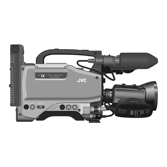
DV CAMCORDER
GY-DV500
* The illustration shows the GY-DV500 DV Camcorder with the optional lens viewfinder attached.
Thank you for purchasing this JVC product. Before operating
this unit, please read the instructions carefully to ensure the
best possible performance.
For Customer Use :
Enter below the Serial No. which is located on the body.
Retain this information for future reference.
Model No. GY-DV500
Serial No.
INTRODUCTION
CONTROLS,
INDICATORS AND
CONNECTORS
BASIC SYSTEM
CONNECTIONS AND
ADJUSTMENTS
POWER SUPPLY
PREPARATIONS
SETTING AND
ADJUSTMENTS
BEFORE SHOOTING
SHOOTING
OPERATION
PLAYBACK MODE
INSTRUCTIONS
TIME CODE
OPERATION
S.S.F. (Super Scene
Finder)
yyy
USING EXTERNAL
COMPONENTS
yyy
SETUP MENU
FEATURES OF THE
CAMERA SECTION
OTHERS
This instructions attached to service
manual is different from that which is
provided the GY-DV500.
This instruction manual is made from 100% recycled paper.
SC96874 : U-ver.
SC96875 : E-ver.
Advertisement
Table of Contents

Subscribe to Our Youtube Channel
Related Manuals for JVC GY-DV500


Summary of Contents for JVC GY-DV500
- Page 1 Note 3) Use the cleaning tape in the room temperature (10˚C to 35˚C). SC96934-001 Precautions when writing S.S.F. data When S.S.F. data stored in the memory of the GY-DV500 is written to the beginning of the rewound tape, approximately 5 seconds of recorded video and/or sound will be erased at the beginning.
-
Page 2: Safety Precautions
● Consult the dealer or an experienced radio/TV technician for help. CAUTION CHANGES OR MODIFICATIONS NOT APPROVED BY JVC COULD VOID USER’S AUTHORITY TO OPERATE THE EQUIPMENT. THIS DEVICE COMPLIES WITH PART 15 OF THE FCC RULES. -
Page 3: Table Of Contents
● The transient section between scenes recorded on other Other use may infringe on the rights of copyright holders. ● JVC cannot assume liabilities that may derive from the units and those recorded on this unit may appear impossibility of normal recording or playback of video or disturbed. -
Page 4: Introduction
14-3 Specifications ... 93 that these parts are engaged properly. • Optional Accessories ... 94 ● When moving the GY-DV500 mounted on a tripod, any • External Dimensions ... 94 impact or vibration should be avoided as this may cause the unit to become detached and to drop from the tripod. -
Page 5: Routine And Periodical Maintenance
1-3 Routine and Periodical Maintenance The GY-DV500 incorporates precision mechanical parts, which will collect dirt, wear out and deteriorate as the unit is used. On the other hand, when the unit has been used for a long period in a normal environment, the heads, drums and tape transport mechanisms also collect dirt deposited on them. -
Page 6: Controls, Indicators And Connectors
2. CONTROLS, INDICATORS AND CONNECTORS 2-1 Front Section [LENS] Lens control connector Connect 12-pin lens control cable from lens. Pin No. Lens AUTO/MANU control [ZEBRA] Switch When this switch is ON, a zebra pattern is superimposed on the viewfinder areas having video levels with a luminance level of 70% to 80%. -
Page 7: Right Side Section
When a recordable videocassette is loaded, the GY-DV500 enters the record-pause mode. SAVE: The GY-DV500 is in the save mode. • The status of the GY-DV500 is displayed on the Status screen 1 in the viewfinder. [OUTPUT] Color bar/Camera/Auto knee switch This switch is used to select the output signal. - Page 8 2. CONTROLS, INDICATORS AND CONNECTORS 2-2 Right Side Section (Cont'd) [Audio Setting Section] OPERATE/WARNING LIGHT RESET MONITOR COUNTER FILTER SELECT 1 3200k ALARM 2 5600k 3 5600k+ND SHUTTER STATUS MONITOR MENU CH-1 AUDIO CH-2 LEVEL AUTO IRIS FULL AUTO BLACK LOLUX BACK L STRETCH...
- Page 9 (Keep this switch at OFF during battery operation of the [AUD LOCK] indicator GY-DV500 or when it is required to reduce the power consumption for some reason.) Indicates whether the audio signal is locked to the video signal during recording and playback.
-
Page 10: Left Side Section
This is not a malfunction. * If the cassette cover is not closed, the GY-DV500 will • Only for the combined H (horizontal)/V (vertical) remain inoperative. -
Page 11: Rear Section
DV CAMCORDER GY-DV500 Back tally lamp This lamp lights up when the GY-DV500 enters the record mode. It blinks during the transition to the record mode. • Use the VCR Setup Menu item No. 082 BACK TALLY MODE to select whether or not the lamp should light and the lighting pattern. -
Page 12: Counter Display Contents
2. CONTROLS, INDICATORS AND CONNECTORS 2-6 Counter Display Contents The counter display shows the following 4 types of information. OPERATE/WARNING LIGHT Tape counter display CH 1 OVER AUTO OFF DEW RESET 40 30 0 dB CH 2 OVER SERVO The counter display usually functions as a tape counter HOLD MONITOR AUD LOCK... -
Page 13: Lens (Optional)
2. CONTROLS, INDICATORS AND CONNECTORS 2-7 Lens (optional) [S14 x 7.3B12] IRIS mode switch A: Activates the auto iris feature. M: Allows manual iris control. Momentary auto iris button When the IRIS MODE switch 7 is at "M", pushing this button activates the Auto Iris Function while it is held down only. -
Page 14: Indications In Viewfinder
Steady green : During recording. Lamp Lamp Blinks green : • While the GY-DV500 switches from record- VIEWFINDER SCREEN DISPLAY The following indications are displayed on the viewfinder screen. (However, this information is not displayed while the VCR section is playing back a tape.) - Page 15 2. CONTROLS, INDICATORS AND CONNECTORS 2-9 Indications in Viewfinder (Cont'd) ● Status 1 In addition to the information on the Status 0 screen, this screen displays audio indicators and information on remaining tape, voltage and lens F-number. Display position Display Shows the input level of the audio input channel.
-
Page 16: Basic System Connections And Adjustments Basic System
MIC HOLDER KA-A50 1.5" VIEW FINDER VF-P115B/115/116 MICROPHONE ZOOM LENS S14 x 7.3B12(FUJINON) S16 x 6.7B12(FUJINON) S19 x 6.5B12(FUJINON) YH14 x 7.3K12(CANON) GY-DV500 YH18 x 6.7K12(CANON) STANDARD PACKAGE FOCUS MANUAL UNIT HZ-FM13 (FUJINON) HZ-FM15 (CANON) TRIPOD TP-P300 ZOOM SERVO UNIT HZ-ZS13B... -
Page 17: Attaching The Zoom Lens (Optional)
3. BASIC SYSTEM CONNECTIONS AND ADJUSTMENTS 3-2 Attaching the Zoom Lens (optional) Loosen the mount ring. Connect the cable connector. Attach the lens with its pin aligned with the hole in the mount. Tighten the mount ring. CAUTION: Be sure to tighten the mount ring completely. Incomplete tightening may result in the lens dropping off or disturbed back focus. -
Page 18: Attaching The Tripod Base (Provided)
3. BASIC SYSTEM CONNECTIONS AND ADJUSTMENTS 3-7 Inserting and Replacing Backup Lithium Batteries The GY-DV500 uses a lithium battery for backup of the time code data. Install the provided lithium battery before actually using the unit. ● Lithium battery: CR2032 "Li"... -
Page 19: Power Supply
DC power is applied. Then switch ON again. ● If the GY-DV500 is left with the battery pack attached, a small amount of power is consumed even if the POWER switch on the GY-DV500 is set to OFF. Remove the battery pack when the GY-DV500 is not going to be used. -
Page 20: Using An Anton-Bauer Battery Pack
To use an Anton-Bauer battery pack (Propack 13/14, Trimpack 13/14, Magnum 13/14, Compack 13/14 Series), it is necessary to detach the battery case from the GY-DV500 and replace it with the Anton-Bauer battery holder. Use the following battery holder. • Battery holder: Anton-Bauer QRQ27... -
Page 21: Preparations
• The display of the VCR section is turned on. Select the GY-DV500 operation mode with the VTR switch. • The GY-DV500 operation mode may differ when the power is turned ON and when the cassette is loaded depending on the setting of the VTR switch as follows:... -
Page 22: Setting The Date And Time
5-3 Setting the Date and Time The date and time of the built-in clock should be set. During shooting, the date and time data are recorded in the sub-time code area on the tape. During playback, the data are shown on the counter display. Powered by the backup lithium battery, the set date and time data continue to count even when the power is switched off. -
Page 23: Viewfinder Adjustment
Display the camera built-in color bar signal on the video monitor and adjust the colors, contrast and brightness. Connect a color video monitor to the MONITOR OUT Connect a colour video monitor to the MONITOR OUT connector of the GY-DV500. connector of the GY-DV500. Set the OUTPUT switch to BARS to output the color bar Set the OUTPUT switch to BARS to output the colour bar signal (SMTPE type color bars). -
Page 24: White Balance Adjustment
● BACK TALLY MODE Select the lightning pattern of the BACK TALLY lamp. ● INPUT SELECT (U-ver. only) Select the input video signal. To record the GY-DV500's signal, set to "CAMERA". See page 68. ● LOW CUT IN For each audio input connector, select whether or not the lower frequency components of the audio signal are cut. -
Page 25: Audio Input Signal Selection
LEVEL REAR CH-1 AUDIO INPUT switch The GY-DV500 is provided with the microphone connector on Selecting the front section's microphone connector the front section and the two AUDIO INPUT connectors at the A microphone (phantom microphone, etc.) requiring +48 V rear section for audio input. -
Page 26: Basic Recording Operation
• Use a videocassette marked MiniDV. AUDIO TAKE LEVEL CH-1 • If the cassette cover is not closed, the GY-DV500 will remain inoperative. • At the loading time and power switch set to on time, the built-in head cleaner will emit a sound while POWER operating. -
Page 27: The Battery Pack
● If the VTR trigger button is pushed very quickly and repeatedly, or the POWER switch is moved immediately after being pressed, the viewfinder REC indicator lamp may blink and the GY-DV500 may not enter the record mode. To remedy this condition set the POWER switch to OFF and wait for 5 seconds or more before turning the power on again. -
Page 28: Checking Recorded Contents In Record-Pause Mode
RET button is pressed and the record-pause mode resumes. * This function does not work when the GY-DV500 is in When the RET button is kept pressed, the tape is rewound the save mode or stop mode. -
Page 29: Fast-Forward, Rewind
8. PLAYBACK MODE The GY-DV500 records SMPTE-standard time codes for U-ver. or EBU-standard time codes for E-ver. and user's bits. In the play or the record mode, the reproduced time codes or user's bits are shown on the counter display. -
Page 30: Time Code Presetting Procedure
9-3 Recording Time Codes in Continuation of Time Codes Recorded on Tape The GY-DV500 also incorporates a time code reader. Therefore, when the unit enters record mode from record-pause mode, it can read the time code data recorded on the tape and record time codes in continuation of the existing data. The recorded user's bit data is identical to the user's bit data recorded on tape. -
Page 31: Reproducing Time Codes
9-4 Reproducing Time Codes The GY-DV500 incorporates a time code reader. During playback, the time code or user's bit data recorded on the tape is displayed on the counter display. Set the VCR Setup Menu item No. 516 DISPLAY SELECT to “TC”. -
Page 32: How To Use The S.s.f. Function
10. S.S.F. (Super Scene Finder) FUNCTION 10-2 How to Use the S.S.F. Function ZEBRA SKIN AUTO AREA WHITE TAKE button ACCU FOCUS AUDIO TAKE LEVEL CH-1 VTR trigger button CUE Mode MARK Mode Set the S.S.F. mode as MARK mode. Set the S.S.F. -
Page 33: Writing S.s.f. Data To Tape
DC INPUT DC OUTPUT DV connector Connection Connect the DV connector on the GY-DV500 to the DV connector on the video component using the DV cable. Settings Recording the image of the video component with DV connector on the GY-DV500 •... -
Page 34: Connecting A Pc
• To remote control the PC or non-linear editing controller by means of RS-232C, set the VCR Setup Menu item No. 050 REMOTE SELECT to "RS232C". See page 68. • To remote control the GY-DV500’s VCR using the DV connector’s IEEE1394 option, set the VCR Setup Menu item No. 050 REMOTE SELECT to “IEEE1394”. See page 68. -
Page 35: Displaying And Setting Vcr Setup Menus
Press the DATA SET button. • "DATA SET" appears in the viewfinder and on the counter display and the setting value is saved in the GY-DV500's memory. The display returns to the normal screen mode when data has been saved. -
Page 36: Camera Menu Screen Flow
12-1 VCR Setup Menu (Cont'd) Setting Item Value Group Upper row: Viewfinder display Lower row: Counter display indication SYSTEM 307: LONG PAUSE 3MIN To select the time (minutes) before the save mode (drum TIME 30MIN head rotation stopped) is engaged when the record- pause, still or stop condition continues. -
Page 37: How To Select From The Camera Menu
12-3 How to Select from the Camera Menu Press the STATUS button for 1 second to display the CAMERA MENU screen in the viewfinder. Choose the file with the camera menu settings to be used. (SCENE FILE A, B or OFF) OPERATE/WARNING LIGHT RESET... -
Page 38: Operation Screen
12-5 OPERATION Screen Item Function, Operation The SHUTTER button on the right side section is used to select STEP for SHUTTER fixed shutter speed or V.SCAN variable scanning rate for shooting computer monitor screens. STEP ... Enables setting of different fixed shutter speeds. [1/100, 1/250, 1/500, 1/1000, 1/2000] : U-ver. -
Page 39: Advanced Process Screen
12-7 ADVANCED PROCESS Screen Item Function, Operation COLOR Sets the color matrix MATRIX OFF ... Deactivates the color matrix function ON ... The color reproducibility is enhanced, but noise increases. CAUTION: During the LOLUX operation, COLOR MATRIX is fixed to the OFF setting and "FIX"... -
Page 40: Setup Screen
12-10 SETUP Screen Item Function, Operation H PHASE For adjusting the horizontal phase of the unit in relation to the signal (external sync signal) input through the SYNC IN connector on the left side of the unit. Delaying the horizontal phase of the unit in relation to the external sync signal . -
Page 41: Features Of The Camera Section
13. FEATURES OF THE CAMERA SECTION 13-1 Full-Time Auto White Balance (FAW) The FAW function adjusts the white balance - - - OPERAT I ON - - - value automatically as the lighting condition SCENE F I L E A changes. -
Page 42: Shooting The Screen Image On A Computer Monitor
13. FEATURES OF THE CAMERA SECTION 13-3 Shooting the Screen Image on a Computer Monitor Outline The following operation allows the alignment of the shutter speed of the camera with the variable scanning rate of a Band computer monitor or display. When a computer monitor screen or display is shot with the camera, a bright horizontal line indicating excessive exposure is displayed in cases when the scanning rate of the monitor... -
Page 43: Switch Setup According To Illumination And Subject
13. FEATURES OF THE CAMERA SECTION 13-5 Switch Setup According to Illumination and Subject Various switch settings are performed to accommodate the conditions of the illumination and the subject when shooting. SWITCH FUNCTIONS 1AUTO IRIS LEVEL switch This switch allows the reference value for the auto iris adjustment to be changed according to the lighting condition. -
Page 44: Others
In other cases, please consult the person in charge of professional video equipment at your nearest JVC-authorized service agent. Operation : Continues. Remedy : Clean the head with the special head cleaning tape. (See page 7 and the separate sheet “Precautions for Use... -
Page 45: Warnings In Viewfinder
14-1 Troubleshooting (Cont'd) Alarm Indications (Cont'd) Depending on the alarm conditions, the warning indicators in the LCD display, the WARNING indicator, the TALLY lamp, alarm tones and the viewfinder appear as shown in the following table. Alarm Indications Viewfinder WARNING Lamp WARNING TALLY LCD Display... -
Page 46: Troubles With Error Code Outputs
14-1 Troubleshooting (Cont'd) In the case of troubles occurring during operation of the GY-DV500, it performs a self-test to identify the cause and displays the result in the form of an error code. The error code consists of the "main code" which indicates its contents and the "sub-code" which indicates the details. -
Page 47: Troubles Without Error Code Outputs
OFF. Operation buttons on the GY-DV500 don't • Is the cassette cover open? The GY-DV500 remains inoperative as long as the cassette door is open. work. Recording is not possible. • Is switch on cassette set to REC? If it is set to SAVE, set it to REC. -
Page 48: Specifications
14-3 Specifications CAMERA SECTION INPUT/OUTPUT SIGNALS Image pickup devices:1/2-inch interline CCD x 3 Video signal output Color separation optical system: F1.4 3-color separation prism YC output Number of effective pixels: 380,000 pixels ((H) 768 x (V) 494) : U-ver. 440,000 pixels ((H) 752 x (V) 582) : E-ver. Lens Color system : NTSC (R-Y, B-Y encoder)
Need help?
Do you have a question about the GY-DV500 and is the answer not in the manual?
Questions and answers