JVC GY-DV500E - Pal Professional Dv Camcorder Instructions Manual
Dv camcorder
Hide thumbs
Also See for GY-DV500E - Pal Professional Dv Camcorder:
- Instructions manual (96 pages) ,
- Brochure & specs (10 pages) ,
- Service manual (92 pages)
Table of Contents
Advertisement
Quick Links
Download this manual
See also:
Service Manual
Precautions For Use of the DV Connector
Be sure to follow the procedure outlined below when connecting.
1.
Turn ON the GY-DV500 and the equipment to be connected.
2.
Set the VCR Setup Menu item No. 126 INPUT SELECT.
3.
Insert the videocassette.
4.
Connect the DV cable.
( If the procedure is performed in incorrect order, noise may appear in the recording and playback picture and the
sound may fall out. If this occurs, disconnect the DV cable and then connect it again following steps
above procedure.)
When recording the GY-DV500 playback picture using another component with DV
connector, such as a non-linear editing controller, be sure to set the VCR Setup
Menu item No. 126 INPUT SELECT to IEEE1394.
1
4
(If the INPUT SELECT item is set to CAMERA, be sure to perform steps
to
of the above procedure.)
When making a backup recording on another component via the DV connector while
recording with the GY-DV500, be sure to set the VCR Setup Menu item No. 126
INPUT SELECT to CAMERA.
1
4
(If the INPUT SELECT item is set to IEEE1394, be sure to perform steps
to
of the above procedure.)
Precautions for Use of Head Cleaning Tape
Adhere to the following precautions when using the head cleaning tape.
1.
The tape runs for 10 seconds at a time in the PLAY mode. (The tape stops automatically and
then the unit enters the SAVE MODE. However, the display back light is not turned off.)
Press the PLAY button after the cleaning tape is fully loaded.
2.
Do not use the tape more than four times at the most for each cleaning.
3.
The cleaning tape can be used four times.
One time: One tape transport from the start of the rewound tape to the end of the tape.
Use the following chart as a guide for periodical head cleaning.
Operating
Low temperature
Room temperature
environment
0˚C to 10˚C
10˚C to 35˚C
Yardstick for use
1 to 2 times
1 to 2 times
of cleaning tape
every 5 hours
every 20 to 30 hours
Note 1) When used in a low humidity environment (10% RH to 30% RH), head cleaning should be
conducted at intervals half of those given in the above chart.
Note 2) When an ME80 tape is used immediately after head cleaning, the VTR warning (head)
indicator may remain on. In this case, let the tape run as the indicator will turn off after the
tape has run for a while.
Note 3) Use the cleaning tape in the room temperature (10˚C to 35˚C).
Precautions when writing S.S.F. data
When S.S.F. data stored in the memory of the GY-DV500 is written to the beginning of the
rewound tape, approximately 5 seconds of recorded video and/or sound will be erased at
the beginning.
In the case of important recordings, leave 5 seconds or more of the tape unrecorded
before starting recording.
1
4
to
of the
SC96935-001
High temperature
35˚C to 40˚C
1 to 2 times
every 5 hours
SC96934-001
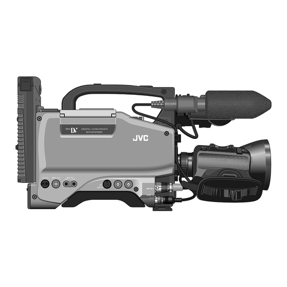
DV CAMCORDER
GY-DV500
The illustration shows the GY-DV500 DV Camcorder with the optional lens viewfinder attached.
Thank you for purchasing this JVC product. Before operating
this unit, please read the instructions carefully to ensure the
best possible performance.
For Customer Use :
Enter below the Serial No. which is located on the body.
Retain this information for future reference.
Model No. GY-DV500
Serial No.
INTRODUCTION
CONTROLS,
INDICATORS AND
CONNECTORS
BASIC SYSTEM
CONNECTIONS AND
ADJUSTMENTS
POWER SUPPLY
PREPARATIONS
SETTING AND
ADJUSTMENTS
BEFORE SHOOTING
SHOOTING
OPERATION
PLAYBACK MODE
INSTRUCTIONS
TIME CODE
OPERATION
S.S.F. (Super Scene
Finder)
yyy
USING EXTERNAL
COMPONENTS
yyy
SETUP MENU
FEATURES OF THE
CAMERA SECTION
OTHERS
This instructions attached to service
manual is different from that which is
provided the GY-DV500.
This instruction manual is made from 100% recycled paper.
SC96874 : U-ver.
SC96875 : E-ver.
Advertisement
Table of Contents

Related Manuals for JVC GY-DV500E - Pal Professional Dv Camcorder


Summary of Contents for JVC GY-DV500E - Pal Professional Dv Camcorder
- Page 1 In this case, let the tape run as the indicator will turn off after the tape has run for a while. Thank you for purchasing this JVC product. Before operating This instructions attached to service Note 3) Use the cleaning tape in the room temperature (10˚C to 35˚C).
-
Page 2: Safety Precautions
15. Never push objects of any kind into this appliance through cabinet slots as they may touch dangerous voltage points CHANGES OR MODIFICATIONS NOT APPROVED BY JVC or short out parts that could result in a fire or electric shock. Never spill liquid of any kind on the appliance. -
Page 3: Table Of Contents
Other use may infringe on the rights of copyright holders. Camera Settings ............42 Characteristic CCD Phenomena ........ 9 ● JVC cannot assume liabilities that may derive from the units and those recorded on this unit may appear Viewfinder Adjustment ..........43 impossibility of normal recording or playback of video or disturbed. -
Page 4: Introduction
Do not exceed 15 V DC in any case, or the OFF the setup level, please consult the person in charge of unit could be damaged. professional video equipment at your nearest JVC-authorized 12. SETUP MENU ● Allowable ambient temperature and humidity service agent. -
Page 5: Routine And Periodical Maintenance
As the replacement, adjustment and servicing of parts require advanced skill and equipment, please consult the person in charge of professional video equipment at your nearest JVC-authorized service agent. To display the remaining battery power accurately, set the VCR Setup Menu item No. -
Page 6: Controls, Indicators And Connectors
2. CONTROLS, INDICATORS AND CONNECTORS 2. CONTROLS, INDICATORS AND CONNECTORS 2-1 Front Section 2-1 Front Section (Cont’d) ACCU-FOCUS: [LENS] Lens control connector • When this switch is set to "ACCU FOCUS" in the lower Connect 12-pin lens control cable from lens. position, the lens iris will be forced to open for Pin No. -
Page 7: Right Side Section
2. CONTROLS, INDICATORS AND CONNECTORS 2. CONTROLS, INDICATORS AND CONNECTORS 2-2 Right Side Section 2-2 Right Side Section [Camera Setting Section] [Camera Setting Section] [AUTO IRIS] Auto iris level switch [WHT.BAL] White balance switch This switch selects the automatic iris adjustment Three white balance modes are selectable with this switch. - Page 8 For servicing When replacing the Lithium Battery, see page 41 “Setting the Date and ← Time” and then set the date and time as described therein. 2. CONTROLS, INDICATORS AND CONNECTORS 2. CONTROLS, INDICATORS AND CONNECTORS 2-2 Right Side Section (Cont'd) 2-2 Right Side Section (Cont'd) [Audio Setting Section] [VCR Setup Block]...
- Page 9 2. CONTROLS, INDICATORS AND CONNECTORS 2. CONTROLS, INDICATORS AND CONNECTORS 2-2 Right Side Section (Cont'd) 2-2 Right Side Section (Cont'd) [VCR Display Section] Warning indicators Tape transport direction indicators [AUTO OFF] indicator One of the indicators lights according to the REV FWD Lights when a non-recoverable error (e.g.
-
Page 10: Left Side Section
Output connector for audio signals. set to 3 or 30 minutes with the VCR Setup Menu item No. For details, please consult your JVC dealer. • When the CONTINUE button (6 on page 15) is pressed • Outputs the input audio signal in the record and stop 307 LONG PAUSE TIME. -
Page 11: Rear Section
It blinks during the transition to the record mode. nearest JVC-authorized service agent. • Use the VCR Setup Menu item No. 082 BACK TALLY MODE to select whether or not the lamp should light and the lighting pattern. -
Page 12: Counter Display Contents
2. CONTROLS, INDICATORS AND CONNECTORS 2. CONTROLS, INDICATORS AND CONNECTORS 2-6 Counter Display Contents 2-6 Counter Display Contents The counter display shows the following 4 types of information. The counter display shows the following 4 types of information. OPERATE/WARNING OPERATE/WARNING LIGHT LIGHT Tape counter display... -
Page 13: Lens (Optional)
2. CONTROLS, INDICATORS AND CONNECTORS 2. CONTROLS, INDICATORS AND CONNECTORS 2-7 Lens (optional) 2-8 1.5-Inch Viewfinder (optional) [S14 x 7.3B12] IRIS mode switch [VF-P115B] Stopper screw A: Activates the auto iris feature. This screw prevents the viewfinder from coming off the M: Allows manual iris control. -
Page 14: Indications In Viewfinder
2. CONTROLS, INDICATORS AND CONNECTORS 2. CONTROLS, INDICATORS AND CONNECTORS 2-9 Indications in Viewfinder 2-9 Indications in Viewfinder (Cont'd) WARNING LED INDICATORS INSIDE THE VIEWFINDER ACCU - FOCUS ACCU - FOCUS SCENE F I L E WH I TE BA L F I L TER 3 . - Page 15 2. CONTROLS, INDICATORS AND CONNECTORS 2. CONTROLS, INDICATORS AND CONNECTORS 2. CONTROLS, INDICATORS AND CONNECTORS 2-9 Indications in Viewfinder (Cont'd) 2-9 Indications in Viewfinder (Cont'd) ● Status 1 Alarm Message Display In addition to the information on the Status 0 screen, this screen displays audio indicators and information on remaining tape, ACCU - FOCUS voltage and lens F-number.
-
Page 16: Basic System Connections And Adjustments Basic System
For servicing → See the service manual page 1-16 “1.11.7 Tripod base”. 3. BASIC SYSTEM CONNECTIONS AND ADJUSTMENTS 2. CONTROLS, INDICATORS AND CONNECTORS 2-9 Indications in Viewfinder (Cont'd) 3-1 Basic System For information on connection with the individual attachments, refer to the page explaining the respective connection methods. Safety Zone Three types of safety zone items can be displayed in the viewfinder. -
Page 17: Attaching The Zoom Lens (Optional)
3. BASIC SYSTEM CONNECTIONS AND ADJUSTMENTS 3. BASIC SYSTEM CONNECTIONS AND ADJUSTMENTS 3-2 Attaching the Zoom Lens (optional) 3-4 Attaching the Microphone (provided) Provided Microphone Connecting the provided microphone to the viewfinder. Loosen the mount ring. The provided microphone is a phantom microphone. 1.3. -
Page 18: Attaching The Tripod Base (Provided)
For servicing → See the service manual page 1-16 “1.11.7 Tripod base”. 3. BASIC SYSTEM CONNECTIONS AND ADJUSTMENTS 3. BASIC SYSTEM CONNECTIONS AND ADJUSTMENTS 3-6 Attaching the Tripod Base (provided) 3-7 Inserting and Replacing Backup Lithium Batteries The GY-DV500 uses a lithium battery for backup of the time code data. Install the provided lithium battery before actually using the Use the provided tripod base to place the camera on a tripod. -
Page 19: Power Supply
4-1 AC Operation Attaching a Flat Shape Type Battery Pack Use the JVC AA-P250 AC power adapter (max. rated output 12.5 V DC, 3.5 A) as the AC power supply. Open the battery case cover while pushing the lock release lever. -
Page 20: Using An Anton-Bauer Battery Pack
4. POWER SUPPLY 4. POWER SUPPLY 4-2 Battery Pack Operation (Cont'd) 4-2 Battery Pack Operation (Cont'd) REMAINING BATTERY POWER DISPLAY Using an Anton-Bauer Battery Pack WARNING To display the remaining battery power accurately, set the To use an Anton-Bauer battery pack (Propack 13/14, Trimpack 13/14, Magnum 13/14, Compack 13/14 Series), it is necessary to indicator VCR Setup Menu item No. -
Page 21: Preparations
5. PREPARATIONS 5. PREPARATIONS 5-1 Turning the Power ON 5-2 Cassette Loading and Unloading Cassette rear switch EJECT AUTO IRIS FULL AUTO BLACK LOLUX Videocassette BACK L STRETCH NORMAL NORMAL EJECT switch SPOT L COMPRESS STOP PLAY STILL OPERATE/WARNING LIGHT RESET MONITOR FILTER... -
Page 22: Setting The Date And Time
6. SETTING AND ADJUSTMENTS BEFORE SHOOTING 5. PREPARATIONS 5-3 Setting the Date and Time 6-1 Camera Settings The date and time of the built-in clock should be set. During shooting, the date and time data are recorded in the sub-time code area POWER ON on the tape. -
Page 23: Viewfinder Adjustment
6. SETTING AND ADJUSTMENTS BEFORE SHOOTING 6. SETTING AND ADJUSTMENTS BEFORE SHOOTING 6-2 Viewfinder Adjustment 6-4 Back Focus Adjustment Adjust the position and angle of the viewfinder. It is only necessary to perform this when the lens is attached 4. 6. for the first time or when focusing is not correct in both the Diopter adjustment telephoto and wide-angle positions. -
Page 24: White Balance Adjustment
6. SETTING AND ADJUSTMENTS BEFORE SHOOTING 6. SETTING AND ADJUSTMENTS BEFORE SHOOTING 6-5 White Balance Adjustment 6-6 Switch Settings of the VCR Section Since the color of light (color temperature) varies depending on the light source, it is necessary to re-adjust the white balance when the main light source illuminating the subject changes. -
Page 25: Audio Input Signal Selection
6. SETTING AND ADJUSTMENTS BEFORE SHOOTING 6. SETTING AND ADJUSTMENTS BEFORE SHOOTING 6-7 Audio Input Signal Selection 6-8 Recording Level Adjustment CH-1 Audio CH-2 Audio select switch select switch OPERATE/WARNING LIGHT OPERATE/WARNING RESET LIGHT RESET MONITOR AUTO SELECT COUNTER FILTER MONITOR 1 3200k COUNTER... -
Page 26: Monitoring Audio During Recording
7. SHOOTING OPERATION 6. SETTING AND ADJUSTMENTS BEFORE SHOOTING 6-9 Monitoring Audio during Recording 7-1 Basic Recording Operation Set the POWER switch to ON. “DEW” Power is supplied to the unit. CH 1 OVER AUTO OFF DEW Check that the condensation indicator "DEW" does not 40 30 0 dB SERVO... -
Page 27: Vcr Save Mode
7. SHOOTING OPERATION 7. SHOOTING OPERATION 7-1 Basic Recording Operation (Cont'd) 7-2 VCR Save Mode 8. 9. 10. Press the VTR trigger button on the GY-DV500 or lens to When a recordable videocassette is loaded, the GY-DV500 start recording. enters the record-pause mode. However, the record-pause VTR trigger button Once recording has started, the BACK TALLY lamp on the operation condition differs depending on the setting of the VTR... -
Page 28: Checking Recorded Contents In Record-Pause Mode
For servicing → See the service manual page 2-7 “2.4.3 Cleaning”. 8. PLAYBACK MODE 7. SHOOTING OPERATION 7-4 Checking Recorded Contents in Record-Pause Mode 8-1 Playback Procedure (Recording Check Function) The recording check function is only valid in the standby mode (VTR switch set to STBY). -
Page 29: Fast-Forward, Rewind
9. TIME CODE OPERATION 8. PLAYBACK MODE The GY-DV500 records SMPTE-standard time codes for U-ver. or EBU-standard time codes for E-ver. and user's bits. In the play or 8-2 Fast-Forward, Rewind the record mode, the reproduced time codes or user's bits are shown on the counter display. •... -
Page 30: Time Code Presetting Procedure
9. TIME CODE OPERATION 9. TIME CODE OPERATION TIME CODE PRESETTING PROCEDURE (for U-ver.) PRESETTING USER'S BIT DATA Display the time code on the counter display. HOLD button SHIFT button Display user's bit data on the counter display and perform Set the COUNTER switch to "TC". -
Page 31: Reproducing Time Codes
10. S.S.F. (Super Scene Finder) FUNCTION 9. TIME CODE OPERATION 9-4 Reproducing Time Codes 10-1 Explanation of the S.S.F. Function During recording, the SSF function records the time code data at the point of time of a desired recorded scene in the unit's memory. The GY-DV500 incorporates a time code reader. -
Page 32: Super Scene Finder) Function
10. S.S.F. (Super Scene Finder) FUNCTION 10. S.S.F. (Super Scene Finder) FUNCTION 10-2 How to Use the S.S.F. Function 10-3 Deleting S.S.F. Data The S.S.F. data recorded in the unit's memory can be deleted in the record mode and the record-pause mode. This function is only valid in the MARK mode. -
Page 33: Writing S.s.f. Data To Tape
11. USING EXTERNAL COMPONENTS 10. S.S.F. (Super Scene Finder) FUNCTION 10-5 Writing S.S.F. Data to Tape 11-1 Connecting a Video Component with DV Connector S.S.F. data stored in the unitís memory can be written to the Rear section of GY-DV500 beginning of tape. -
Page 34: Connecting A Pc
TTL ⇔ RS-232C converter cable. Or connect the GY-DV500’s DV connector and the DV connector of the non-linear editing controller using a DV cable. U-ver. For compatible non-linear editing controller, consult with your JVC dealer. Item Menu Viewfinder display... -
Page 35: Displaying And Setting Vcr Setup Menus
12. SETUP MENU 12. SETUP MENU 12-1 VCR Setup Menu (Cont'd) 12-1 VCR Setup Menu (Cont'd) VCR SETUP MENU CONTENTS DISPLAYING AND SETTING VCR SETUP MENUS Setting Item Factory Value Group Contents Setting CH-1 AUDIO CH-2 Upper row: Viewfinder display TC GENERATOR LEVEL CH-1... -
Page 36: Camera Menu Screen Flow
12. SETUP MENU 12. SETUP MENU 12-1 VCR Setup Menu (Cont'd) 12-2 Camera Menu Screen Flow Camera Menu Screen Flow As illustrated below, the Camera Menu is a menu screen comprising several layers. The first layer of the CAMERA MENU screen is Setting Item for choosing and setting the menus required in accordance with functions or purposes. -
Page 37: How To Select From The Camera Menu
12. SETUP MENU 12. SETUP MENU 12-3 How to Select from the Camera Menu 12-4 VF Display Screen Press the STATUS button for 1 second to display the Item Function, Operation Variation Range Initial Setting CAMERA MENU screen in the viewfinder. F NO. -
Page 38: Operation Screen
12. SETUP MENU 12. SETUP MENU 12-5 OPERATION Screen 12-6 PROCESS Screen Item Function, Operation Variation Range Initial Setting Item Function, Operation Variation Range Initial Setting The SHUTTER button on the right side section is used to select STEP for STEP STEP MASTER... -
Page 39: Advanced Process Screen
12. SETUP MENU 12. SETUP MENU 12-7 ADVANCED PROCESS Screen 12-9 FILE MANAGE Screen The unit has three files that can be used for storing camera menus. The FILE MANAGE screen is for performing the operations for Item Function, Operation Variation Range Initial Setting saving the set CAMERA MENU. -
Page 40: Setup Screen
12. SETUP MENU 12. SETUP MENU 12-10 SETUP Screen 12-11 Resetting of Camera Menu Setting Values Using the FILE MANAGE screen, the CAMERA MENU settings can be reset to the initial setting values. On the FILE MANAGE Item Function, Operation Variation Range Initial Setting screen, select the file of the CAMERA MENU to be reset, and then perform the resetting operation. -
Page 41: Features Of The Camera Section
13. FEATURES OF THE CAMERA SECTION 13. FEATURES OF THE CAMERA SECTION 13-1 Full-Time Auto White Balance (FAW) 13-2 IRIS (Brightness) Adjustment The FAW function adjusts the white balance ADJUSTMENT OF LENS IRIS - - - OPERAT I ON - - - The lens iris can be adjusted using any of the value automatically as the lighting condition SCENE F I L E A... -
Page 42: Shooting The Screen Image On A Computer Monitor
13. FEATURES OF THE CAMERA SECTION 13. FEATURES OF THE CAMERA SECTION 13-3 Shooting the Screen Image on a Computer Monitor 13-4 Gain (Sensitivity) Adjustment Outline The gain should be switched when the brightness is insufficient due to poor lighting conditions. The following operation allows the alignment of the shutter GAIN SWITCHING speed of the camera with the variable scanning rate of a... -
Page 43: Switch Setup According To Illumination And Subject
13. FEATURES OF THE CAMERA SECTION 13. FEATURES OF THE CAMERA SECTION 13-5 Switch Setup According to Illumination and Subject 13-6 How to Use Skin Detail The contour emphasis in the skin color areas of the video signal can be controlled and made to appear gentle and smooth. Various switch settings are performed to accommodate the conditions of the illumination and the subject when shooting. -
Page 44: Others
Status 0 and Status 1 screen in the viewfinder. In other cases, please consult the person in charge of professional video equipment at your nearest JVC-authorized service agent. Lights in case of video head clogging. Operation : Continues. -
Page 45: Warnings In Viewfinder
14. OTHERS 14. OTHERS 14-1 Troubleshooting (Cont'd) 14-1 Troubleshooting (Cont'd) Alarm Indications (Cont'd) WARNINGS IN VIEWFINDER Depending on the alarm conditions, the warning indicators in the LCD display, the WARNING indicator, the TALLY lamp, alarm Viewfinder Warning Lamps Function Failures tones and the viewfinder appear as shown in the following table. -
Page 46: Troubles With Error Code Outputs
GY-DV500. Please POWER switch to ON again after a few minutes. consult the person in charge of professional video equipment at your nearest JVC-authorized service agent. -
Page 47: Troubles Without Error Code Outputs
14. OTHERS 14. OTHERS 14-1 Troubleshooting (Cont'd) 14-2 Hour Meter Display TROUBLES WITHOUT ERROR CODE OUTPUTS The unit can display the accumulated running time of the head drum as hour meter data on the counter display. The hour meter can be displayed by selecting HM (HOUR METER) on the VCR Setup Menu. -
Page 48: Specifications
14. OTHERS 14. OTHERS 14-3 Specifications 14-3 Specifications (Cont'd) CAMERA SECTION INPUT/OUTPUT SIGNALS OPTIONAL ACCESSORIES Image pickup devices:1/2-inch interline CCD x 3 Video signal output : 1 V (p-p), 75 ohms (BNC) Color separation optical system: unbalanced composite output. Viewfinder : VF-P115B, VF-P116 F1.4 3-color separation prism YC output...
Need help?
Do you have a question about the GY-DV500E - Pal Professional Dv Camcorder and is the answer not in the manual?
Questions and answers