Table of Contents
Advertisement
Quick Links
Download this manual
See also:
Instruction Manual
Advertisement
Table of Contents

Related Manuals for JVC GY-DV500U


Summary of Contents for JVC GY-DV500U
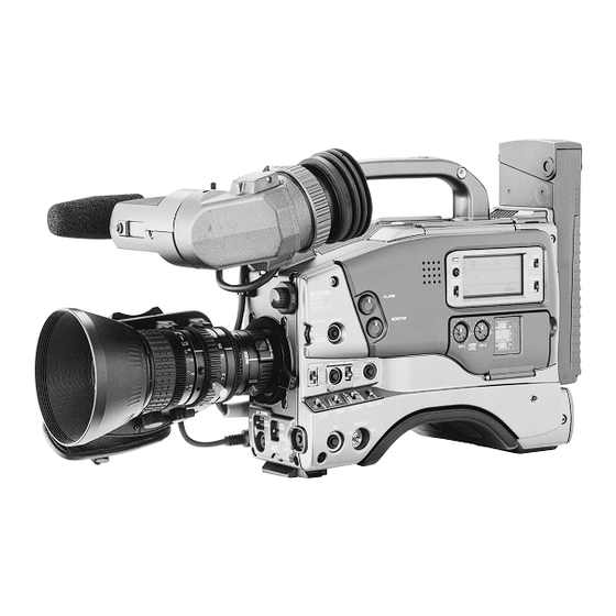
- Page 1 SERVICE MANUAL DV CAMCORDER GY-DV500U/GY-DV500E The photo shows the GY-DV500 DV camcorder with an optional lens and viewfinder. No. 60125 November 1999 COPYRIGHT © 1999 VICTOR COMPANY OF JAPAN, LTD. 100% recycled paper...
-
Page 2: Table Of Contents
2.11 TORQUE ADJUSTMENTS ............ 2-31 • AUDIO/LCD CIRCUIT BOARD 2.12 COMPATIBILITY ADJUSTMENT ........... 2-32 (FOR SERIAL No. 0732 AND AFTER OF GY-DV500U, 0840 AND AFTER OF GY-500E) ................4-32-2 SECTION 3 ELECTRICAL ADJUSTMENTS 4.22 REG(REGulater) SCHEMATIC DIAGRAM 3 3 ..... 4-34 3.1 FLOWCHART OF ELECTRICAL ADJUSTMENTS .... - Page 3 4.34 PR & MDA CIRCUIT BOARD ..........4-54 SECTION 7 PACKING 4.35 ROM, CONN. SCHEMATIC DIAGRAM 0 3 / 0 4 ....4-55 7.1 PACKING ASSEMBLY M 7 ............7-1 4.36 DCDC SCHEMATIC DIAGRAM 0 2 ........4-56 7.2 FACTORY SETTING OF SWITCH AND VR ....... 7-2 4.37 DCDC, ROM, CONN.
-
Page 4: Important Safety Precautions
Important Safety Precautions Prior to shipment from the factory, JVC products are strictly inspected to conform with the recognized product safety and electrical codes of the countries in which they are to be sold. However, in order to maintain such compliance, it is equally important to implement the following precautions when a set is being serviced. - Page 5 Safety Check after Servicing Examine the area surrounding the repaired location for damage or deterioration. Observe that screws, parts and wires have been returned to original positions, Afterwards, perform the following tests and confirm the specified values in order to verify compli- ance with safety standards.
-
Page 6: Section 1 Service Cautions And Disassembly
SECTION 1 SERVICE CAUTIONS AND DISASSEMBLY RESETTING THE POWER CIRCUIT PROTECTION 1.2.2 Opening the Right Side Cover BREAKER (1) Loosen the 4 screws This unit employs a power circuit protection breaker in place of a fuse to disconnect from the main power and to thus protect the internal circuitry from damage caused by any current over- load. -
Page 7: Layouts Of The Major Boards
LAYOUTS OF THE MAJOR BOARDS On the side of the left-hand side cover On the side of the bottom cover 4 2 CONNECT 0 3 ROM 1 0 DV MAIN 1 6 CAM2 3 7 SENS2 4 0 XLR 3 9 AU JUNK 4 3 EAR.J 4 1 PWR JUNC 3 8 REMOTE... -
Page 8: Removing The Optical Block Assembly And The Optical Filter Assembly
Å REMOVING THE OPTICAL BLOCK ASSEMBLY AND (5) Loosen the 2 screws and remove the connector THE OPTICAL FILTER ASSEMBLY (6) Remove the optical filter assembly in the direction of the arrow. (1) Remove the right side cover (see section 1.2.2). (2) Remove the screw retaining the ROM board. -
Page 9: Removing Major Boards From The Camera
(9) Remove the 4 screws and separate the optical block as- REMOVING MAJOR BOARDS FROM THE sembly from the front panel. CAMERA 1.5.1 Removing the CP and TG Boards. (1) Remove the right side cover (see section 1.2.2). (2) Remove the 4 screws retaining the front panel (see section 1.4.3). - Page 10 1.5.2 Removing the CAM1 Board 1.5.3 Removing the SW Boards (1) Remove the left side cover (section 1.2.1). (1) Open the right side cover (see section 1.2.2). (2) Remove the 6 screws (2) The JOG, SWRU, SWRM, SWPW and SWRB boards are (3) The DV MAIN board on the VCR side and the CAM2 board attached on the right side cover.
-
Page 11: Removing The Major Boards From The Vcr
REMOVING THE MAJOR BOARDS FROM THE VCR 1.6.1 Removing the VIDEO/SYSCON Board and Audio/ LCD Board (1) Open the right side cover (see section 1.2.2). The VIDEO/SYSCON board is clamped to the right side cover. (2) Remove the 2 screws . - Page 12 (4) After removing the DV MAIN board, leave it standing up by (3) Unplug the power cable that supplies power from the bat- Ç fitting it into the notches on the unit frame, as shown in the tery case to the main unit, from the connector figure.
-
Page 13: Disassembly Of The Vcr Unit
DISASSEMBLY OF THE VCR UNIT 1.7.2 Disassembling the Rear Part of the Unit (1) Remove the 2 screws and remove the rear side stay. The mechanism unit incorporated in the unit can be disassem- bled as described below. Note that the following description deals only with the method of removing the mechanism unit from the VCR unit. - Page 14 (4) Insulators (blue) are attached to the retaining screws. Be sure to attach the insulators when re-assembling the side stays. (5) The side stays to both sides are attached in the same way. Remove the 2 screws and remove the side stays. Fig.
-
Page 15: Tape Ejection In Case Of Emergency
TAPE EJECTION IN CASE OF EMERGENCY (3) Apply 3 V DC to the electrodes at the top of the loading motor (red wire to + pole, brown wire to - pole) to unload When the cassette tape cannot be ejected normally, take it out the tape. - Page 16 1.8.3 Manual Tape Ejection If the loading motor cannot be run by the procedure outlined in section 1.8.2, the mechanism may be defective. When the load- ing motor is defective, remove the tape as described below. (1) Remove the mechanism unit from the main unit. See sec- tion 1.6.2 for the removal method.
-
Page 17: Caution For Replacing The Dv Main Board And Video Syscon Board
CAUTION FOR REPLACING THE DV MAIN BOARD [B] Load EEPROM Internal Data AND VIDEO SYSCON BOARD The EEPROM provided with the new board for replacement contains no data, while the EEPROM originally provided with When the DV MAIN board or VIDEO SYSCON board has been the VCR unit contains the IEEE1394 ID data as well as all adjust- replaced for servicing, be sure to enforce the following items. -
Page 18: Functions Of Internal Switches
1.10 FUNCTIONS OF INTERNAL SWITCHES 1.10.1 DIP Switch S901 on ROM Board Symbol Name Function Shipment Adjustment mode Adjustment mode ON/OFF Check mode Check mode ON/OFF Not used Character mixing TEST OUT character display ON/OFF S901 Not used Color matrix adjustment Color matrix adjustment mode ON/OFF Setup (NTSC model only) ON (0% setup)/ OFF (7.5% setup) -
Page 19: Modes Required In Servicing
(3) Character mixing (S901-4) 1.11 MODES REQUIRED IN SERVICING Set S901-4 to ON to superimpose the same characters as 1.11.1 Camera Service Menu those displayed on the viewfinder-screen in the output sig- The CAMERA SERVICE MENU can be displayed on the view- nal from the TEST OUT terminal. - Page 20 ERROR DETECT START 1.11.2 System Reset When this item is selected and the SHUTTER dial is pushed, While pushing the [SHUTTER] dial, press the [POWER] switch the white blemish detection for correcting CCD white blemish to ON. This resets the system and initializes the menu set items starts automatically.
-
Page 21: Changing The Color Matrix Setting
1.11.6 EEPROM in Camera 1.12 CHANGING THE COLOR MATRIX SETTING IC905 on the CAM1 board is an electrically erasable/rewritable NOTE EEPROM. It stores the following data. The color reproduction properties of the color-matrix circuit built into the DSP can be re-set by varying the values of 9 Camera adjustment data set in the adjustment mode. - Page 22 (6) Set DIP switch S901-6 on the ROM board to OFF. The color- 1.12.2 Details of Setting Items matrix setting menu is canceled and the normal screen ap- As described above, the color matrix setting consists of varying pears again. 12 items using 9 parameters.
-
Page 23: Service Menu
1.13 SERVICE MENU 1.13.1 Operation Method When the [MENU] button is pressed, the setup menu appears on the viewfinder screen to allow the user to perform setups. (For the contents of the setup menu, refer to page 66 of the instruction manual). Then, with the setup menu displayed, press the [MENU] button while holding down the [LOG] button to display the service menu. - Page 24 1.13.3 Contents of Service Menu Group Item Settings Counter Display Factory Default Description 002: OPERATION LOCK Operation lock setting. SERVO/ R SL SYSTEM 050: REMOTE SELECT LOCAL LOCAL User setup menu (Refer to page 68 of IEEE1394 the instruction manual.) RS232C 080: BATTERY SHUTDOWN V 10.5 –...
- Page 25 Group Item Settings Counter Display Factory Default Description 700: DIP SWITCH-0 Operate LED display switching DIP SW OFF: Blinks in amber when the cassette cover is opened. ON: Extinguished when the cassette cover is opened. 701: DIP SWITCH-1 OFF: Other operations than ejection are inhibited when the cassette cover is opened.
- Page 26 1.13.6 ERROR HISTORY This screen allows the history of the 4 most recent errors to be checked. Error code ( E R R O R H I S T O R Y ) Latest warning Error message 1 : E R R 7 1 0 1 C A P M O T O R F A I L U R E...
-
Page 27: Alarm Detection Methods
1.13.8 OTHERS This screen allows the setup menu to be saved temporarily, loaded or initialized. To execute an item, switch it from “OFF” (displayed as “00”) to “ON” (displayed as “01”) with the [SELECT] button, then press the [DATA SET] button (excluding hour meter). As switching an item “ON” switches other items automatically “OFF”, it is not possible to execute more than one item simultaneously. -
Page 28: Battery Power Detection Methods
1.15 BATTERY POWER DETECTION METHODS 1.16 WARNING CODES The battery voltage is detected to display the remaining power If a problem occurs during operation, the unit diagnoses the on the LCD. Since the detection voltage is variable depending cause by itself, provides a warning through the “warning LED” on the 12 V/13.2 V/14.4 V battery types, correct settings should and “buzzer”, and displays the diagnosis results in the counter be made with the setup menu. - Page 29 3300 UNLOADING INCOMPLETE 5607 TU/SUP REEL STOPPED DUE TO A CUT TAPE •VCR operation : After the first unloading error, the •VCR operation : The AUTO OFF mode is initiated. cassette is loaded temporarily, then •Cause : Tape is cut due to abnormal tension unloading is retried.
- Page 30 7202 SUP TAPE SLACK DURING CAPSTAN DRIVE •VCR operation : The AUTO OFF mode is initiated. •Cause : The timing belt is cut or one of the reel control parts in the mechanism is malfunctioning. •Detection method : When the SUP reel FG has not been detected (at pin 60 of IC401) during 5 rotations of the capstan in the cap- stan driving mode.
-
Page 31: Analysis Of Block Noise (Symptoms: Poor Video, Abscnce Of Audio)
1.17 ANALYSIS OF BLOCK NOISE (SYMPTOMS: POOR VIDEO, ABSCNCE OF AUDIO) 1.17.1 Analysis Flow Chart In case of trouble, perform troubleshooting using the following flow chart. Start Play cleaning tape. Dirt deposited on the head. Play the recorded tape to measure error rate. Is the error rate less than 500 Played tape defect. - Page 32 1.17.2 RF Envelope Check Symptom Observed RF envelope Audio, etc. Possible Causes on Monitor Screen Block noise on left SUP dropout • No audio output. • Supply guide roller adjustment • Intermittent audio. failure. • Dirt on supply side of drum. Block noise on right TU dropout •...
-
Page 33: Berore Adjustments
SECTION 2 MECHANICAL ADJUSTMENTS BERORE ADJUSTMENTS 2.1.1 Precautions 2.1.2 Measuring instruments required for adjustments 1) Be sure to apply a screw securing torque when attaching a Condition Instrument part. Oscilloscope Calibrated instrument with measuring The securing torque should be 0.04 N-m (0.4 kgf-cm) unless bandwidth of 100 MHz or more. -
Page 34: Basics Of Mechanism Disassambly/Assembly
BASICS OF MECHANISM DISASSAMBLY/ASSEMBLY 2.2.1 Assembly mode The disassembly and assembly of the mechanism can be done SEMBLY mode, apply 3 V DC to the electrodes at the top of the in the ASSEMBLY mode (see Table 2-2-1). loading motor shown in Fig. 2-2-1. The ASSEMBLY mode is set The ASSEMBLY mode is provided in the intermediate position when the markings (red) on two gear teeth of the rotary en- between C-IN and S.FF. - Page 35 2.2.2 Mechanism modes The mechanism has 6 modes as shown in Table 2-3-1. The current mode can be confirmed by observing the markings on the sub-cam gear and the 8 mark on the main deck at the back side of mechanism assembly. See Figs. 2-2-2 to -7. 1.
-
Page 36: Mechanism Timin Chart
MECHANISM TIMIN CHART See following table (Table 2-3-1). MODE ASSEMBLY LOADING END C-IN S. FF PLAY STOP FF/REW PARTS ROTARY ENCORDER ROTARY ENCODER 33.33 166.66 193.33 226.66 273.33 306.66 MAIN CAM GEAR SUB CAM GEAR POLE BASE S/REV PLAY CTL PLATE FF/REW ON 1 MAIN BRAKET(SUP) -
Page 37: Maintenance And Inspection Of Major Parts
2.4 MAINTENANCE AND INSPECTION OF MAJOR PARTS Periodical inspection and maintenance are requisite to maintain the product will not only reduce considerably but other the initial performance and reliability of the product. Table 2-4-1 unfavorable influences may produce. (Maintenance & Inspection List) has been compiled assuming Rubber parts may deform or degrade after long period of stor- standard operating conditions, and the specifications in the ta- age even if they are not used in this period. - Page 38 2.4.2 Maintenance and insoection list 1) The 6000 H maintenance consists of a replacement of the entire mechanism assembly. 2) When mounting the capstan motor on the main deck, control of the verticality is required. Therefore, when the capstan motor reaches the end of its service life, the entire mechanism assembly should be replaced.
- Page 39 2.4.3 Cleaning 2.4.4 Oiling and Greasing The tape transport system should be cleaned periodically. Be Table 2-4-2 shows the oil and greases used with the set. sure to clean the tape transport system upon receipt of a set for servicing, etc. To clean use a good quality fine-textured cloth Classification Name Part No.
-
Page 40: Periodical Maintenance
PERIODICAL MAINTENANCE Perform maintenance at the correct times in accordance with the maintenance table. Fig. 2-5-1 shows the flow chart of periodical maintenance procedures at different operating hours. 1000-hour maintenance 2000-hour maintenance 6000-hour maintenance Start Start Start Replaced parts Replaced parts Replaced parts Mechanism assembly ⁄... -
Page 41: Disassembly/Assembly Of Mechanism Assembly
DISASSEMBLY/ASSEMBLY OF MECHANISM ASSEMBLY 2.6.2 Screws and Washers Used in Mechanism Assembly Disassembly/Assembly 2.6.1 Assembly/Disassembly The following table shows the mechanism assembly/disassem- Table 2-6-1 shows the symbols, designs, part numbers and colors bly procedures. of the screws and washers used with the Mechanism assem- : Names of the disassembled/assembled parts. - Page 42 2.6.3 Mechanism Assembly Disassembly Procedure Table Part Name Item Points Remark Å Cassette housing assembly 2 (S1), (L1) to (L5) Drum assembly 3 (S2) Motor bracket assembly 4 (S2) Middle catcher assembly 3 (S2) Reel cover assembly (S2), 2 (L6) Pinch roller arm assembly (W1), (L7) Sub-brake assembly...
- Page 43 ∼ Fig. 2-6-1 2.6.4 Mechanism disassembly/assembly procedure chart <How to read the chart> ⋅ The following chart shows the disassembly/assembly procedures by dividing them into blocks A to I. ⋅ To remove the tension arm sub-assembly which is located in block D; start disassembly from block A. The tension arm sub-assembly can be removed as the fourth operation after the removals of the cassette housing assembly (block A) →...
-
Page 44: Replacement Of Major Parts
Item Reference picture/drawing Procedure REPLACEMENT OF MAJOR PARTS ⋅ Make sure that the mechanism is in the ASSEMBLY mode before proceeding to disassembly or assembly. (See section 2.1, “Assembly Mode”.) ⋅ Screws must always be tightened using a torque screwdriver and at the specified torque. Å... - Page 45 Item Reference picture/drawing Procedure Pinch roller arm assembly <Removal> 1) Remove the washer (W1) and pull out the assem- ( W1 ) bly. <Attaching> Å 1) Fit the pinch roller arm assembly into the boss (L7) of the charge arm assembly. 2) Attach the washer (W1).
- Page 46 Item Reference picture/drawing Procedure Middle catcher assembly <Removal> 1) Remove the 3 screws (S2) and remove the assem- bly. ( S2 ) 11 ( S2 ) ( S2 ) <Attaching> 1) Reverse the removal procedure. Fig. 2-7-5 Reel cover assembly <Removal>...
- Page 47 Item Reference picture/drawing Procedure Swing arm assembly <Removal> 1) Pull the assembly upward. <Attaching> 1) Reverse the removal procedure. Fig. 2-7-7 2-15 2-16...
- Page 48 Item Reference picture/drawing Procedure Band arm plate assembly, Tension arm sub-assembly <Removal> 1) Remove the washer (W2). ( S3 ) 2) Remove the screw (S3). ( W2 ) 3) Remove the spring (P2). 4) Remove the band arm plate assembly and tension arm sub-assembly.
- Page 49 Item Reference picture/drawing Procedure <Tension arm sub-assembly position adjustment> 1) Without loading a tape, set the mechanism mode to PLAY mode. To switch the mode, rotate worm wheel 2 while the motor bracket assembly is disengaged (see 2.2, “Mechanism Modes”). 2) Rotate the tension arm slightly clockwise to elimi- nate production of rattle with the band arm plate.
- Page 50 Item Reference picture/drawing Procedure Sub-deck assembly <Removal> 1) Remove the 4 screws (S2) and pull out the assem- ( S2 ) bly. The boss should fit into the hole. ( S2 ) ( S2 ) ( S2 ) <Attaching> 1) While sliding the control plate toward the left, at- tach the sub-deck assembly.
- Page 51 Item Reference picture/drawing Procedure Reel base (SUP) assembly, Reel base (TU) assembly, <Removal> & Control plate, Prism 1) Pull up each assembly to remove it. The control plate can be removed by sliding it toward the left as shown by the arrow. 2) Remove the screw (S2) to remove the prism.
- Page 52 Item Reference picture/drawing Procedure <Removal> Base plate assembly 1) Remove the screw (S2) and take out the assem- bly. ( S2 ) <Attaching> 1) Attach the assembly to the boss (L14) as if insert- ing, then clamp with the screw. ( L14 ) Fig.
- Page 53 Item Reference picture/drawing Procedure fi fl ‡ Reel drive pulley assembly, Push plate, Clutch lock gear (1), <Removal> ° 1) Remove the washer (W1) and take out the assem- Clutch lock gear (2) bly. ( W1 ) <Attaching> ( W3 ) ( W1 ) 1) Reverse the removal procedure.
- Page 54 Item Reference picture/drawing Procedure · ‚ Tension control arm assembly, Brake control arm assembly, <Removal> ¡ 1) The brake control assembly can be removed after Charge arm assembly removing the washer (W1). ( L16 ) ( W1 ) <Attaching> 1) Align the phases of the main cam and sub cam , then attach by reversing the removal procedure.
- Page 55 Item Reference picture/drawing Procedure ™ £ <Removal> Connect gear 2 (SUP), Connect gear 2 (TU) 1) Remove the screw (S2) and take out the gears. ( S2 ) <Attaching> 1) Reverse the removal procedure. The two connect gears 2 are given the same part number. ( S2 ) NOTE ⋅...
- Page 56 Item Reference picture/drawing Procedure ¢ ∞ § Rotary encoder assembly, Main cam , Arm gear 1 assembly, <Removal> ¶ 1) The rotary encoder can be removed by removing Centering arm assembly the 2 screws (S2). 2) The main cam can be removed by removing the ( S2 ) washer (W1).
- Page 57 Item Reference picture/drawing Procedure • ª º <Removal> Sub cam Arm gear 2 assembly, Clutch lock lever assembly 1) Remove the screw (S2) and take out the sub cam . As L19 is engaged at the rear of the main deck assembly while the phase is aligned, deviate the phase in the direction of the arrow before removal.
- Page 58 Item Reference picture/drawing Procedure <Removal> Cleaner assembly 1) Remove the washer (W2) 2) Take out the cleaner assembly. <Attaching> 1) Reverse the removal procedure. 2) Activate the cleaner (loading) and ensure that the cleaner contacts the drum normally. (Make sure that the cleaner rotation sound is heard.) <When an active head cleaner assembly is dis- assembled>...
-
Page 59: Confirmation And Adjustment Of Mechanism Phases
CONFIRMATION AND ADJUSTMENT OF MECHANISM PHASES See Fig. 2-8-1. 22 Worm wheel 2 36 Arm gear 1 assembly See section 2.7.14 See section 2.7.18 34 1 Worm wheel 2 See section 2.7.18 39 Arm gear 2 assembly See section 2.7.19 38 Sub cam See section 2.7.19 35 Main cam... -
Page 60: Mechanism Disassembly/Assembly Sheet
MECHANISM DISASSEMBLY/ASSEMBLY SHEET Screw Management Å Drawing No. Table Application Ref. No. No.1 No.2 No.5 No.8 No.9 Å Cassette housing assembly Drum assembly Reel cover assembly ( S2 ) ( S1 ) ( S2 ) ( S2 ) ( S2 ) ( S1 ) S2 ×... - Page 61 Screw Management ( ) ⁄ ™ £ ¢ • 19 20 21 22 23 24 25 26 27 28 29 30 31 32 33 34 S2 S2 S2 S2 S2 S2 S2 S2 S2 S2 S2 S2 S2 S2 S2 S2 The slit washers cannot be reused once they have been removed.
-
Page 62: Disassembly Procedure List
2.10 DISASSEMBLY PROCEDURE LIST 14(S3) (W2) (S2) (S2) (S2) (S2) (P3) (W1) 6(S2) 9(S2) (S2) 7(S2) 8(S2) (S2) (S2) (S2) (S2) (S2) (S2) (S2) (S2) (S2) 31(S2) (S2) (S2) (S2) (S2) (S2) (W1) (S2) (S2) (W1) (S2) (S2) ADJ. (W1) (P7) (S2) (S2) -
Page 63: Torque Adjustments
2.11 TORQUE ADJUSTMENTS Measuring point ( * ) Measuring Adjustment parts ( - ) Item instruments & Mode Adjustment procedure Adjustment level ( + ) Input signals * Supply side indica SUP backup • Cassette torque Play (1) nsert the cassette torque meter and enter play torque meter tion of cassette... -
Page 64: Compatibility Adjustment
2.12 COMPATIBILITY ADJUSTMENT 2.12.1 Compatibility Adjustment Flow Chart Fig. 2-12-1 shows the flow chart of compatibility adjustment. Start Connect the jig connector. Enter modes PLAY → SEARCH REV → Set the RF envelope adjusted waveform flat. SEARCH FWD → PLAY in this sequence, and ensure that tape is not damaged by wrinkles. - Page 65 Adjustment software As shown in Fig.2-12-2 below, connect the connector cable to CN104 on the DV MAIN board and then connect it to the PC cable. RS-232C port JVC menu Personal computer FS PLL VCO DC PC cable A GND...
- Page 66 TU guide roller MID guide roller 2.12.4 Tape Transport Restriction SUP slant pole The unit uses only the SUP guide roller and TU guide roller to SP guide roller restrict the tape transport. The tape is free (no restriction) from other parts.
- Page 67 Measuring point ( * ) Measuring Adjustment parts ( - ) Item instruments & Mode Adjustment procedure Adjustment level ( + ) Input signals 2.12.5 Compatibility Adjustment Preparation (1) Set up the adjustment software (see section 2.12.3, “Setup”) and execute the program. (2) If it is required to switch the auto tracking func- tion, set [ATF] to “OFF”.
- Page 68 Measuring point ( * ) Measuring Adjustment parts ( - ) Item instruments & Mode Adjustment procedure Adjustment level ( + ) Input signals * ENV OUT Eject →Play (1) Switch the mode from Eject → Play and en- Waveform •...
-
Page 69: Section 3 Electrical Adjustments
SECTION 3 ELECTRICAL ADJUSTMENTS 3.1 FLOWCHART OF ELECTRICAL ADJUSTMENTS CAMERA PART VCR PART AUDIO PART Malsyncronizing Malsyncronizing 3.5.1 SSG Adjustment 3.7.7 Servo Circuit Adjustment 3.7.8 RF Circuit Adjustment Abnormal video level Abnormal audio level 3.7.10 Audio Circuit Adjustment Abnormal color-bar level 3.6.2 Audio Circuitry Adjustment GOOD 3.5.2 Encoder Adjustment... -
Page 70: Functions Required For Adjustments, Setup
3.2 FUNCTIONS REQUIRED FOR ADJUSTMENTS, SETUP 3.2.1 General instruments necessary for adjustment Instrument Condition Instrument Condition Oscilloscope Calibrated instrument with a measuring Frequency counter Instrument calibrated for 8 digits or more. bandwidth of 100 MHz or more. Stability of 0.1 ppm or 1x10 or better is Vectorscope Calibrated instrument... -
Page 71: Standard Setup
3.3 STANDARD SETUP Color video monitor Waveform monitor (WFM) Oscilloscope Vectorscope 75 Ø resistor for termination 75 Ø resistor for termination Filter 1 (3200 K) Test pattern OPERATE/WARNING LIGHT RESET MONITOR 2 m or more SELECT COUNTER FILTER 1 3200k ALARM 2 5600k 3 5600k+ND... - Page 72 3.4.2 Operation Procedure (1) Open the right side cover and set the DIP switch SW901-1 on the ROM board to ON (up). (2) When the cursor on the left of an item is blinking and the adjustment value is lit steadily, rotating the SHUTTER/MENU dial selects the adjustment item.
-
Page 73: Camera Adjustments
Measuring point (*) Measuring Adjustment parts (-) Item instruments & Mode Adjustment procedure Input signals Adjustment level (+) 3.5 CAMERA ADJUSTMENTS 3.5.1 SSG Adjustment * TP101 (CAM2) fh frequency • Frequency Adjustment (1) Open the left side cover. - SHUTTER/MENU adjustment counter menu 1/6... - Page 74 Measuring point (*) Measuring Item instruments & Mode Adjustment parts (-) Adjustment procedure Input signals Adjustment level (+) 3.5.3 Video Black Level Adjustments * TEST OUT DSP IN • Oscilloscope Adjustment (1) Rotate the SHUTTER/MENU dial to select (75 Ø terminated) BLACK (H-rate, 10:1) menu 2/6...
- Page 75 Measuring point (*) Measuring Adjustment parts (-) Item instruments & Mode Adjustment procedure Input signals Adjustment level (+) * TEST OUT AGC IN • Oscilloscope Adjustment (1) Rotate the SHUTTER/MENU dial to select (75 Ø terminated) BLACK (V-rate, 10:1) menu 3/6 MENU 3/6: AGC IN BLACK <G>.
- Page 76 Measuring point (*) Measuring Item instruments & Mode Adjustment parts (-) Adjustment procedure Input signals Adjustment level (+) 3.5.4 Video White Level Adjustments * TP2 (TG,Open the IN GAIN • Oscilloscope Adjustment (1) Rotate the SHUTTER/MENU dial to select left side cover) adjustment (H-rate, 10:1) menu 4/6...
- Page 77 Measuring point (*) Measuring Adjustment parts (-) Item instruments & Mode Adjustment procedure Input signals Adjustment level (+) 3.5.5 Flare Correction Adjustments * TEST OUT Flare adjust- • Oscilloscope Adjustment (1) Rotate the SHUTTER/MENU dial to select (75 Ø terminated) ment (H-rate, 10:1) menu 5/6...
- Page 78 Measuring point (*) Measuring Item instruments & Mode Adjustment parts (-) Adjustment procedure Input signals Adjustment level (+) * TEST OUT ABL adjust- • Oscilloscope Adjustment (1) Rotate the SHUTTER/MENU dial to select (75 Ø terminated) ment (H-rate, 10:1) menu 5/6 MENU 5/6: ABL.
-
Page 79: Vcr Adjustments
3.6 VCR ADJUSTMENTS 3.6.1 Audio Circuitry Adjustments Before adjustments, set the audio switches, menu and potentiometer as follows. LINE MANUAL CH-1 CH-2 AUDIO TC GENERATOR LEVEL CH-1 CH-2 PRESET FREE AUTO REGEN MANUAL AUDIO SELECT CH-1 AUDIO IN CH-2 AUDIO INPUT TALLY CH-1 CH-2... - Page 80 Measuring point (*) Measuring Item instruments & Mode Adjustment parts (-) Adjustment procedure Input signals Adjustment level (+) 3.6.2 Audio Circuitry Adjustments Note : Before proceeding to section “3.5.2 Audio Circuitry Adjustments”, complete “3.6.10 Audio Circuitry Adjustment of DV Unit”. Preparation Before adjustments, set the audio switches, menu and potentiometer as follows:...
- Page 81 Measuring point (*) Measuring Adjustment parts (-) Item instruments & Mode Adjustment procedure Input signals Adjustment level (+) 3.6.3 Video Circuitry Adjustments * TP3[VIDEO/SYSCON] SETUP PULSE • Oscilloscope (1) Play the color bar section of alignment tape - VR2[VIDEO/SYSCON] adjustment (V-rate, 10:1) MC-1 / MC-2.
-
Page 82: Dv500E)
Color TV monitor Oscilloscope (2-trace, 100 MHz or more) * 300 MHz or more recommended. Digital voltmeter Frequency counter (with threshold level adjustment) Tape for use in recording/playback (JVC ME60) Cleaning tape Fig. 3-7-1 Setup for PC Adjustment 3-15 3-14... - Page 83 3.7.4 Installing the Adjustment Software 2. Function description Insert the floppy disk of the adjustment software and run “Setup.exe”. “Professional DV Adjustment” will be created in “Program” under the Start menu. 3.7.5 Operating the Adjustment Software 1. Startup Execute “Professional DV Adjustment”. When the follow- ing screen appears, click <OK>...
- Page 84 [Option] tab ROM file display Shows the file name or “Current VCR data” while a ROM tool reads EEPROM data. Clicking [ROM Monitor] under the [View] tab displays the data contents. 3.7.6 Common Operations for Adjustments Note: Before adjustment, be sure to save the EEPROM Fig.
- Page 85 Measuring point (*) Measuring Adjustment parts (-) Item instruments & Mode Adjustment procedure Input signals Adjustment level (+) 3.7.7 Servo Circuit Adjustment Automatic adjust- PB switching • Alignment tape (1) Click [PB Switching Point (Auto)]. ment point MC-1, color bar (2) Click [OK] to start automatic adjustment.
- Page 86 Measuring point (*) Measuring Item instruments & Mode Adjustment parts (-) Adjustment procedure Input signals Adjustment level (+) 3.7.8 RF Circuit Adjustment * TP REC MON REC current • Internal Color Note: Connect TP to the section indicated [REC (connector cable) adjustment bars (100%) MON] on the jig connector in advance.
- Page 87 Measuring point (*) Measuring Adjustment parts (-) Item instruments & Mode Adjustment procedure Input signals Adjustment level (+) * PC monitor PB EQ • Internal color • REC Notes: • Use a new tape or non-used section of ↓ - 68 h, 69h, 67h, 6Bh, (Error rate) bars (100%) tape in this adjustment.
- Page 88 Measuring point (*) Measuring Item instruments & Mode Adjustment parts (-) Adjustment procedure Input signals Adjustment level (+) 3.7.9 Video Circuit Adjustments * Y OUT D/A Y level • Internal color (1) Click [D/A Y Level]. (75 Ø terminated) adjustment bars (100%) (With PLAY lit (2) Click the [OK] button.
- Page 89 Measuring point (*) Measuring Adjustment parts (-) Item instruments & Mode Adjustment procedure Input signals Adjustment level (+) 3.7.10 Audio Circuit Adjustment (Note) • Perform the audio circuitry adjustments immediately after turning the main unit ON. Be sure to turn the main unit OFF after completing each adjustment item.
- Page 90 3.7.11 Error Rate Monitoring 3.7.12 ROM Tools The error rate-monitoring screen is displayed when the PB EQ This section describes the seven functions of the ROM Tools in is adjusted or the error rate is measured. The screen shows the processing the EEPROM data.
- Page 91 3.7.13 IEEE1394 ID Setting 3.7.14 Active Head Cleaner Adjustment Mode The GY-DV500 stores the ID in the format specified by the When adjusting the installation position of the active head IEEE1394 standard in the EEPROM (IC103 on DV Main board). cleaner, use this mode to force the active head cleaner ON for a After replacing the EEPROM or the DV Main board, it is required certain period.
- Page 92 VICTOR COMPANY OF JAPAN, LIMITED Printed in Japan...
Need help?
Do you have a question about the GY-DV500U and is the answer not in the manual?
Questions and answers