Advertisement
Table of Contents
- 1 Table of Contents
- 2 Safety Information
- 3 Component Identification
- 4 Identification of Components
- 5 Pre-Operation Check
- 6 Starting the Generator
- 7 Using the Generator
- 8 Stopping the Generator
- 9 Maintenance
- 10 Storage
- 11 Troubleshooting
- 12 Specifications
- 13 Wiring Diagram
- 14 Warranty
- Download this manual
Advertisement
Table of Contents

Related Manuals for Kipor KGE2400X


Summary of Contents for Kipor KGE2400X
- Page 3 Thank you for purchasing a Kipor Generator from the Coast Distribution System. This manual covers the operation and preventive maintenance of the KGE2400X generator. All information in this publication is based on the latest product information available at the time of printing.
- Page 4 The portable generator is not meant to be used as a permanent back-up power system for the home. A permanently installed stationary generator is designed to be safely used for this specific purpose. Do not connect this generator directly to the home utility panel. It can only be connected to a manual style transfer switch by a qualified electrician.
-
Page 5: Table Of Contents
CONTENTS 1. Safety information ···········································································································1 2. Identification of components····························································································3 3. Pre-operation check ········································································································5 4. Starting the generator ······································································································8 5. Using the generator ·········································································································9 6. Stopping the generator ··································································································13 7. Maintenance··················································································································14 8. Storage ··························································································································17 9. Troubleshooting·············································································································18 10. Specifications ··············································································································20 11. Wiring diagram·············································································································21 12. - Page 6 This page left intentionally blank.
-
Page 7: Safety Information
1. SAFETY INFORMATION ■ Our generators are designed to give safe and dependable service if operated according to these instructions. ■ Read and understand the owner's manual before operating the generator. Failure to do so could result in personal injury or equipment damage. - Page 8 To ensure safe operation: ■ Keep away from smoking materials, sparks and other sources of combustion when refueling the generator. Always refuel in a well-ventilated location. ■ Gasoline is extremely flammable and explosive under certain conditions. Refuel in a well ventilated area with the engine stopped. ■...
-
Page 9: Identification Of Components
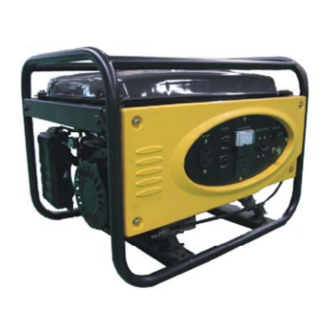
2. COMPONENT IDENTIFICATION 2.1 Generator Components 1. Fuel Gauge 6. Oil Filler Cap 2. Choke 7. Control Panel 3. Fuel Valve 8. Gasoline Tank 4. Air Cleaner 9. Spark Plug 5. Recoil Starter 10. Muffler 2.3 Control Panel... - Page 10 2.3 Serial Number and Bar Code Identification Serial Number and Barcode Location The engine serial number is located on the engine block immediately to the left of the oil drain plug. The generator serial number is located on the aluminum shroud surrounding the alternator. Serial numbers may be required when ordering parts.
-
Page 11: Pre-Operation Check
3. PRE-OPERATION CHECKS Be sure to perform the following checks before starting the generating set. 3.1 Insure the generator is on a level surface. Check for gasoline and oil leaks and correct any problems before proceeding. 3.2 Check engine oil. Take out the oil filler cap and clean the indicator stick with a clean lint free rag. - Page 12 3.3 Check the fuel level Read the gauge or remove the fuel tank cap and visually check the level. Add fuel if level is too low. Tighten the fuel tank cap securely after filling. • Use unleaded 87 octane regular gasoline. Do not use premium or high octane fuels. •...
- Page 13 3.4 Check the air cleaner (1) Unfasten the clips and remove the air filter cover. Remove the air filter element and observe for cleanliness. (2) Clean the air filter element by washing in soap and water or solvent. Squeeze dry and then soak in clean engine oil. Squeeze out all excess oil and reinstall.
-
Page 14: Starting The Generator
4. STARTING THE GENERATOR (1) Disconnect any load from the AC receptacle (2) Set the fuel oil valve to “ON” position. and switch off the AC breaker. (3). Set the choke lever to “CHOKE” position. 4. Set the engine switch to "ON" position. ENGINE SW 5. -
Page 15: Using The Generator
5. USING THE GENERATOR 5.1 In order to keep the generating set in an optimal mechanical and electrical condition please follow these instructions: (1) Secure the grounding terminal of the set to a secure ground. (2) If the generating set is to be connected with more than one load, connect the higher starting current load first. - Page 16 5.3 Load Characteristics Electrical appliances such as fluorescent bulbs and motors will draw very high current while starting and a higher current while running. Use the table below to manage electrical loads. When connecting more than one appliance to the generator, connect the one with the higher current draw first. Let it come to normal operation before connecting the second appliance.
- Page 17 5.4 DC Charge Function The DC receptacle is to be used for charging automotive and marine batteries only. Any other use such as operating DC motors may cause irreparable alternator damage and is prohibited. 1. Connect the charging cable to the DC receptacle of the generator and then to the battery terminals. Use only the charging cable supplied with the generator.
- Page 18 2. Start the generator. The DC receptacle may be used while AC power is in use. The DC receptacle is protected from an overload with a fuse. If the DC circuit is overloaded, the 5 amp fuse will blow and power to the DC receptacle will cease. The red light on the DC panel will illuminate.
-
Page 19: Stopping The Generator
6. STOPPING THE GENERATOR 6.1 Normal Stop a. Turn off all connected loads and disconnect from the generator. Switch off the AC breaker. 6.2 Put the engine switch in the off position and turn the fuel cock to “OFF”. ENGINE SW 6.2 Emergency Shutdown To stop the generator in an emergency, turn the engine switch “OFF”. -
Page 20: Maintenance
The above-mentioned items must be performed with the assistance of a trained Kipor generator technician. ■ Use genuine Kipor parts or the equivalent. The use of replacement parts which are not of equivalent quality may damage the generator and void the warranty. - Page 21 7.1 Change engine oil Oil Filler Cap Oil Drain Plug 1. Open oil filler cap. 2. Loosen the drain screw plug and drain the engine oil. 3. Reassemble the drain screw plug. 4. Refill engine oil to the upper limit level of the oil filler cap. 5.
- Page 22 7.3 Spark plug Remove the spark plug wire from the plug. Remove the spark plug with the wrench provided with the generator Visually inspect the spark plug. Discard it if any portion of the porcelain insulator is chipped or cracked. Remove any carbon buildup with a wire brush.
-
Page 23: Storage
8. STORAGE 1. Open the drain screw on the carburetor and drain all gasoline from the carburetor. Be sure to carefully collect all fuel without spilling and dispose of properly. Drain Screw Drain 2. Remove the filler cap and drain screw plug and drain the engine oil. 3. -
Page 24: Troubleshooting
1) Turn off the fuel valve and loosen the drain screw. 2) Fuel should flow from the drain when the fuel valve is turned on. If the engine still does not start, take the generator to an authorized KIPOR dealer. - Page 25 Appliance does not operate: Is the circuit breaker in the “ON” position Place in the “ON” position Check the electrical appliance or Take the generator to an equipment for any defects. authorized dealer. ■ Replace electrical appliance or equipment Take electrical ■...
-
Page 26: Specifications
10. SPECIFICATIONS Model KG200 Type 4-stroke, OHV Displacement cc Cooling system Forced air Engine Ignition system T.C.I Spark plug BP6ES Fuel tank gal (L) 3.2 (15) Engine oil qt (L) .85 (0.8) Compression ratio 8.5:1 Frequency 60 Hz Voltage Max output 2.4 KW Max current 20 A... -
Page 27: Wiring Diagram
11. WIRING DIAGRAM... -
Page 28: Warranty
13. Warranty Limited Warranty Kipor Power Equipment LENGTH OF WARRANTY Generators are covered by this warranty from the date of original retail purchase for a period of two years for residential use and one year for commercial applications. Units used in rental fleets or as demonstration models will be considered commercial usage.
Need help?
Do you have a question about the KGE2400X and is the answer not in the manual?
Questions and answers