Table of Contents
Advertisement
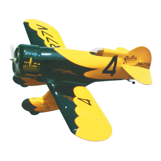
"Graphics and specifications may change without notice".
Specifications
Wingspan-------------------------------------- 70.9 in------------------------------ 180cm.
Wing area------------------------------------- 863.4 sq.in------------------- 55.7 sq.dm.
Approximate flying weight------------------10.6 lbs------------------------------4.8kg.
Length------------------------------------------ 46.6in -----------------------------118.3cm.
Recommended engine size-------------- .1.20 cu.in----------------------- 2-stroke.
Radio System required 4 channels with 6 servos
Flying skill level Intermediate/advanced.
Kit features.
•
Ready-made—minimal assembly & finishing required.
•
Ready-covered covering.
•
Photo-illustrated step-by-step Assembly Manual.
Made in Vietnam.
ASSEMBLY MANUAL
.1.50cu.in------------------------4-stroke.
MS: SEA 82
Advertisement
Table of Contents

Related Manuals for Seagull Models GEEBEE ARTF


Summary of Contents for Seagull Models GEEBEE ARTF
-
Page 1: Specifications
MS: SEA 82 ASSEMBLY MANUAL “Graphics and specifications may change without notice”. Specifications Wingspan-------------------------------------- 70.9 in------------------------------ 180cm. Wing area------------------------------------- 863.4 sq.in------------------- 55.7 sq.dm. Approximate flying weight------------------10.6 lbs------------------------------4.8kg. Length------------------------------------------ 46.6in -----------------------------118.3cm. Recommended engine size-------------- .1.20 cu.in----------------------- 2-stroke. .1.50cu.in------------------------4-stroke. Radio System required 4 channels with 6 servos Flying skill level Intermediate/advanced. -
Page 2: Instruction Manual
GEEBEE. INTRODUCTION. Thank you for choosing the GEEBEE ARTF by SEAGULL MODELS. The GEEBEE was designed with the intermediate/advanced sport scale in mind. It is a semi scale airplane which is easy to fly and quick to assemble. The airframe is conventionally built using balsa, plywood to make it stronger than the average ARTF , yet the design allows the aeroplane to be kept light. -
Page 3: Hinging The Ailerons
www.seagullmodels.com NOTE: 3) Slide the wing panel on the aileron until To avoid scratching your new aero- there is only a slight gap. The hinge is now plane we suggest that you cover your work- centered on the wing panel and aileron. bench with an old towel. -
Page 4: Hinging The Elevator
Instruction Manual GEEBEE. 7) Repeat this process with the other wing HINGING THE ELEVATOR. panel, securely hinging the aileron in place. 8) After both ailerons are securely hinged, Glue the elevator hinges in place using the firmly grasp the wing panel and aileron to same techniques used to hinge the ailerons. -
Page 5: Rudder Control Horn
www.seagullmodels.com CONTRONL HORN CONTRONL HORN M3 M3 SCREW Aluminum Washer Epoxy. Epoxy ALUMINUM WASHER Wing Aluminum Washer M3 LOCK NUT M3 LOCK ALUMINUM WASHER Epoxy. Horizontal Stabilizer. Wing 16mm 16mm Epoxy. Elevator control horn. RUDDER CONTROL HORN. Rudder control horn: ELEVATOR CONTROL HORN. -
Page 6: Engine Mount Installation
Instruction Manual GEEBEE. CONTRONL HORN M3 SCREW ALUMINUM WASHER EPOXY. 4x30mm. Mark and drill 4 holes for engine mount. ALUMINUM WASHER Insert 4 blind nuts to firewall. M3 LOCK NUT Thread locker glue. EPOXY. Rudder Fuselage 16mm 3 x 25mm. Rudder control horn. -
Page 7: Fuel Tank Installation
www.seagullmodels.com 5) With the stopper assembly in place, the weighted pick-up should rest away from the rear of the tank and move freely inside the tank. The top of the vent tube should rest just below the top of the tank. It should not touch the top of the tank. -
Page 8: Mounting The Engine
Instruction Manual GEEBEE. Blow through one of the lines to ensure 5) Bolt the engine to the engine mount using the fuel lines have not become kinked in- the four machine screws. Double check that side the fuel tank compartment. Air should all the screws are tight before proceeding. -
Page 9: Cowling Installation
www.seagullmodels.com COWLING INSTALLATION. 1) Slide the fiberglass cowl over the en- gine and line up the back edge of the cowl with the marks you made on the fuselage then trim and cut. Trim and cut. Because of the size of the cowl, it may be nec- essary to use a needle valve extension for the high speed needle valve. -
Page 10: Installing The Switch
Instruction Manual GEEBEE. 1) Install the rubber grommets and brass collets onto the throttle servo. Test fit the servo into the aileron servo mount. 2) Secure the servos with the screws pro- vided with your radio system. Elevator servo. Rudder servo. Elevator servo. -
Page 11: Installing The Aileron Servos
www.seagullmodels.com Installing the aileron servo in place using the Elevator servo arm. same techniques used to flap servo. Rudder servo arm. Small weight. String. Throttle servo arm. Elevator servo arm. INSTALLING THE AILERON SERVOS. Aileron Servo. Servos. Small weight. Electric wire. Thread. -
Page 12: Wing Assembly
Instruction Manual GEEBEE. Wing Wing Aileron Aileron M2 lock nut. Epoxy. Aileron. Wing. 2) Remove the brace when satisfied with its fit ineach wing half. Coat the dihedral brace with 30 minute epoxy. Next, pour some epoxy Repeat the procedure for the other wing. into the dihedral box in one wing panel. -
Page 13: Installing The Horizontal Stabilizer
www.seagullmodels.com Masking tape. Pen. 3) Peel off the backing from the self adhe- sive covering strip. Apply the strip to the centre section of the wing starting from the bottom trailing edge. Wrap the strip all the way around the wing until it meets the trailing edge again. Trim off any excess strip. -
Page 14: Installing The Vertical Stabilizer
Instruction Manual GEEBEE. Put the vertical stabilizer into the in the top of the horizontal fin. The bottom edge of the stabilizer should also be firmly pushed against the top of the horizontal stabilizer. Vertical Stabilizer. Horizontal 90º Stabilizer. INSTALLING THE VERTICAL STABILIZER. Hinge. - Page 15 www.seagullmodels.com Spring landing gear. INSTALLING THE MAIN GEAR WIRES. 9mm. 11mm. M3 x 30mm 1) Using a modeling knife, remove the covering from over the two main gear mount- Remove the covering. ing slots located in the bottom of the wing. 2) Insert the 90º...
-
Page 16: Wheel Pant Installation
Instruction Manual GEEBEE. Install wooden tray to right position. Trim and cut Screw M3x30mm. Epoxy. Turnbuckle. WHEEL PANT INSTALLATION. Set of fibreglass wheel pants. Install fibre glass wheel pants. - Page 17 www.seagullmodels.com Screw the wheel pants. Drill diameter =12mm. Screw M3x10mm. 11mm. 9mm. Install wheel to the landing gear.
- Page 18 Instruction Manual GEEBEE. = 35cm = 50cm Calbe trust. Fix cable to the bottom wing.
- Page 19 www.seagullmodels.com ELEVATOR- RUDDER PUSHROD HORN INSTALLATION. 1) Elevator and rudder pushrods assembly follow pictures below. Elevator control horn. Rudder control horn.
- Page 20 Instruction Manual GEEBEE. M2 clevis. M2 Lock nut. Attach to servo arm in fuselage. Attach to elevator - rudder control horn. Elevator. Rudder. Elevator. 2) Connect the elevator and rudder servos to your radio’s receiver and turn on the sys- Metal clevis.
-
Page 21: Wing Fillet Installation
www.seagullmodels.com 4) Install servos arm to servos. Notice the position of the servo arms on the servos. See picture below. 3 x 12mm diametter. MOUNTING THE CONTROL CLASP. WING FILLET INSTALLATION. See pictures below: Trim and cut. Machine Screw 2 MM x 20 MM. Control clasp. - Page 22 Instruction Manual GEEBEE. C/A glue. C/A glue. Antenna. ATTACHMENT WING - FUSELAGE. INSTALLING THE BATTERY-RECEIVER. 1) Plug the six servo leads and the switch Bolt the wing to fuselage. lead into the receiver. Plug the battery pack lead into the switch also. 2) Wrap the receiver and battery pack in the protective foam rubber to protect them from vibration.
-
Page 23: Control Throws
www.seagullmodels.com 2) If the nose of the plane falls, the plane is nose heavy. To correct this first move the battery pack further back in the fuselage. If this is not possible or does not correct it, stick small amounts of lead weight on the fuselage sides under the horizontal stabilizer. -
Page 24: Flight Preparation
Instruction Manual GEEBEE. INITIAL FLYING AEROBATIC FLYING 3) When the elevator, rudder and aileron B) Plug in your radio system per the control surfaces are centered, use a ruler and manufacturer's instructions and turn every- check the amount of the control throw in each thing on. -
Page 25: Preflight Check
www.seagullmodels.com F) From behind the airplane, look at the 4) Check the control surfaces. All should move in the correct direction and not bind in aileron on the right wing half. Move the aileron any way. stick to the right. The right aileron should move up and the other aileron should move down.
Need help?
Do you have a question about the GEEBEE ARTF and is the answer not in the manual?
Questions and answers