Table of Contents
Advertisement
MS:168
ASSEMBLY MANUAL
"Graphics and specifications may change without notice".
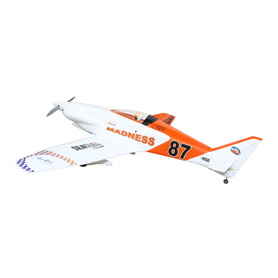
Specifications:
Wing span ------------------------------70.9in (180cm).
Wing area -----------------582.8sq.in (37.6sq dm).
Weight ------------------------7.1lbs (3.2kg).
Length ------------------------------47.1in (119.6cm).
Engine ------------------ 0.55cu.in ----2-stroke.
0.72cu.in ----4-stroke.
Radio -------------------4 channels with 5 servos.
Electric conversion: optional
Flying skill level intermediate /advanced.
Advertisement
Table of Contents

Related Manuals for Seagull Models Grove GR7Madness


Summary of Contents for Seagull Models Grove GR7Madness
- Page 1 MS:168 ASSEMBLY MANUAL “Graphics and specifications may change without notice”. Specifications: Wing span ------------------------------70.9in (180cm). Wing area -----------------582.8sq.in (37.6sq dm). Weight ------------------------7.1lbs (3.2kg). Length ------------------------------47.1in (119.6cm). Engine ------------------ 0.55cu.in ----2-stroke. 0.72cu.in ----4-stroke. Radio -------------------4 channels with 5 servos. Electric conversion: optional Flying skill level intermediate /advanced.
-
Page 2: Kit Contents
Instruction Manual. INTRODUCTION. Thank you for choosing the GROVE GR7 MADNESS ARTF by SEAGULL MODELS COMPANY LTD. The GROVE GR7 MADNESS was designed with the intermediate/advanced sport flyer in mind. It is a semi scale airplane which is easy to fly and quick to assemble. The airframe is conventionally built using balsa, plywood to make it stronger than the average ARTF , yet the design allows the aeroplane to be kept light. -
Page 3: Hinging The Aileron
www.seagullmodels.com HINGING THE AILERON . CONTENTS.TS Note: The control surfaces, including the Fuselage ailerons, elevators, and rudder, are Wing Set Tail Set prehinged with hinges installed, but Cowling the hinges are not glued in place. It Canopy is imperative that you properly Wing Tube adhere the hinges in place per the Engine Mount... -
Page 4: Hinging The Elevator
GROVE GR7 MADNESS Instruction Manual. Hinge. 4) Deflect the aileron and completely 5) Turn the wing panel over and deflect the saturate each hinge with thin C/A glue. The aileron in the opposite direction from the ailerons front surface should lightly contact the opposite side. - Page 5 www.seagullmodels.com INSTALL THE AILERONS CONTROL HORN. 1) Locate the hardware necessary to install the control horns for the ailerons. Fiberglass control horn Position the Control horn on the Aileron and use 30-minute Epoxy Epoxy. Fiberglass control horn 2)Position the Control horn on the Aileron and use 30-minute Epoxy Epoxy.
-
Page 6: Installing The Stopper Assembly
GROVE GR7 MADNESS Instruction Manual. INSTALLING THE STOPPER ASSEMBLY. 1) Using a modeling knife, carefully cut off the rear portion of one of the 3 nylon tubes Epoxy. leaving 1/2” protruding from the rear of the stopper. This will be the fuel pick up tube. 2) Using a modeling knife, cut one length of silicon fuel line. -
Page 7: Fuel Tank Installation
www.seagullmodels.com 8) Use plywood template to hold in place 3) Carefully bend the second nylon tube the fuel tank with C/A glue to secure the fuel up at a 45º angle. This tube is the vent tube. tank inside the fuselage. 4) Test fit the stopper assembly into the tank. -
Page 8: Mounting The Engine
GROVE GR7 MADNESS Instruction Manual. 2mm. Throttle servo. Rudder servo. Elevator servo. 3) Use a drill to drill the four holes in the engine mount rails. THROTTLE SERVO ARM INSTALLATION. Install adjustable servo connector in the servo arm as same as picture below: Loctite secure. - Page 9 www.seagullmodels.com 8) Reinstall the servo horn by sliding the connector over the pushrod wire. Center the Trim and cut. throttle stick and trim and install the servo horn perpendicular to the servo center line. Trim and cut. 9) Move the throttle stick to the closed position and move the carburetor to closed.
- Page 10 GROVE GR7 MADNESS Instruction Manual. Recommendation EP parts as shown (not included with your model) Needle valve. - Model size: .45-.52 size models - Motor: 35mm 830 rev per volt - Propeller: 12x6-13x6 - ESC: 50A - Lipo Batteries: 4 cell 3200mA 2) Attach the electric motor box to the firewall suitable with the cross lines drawn on the electric motor box and firewall.
- Page 11 www.seagullmodels.com M3x15mm. 4mm. Epoxy. 110mm. Balsa stick. 4mm. Epoxy. Electric motor. Blind nut. Battery.
-
Page 12: Installing The Spinner
GROVE GR7 MADNESS Instruction Manual. 4) Attach the speed control to the side of the INSTALLING THE AILERON motor box using two-sided tape and tie wraps. Connect the appropriate leads from the speed control to the motor. Make sure the leads will not interfere with the operation of the motor. - Page 13 www.seagullmodels.com 3) Apply 2-3 drops of thin C/A to each of the mounting holes. Allow the C/A to cure without 7) A string has been provided in the wing to using accelerator. pull the aileron lead through to the wing root. Remove the string from the wing at the servo location and use the tape to attach it to the servo extension lead.
-
Page 14: Installing Landing Gear
GROVE GR7 MADNESS Instruction Manual. 60mm. M2 clevis. M2 lock nut. 100mm. Wing. M2 lock nut. Aileron. INSTALLING LANDING GEAR 9) Set the aileron hatch in place and use a 1)Locate items necessary to install Spring Phillips screw driver to install it with four wood Landing Gear. - Page 15 www.seagullmodels.com Epoxy. M3x15mm. 3)Install Fiberglass Wheel Pants into Wings. Epoxy. 2mm. Drill 2mm.
-
Page 16: Installing The Horizontal Stabilizer
GROVE GR7 MADNESS Instruction Manual. M3x10mm. Screw. 4)Install Wheels. Drill 4.2mm. INSTALLING THE HORIZONTAL STABILIZER. 1) Using a ruler and a pen, locate the centerline of the horizontal stabilizer, at the trail- ing edge, and place a mark. Use a triangle and extend this mark, from back to front, across the top of the stabilizer. - Page 17 www.seagullmodels.com Draw center line. Pen. 2) Using a modeling knife, carefully remove 5) Remove the stabilizer. Using the lines the covering at mounting slot of horizontal sta- you just drew as a guide, carefully remove the bilizer ( both side of fuselage). covering from between them using a model- ing knife.
- Page 18 GROVE GR7 MADNESS Instruction Manual. While holding the vertical stabilizer 7) When you are sure that everything is aligned correctly, mix up a generous amount firmly in place, use a pen and draw a line on of 30 Minute Epoxy. Apply a thin layer to the each side of the vertical stabilizer where it top and bottom of the stabilizer mounting area meets the top of the fuselage.
-
Page 19: Mounting The Tail Wheel
www.seagullmodels.com MOUNTING THE TAIL WHEEL. 1) Locate the items for this section of the manual. HINGING THE RUDDER. Glue the rudder hinges in place using the same techniques used to hinge the ailerons. Epoxy. M3x12mm. - Page 20 GROVE GR7 MADNESS Instruction Manual. Elevator control horn. C/A glue. Rudder control horn. Elevator control horn. 3) Thread one clevis and M3 lock nut on to each elevator control rod. Thread the horns Plastic part. on until they are flush with the ends of the con- trol rods.
- Page 21 www.seagullmodels.com Elevator pushrod. Control horn. Elevator pushrod. Control horn. Rudder pushrod. Elevator pushrod. RUDDER PUSHROD HORN C/A glue. INSTALLATION. Elevator pushrod. 580mm. M2 clevis. M2 lock nut. 620mm. Rudder pushrod. C/A glue.
-
Page 22: Apply The Decals
2) A scale pilot is included with this ARF. The Seagull Pilot included fitting well to the cockpit. (or you can order others scale pilot figures made by Seagull factory. They are available at Seagull distributors.) - Page 23 www.seagullmodels.com 3) Route the antenna in the antenna tube Screw. inside the fuselage and secure it to the bot- tom of fuselage using a plastic tape. M3x12mm. ATTACHMENT WING-FUSELAGE. M3x12mm. Attach the carbon fiber into fuselage. Wing tube. Insert two wing panels as pictures below. BALANCING.
-
Page 24: Control Throws
GROVE GR7 MADNESS Instruction Manual. Accurately mark the balance point on the top of the wing on both sides of the fuselage. The balance point is located 67 mm back from the leading edge of the wing at the wing root. This is the balance point at which your model should balance for your first flights. -
Page 25: Flight Preparation
www.seagullmodels.com PREFLIGHT CHECK. FLIGHT PREPARATION. 1) Completely charge your transmitter A) Check the operation and direction of and receiver batteries before your first day of the elevator, rudder, ailerons and throttle. flying. Plug in your radio system per the 2) Check every bolt and every glue joint manufacturer's instructions and turn every- in the GROVE GR7 MADNESS to ensure that thing on.
Need help?
Do you have a question about the Grove GR7Madness and is the answer not in the manual?
Questions and answers