Advertisement
Quick Links
Advertisement

Related Manuals for Borg & Overstrom 628


Summary of Contents for Borg & Overstrom 628
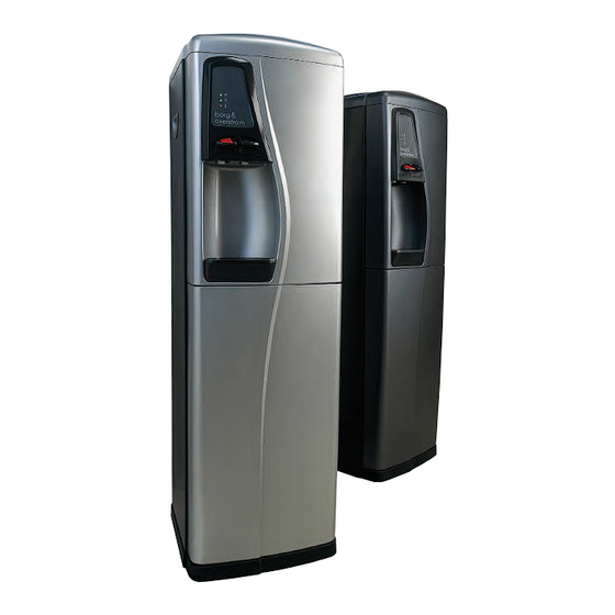
- Page 1 INSTALLATION & OPERATION GUIDE 628 & 698 MODELS...
- Page 2 Technical Manual 628 & 698 Models Contents Range Overview ........Page 4 Installation &...
- Page 3 Technical Manual Section1...
- Page 4 628 & 698 Models Range Overview A comprehensive range of watercoolers, available in two different operational types: • “Classic”- Reservoir Model (Cold Water Storage Tank) • “Direct Chill” Model (No Stored Drinking Water) Both types are available as: • Floorstanding •...
- Page 5 628 & 698 Models All types All b & o “Classic” & “Direct Chill” models are self contained machines with robust steel sided cabinets and attractively moulded front and top panels. An IEC Power Lead is supplied for connection to the IEC socket found on the rear of all models.
- Page 6 628 & 698 Models Controls Cold & Ambient Models Electrical On/Of switch - At upper rear of machine. Switches on Cooling Operation. Cold Thermostat - At rear of machine. On Classic models and inside the machine, next to the Chill Tank, on DC Models.
- Page 7 Technical Manual Section 2...
- Page 8 628 & 698 Models CW698 Installation and Operational Guide IMPORTANT - the guide must be read before attempting to connect the machine. Introduction Congratulations on your wise choice of water cooler. Your Borg & Overström water cooler will provide you with a continuous supply of water 24 hours a day.
- Page 9 628 & 698 Models Top cover Baffle plate Float valve Indicator panel Taps Drip Tray Hot & cold switches Inlet Sanitisation & Cleaning 1. Please make sure that the machine has been disconnected from the electrical supply before any cleaning commences.
- Page 10 628 & 698 Models DC698 Installation and Operational Guide IMPORTANT - the guide must be read before attempting to connect the machine. Introduction Congratulations on your wise choice of water cooler. Your Borg & Overström water cooler will provide you with a continuous supply of water 24 hours a day.
- Page 11 628 & 698 Models Top cover Cover of Header Tank Ice Bank Header Tank Float Valve Indicator Panel Cold Water Button Hot Water Button Drip Tray Hot & cold switches Inlet Sanitisation & Cleaning 1. To commence sanitisation, simply isolate the water supoply and remove the filter cartridge.
- Page 12 628 & 698 Models CW628 Installation and Operational Guide IMPORTANT - the guide must be read before attempting to connect the machine. Introduction Congratulations on your wise choice of water cooler. Your Borg & Overström water cooler will provide you with a continuous supply of water 24 hours a day.
- Page 13 628 & 698 Models Hot & cold switches Inlet Top Cover Baffle Pipe Float Valve Indicator Panel Taps Drip Tray Sanitisation & Cleaning 1. Please make sure that the machine has been disconnected from the electrical supply before any cleaning commences.
- Page 14 628 & 698 Models Cup Dispenser 1. Carefully unpack and inspect for damage. 2. Select fitting position (Normally at top of right hand side panel towards front of machine). 3. Attach self adhesive pad to mounting bracket and affix to chosen site (Clean area first to ensure good adhesion).
- Page 15 628 & 698 Models LEAK DETECTOR Installation and Operational Guide IMPORTANT - the guide must be read before attempting to connect the machine. Introduction Congratulations, you have chosen wisely to add a Leak Detector to your Borg & Overström water cooler.
- Page 16 628 & 698 Models Installation & Operation This product can only be used in conjunction with a Borg & Overström water cooler. Please follow the step-by-step procedures for installation: 1. Please fix the Leak Detector as high as possible within the machine.
- Page 17 628 & 698 Models Installing the Level Sensor 698/698H Models: 1. Ensure water and electricity supplies to machine are switched off. 2. Remove Tap Cover Panel and disconnect PCB 3. Remove Front Panel. (Be ready to catch Lower Door when lifting Front Panel Clear) Fig.1...
- Page 18 628 & 698 Models The Waste Kit • Remove Filter Bracket from base of machine and place container inside • Remove top lid. This will allow access to the rear of the drip tray area. • Connect the 2 lengths of silicone tube together using the 90 degree elbow •...
- Page 19 Technical Manual Section 3...
- Page 20 628 & 698 Models Sanitisation Guide Direct Chill Water Coolers Turn off incoming mains water, briefly press dispense button(s) to release internal water pressure from the machine and remove filter. If possible temporarily shut off inlet to any hot tank as sanitisation of a hot tank in continuous use is unnecessary.
- Page 21 628 & 698 Models Sanitisation Guide Reservoir Water Coolers Please make sure that the machine has both been switched off and disconnected from the electrical supply and that the water is turned off, use the taps (and drain point if fitted) to drain off all the water, before any cleaning commences.
- Page 22 628 & 698 Models Descaling Guide Reservoir Model Scale deposits will occur whenever water is heated. Higher deposits will occur with harder water and higher temperatures. Although scale deposits can be reduced through using softened water this is not necessarily desirable due to the adverse effect on taste.
- Page 23 Technical Manual Section 4...
- Page 24 628 & 698 Models...
- Page 25 628 & 698 Models...
- Page 26 628 & 698 Models...
- Page 27 628 & 698 Models...
- Page 28 628 & 698 Models...
- Page 29 628 & 698 Models...
- Page 30 628 & 698 Models...
- Page 31 628 & 698 Models...
- Page 32 628 & 698 Models...
- Page 33 628 & 698 Models...
- Page 34 628 & 698 Models...
- Page 35 Technical Manual Section5...
- Page 36 628 & 698 Models B B org & Overstrom Classic 628 Cold & Ambient/Countertop Exploded Component View Production no 628-10 Jan 2009...
- Page 37 628 & 698 Models B B org & Overstrom Classic 628H Hot & Cold/Countertop Exploded Component View Production no 628-10H Jan 2009...
- Page 38 628 & 698 Models B B org & Overstrom Classic 698 Cold & Ambient/Floorstanding Exploded Component View Production no 698-10 Jan 2009...
- Page 39 628 & 698 Models B B org & Overstrom Classic 698H Hot & Cold/Floorstanding Exploded Component View Production no 698H-10 Jan 2009...
- Page 40 628 & 698 Models Borg & Overstrom 628/698 Cold & Ambient Ambient Electrical Diagram...
- Page 41 628 & 698 Models Borg & Overstrom 628/698 Hot & Cold Production series No 10...
- Page 42 Technical Manual Section6...
- Page 43 628 & 698 Models Azure Ref QTY 628 QTY 698 Exploded Diagram Reference Azure Part No. C&A H&C DC C&A H&C DC CW628 628H 628DC 698H 698DC 123817 Inner Top Panel-Silver 123826 Inner Top Panel-Graphite 123815 Outer Top Panel-Silver 123826...
- Page 44 DC Tank Pipe Connector 154522 Hot Vent Pipe 154521 Hot Vent Pipe 154524 Hot Tank Feed Pipe 154526 628 Hot Tank Drain Pipe 154525 Hot Vent Pipe Fitting Hot Vent Pipe cover 151543 Hot Vent Filter 628 Drain Bung 154411...
- Page 45 628 Polystyrene Carton Base 128901 698 B&O Carton 128201 628 B&O Carton 128902 698 Poly Bag 128202 628 Poly Bag 128803 628/698 Polystyrene Carton Top 1 173250 87C Hot Conversion Kit Silicone Drainage Tube 171205 PCB-Hot 87C Conversion 15142 Hot Tank Bung...
- Page 46 628 & 698 Models MACHINES CW698 Floorstanding Cold and Ambient CW698 Floorstanding Cold and Ambient Graphite CW698H Floorstanding Cold and Hot Silver CW698H Floorstanding Cold and Hot Graphite CW628 Countertop Cold and Ambient Silver CW628 Countertop Cold and Ambient Graphite...
- Page 47 Technical Manual Section7...
- Page 48 628 & 698 Models Borg & Overstrom Product List Azure Product Code Azure Product Reference PANELS 120215 Front Panel 628 - Silver (with drip) 120217 Front Panel 728 - Silver 120224 Front Panel 628 - Graphite (no Drip) 120225 Front Panel 628 - Graphite (with drip)
- Page 49 628 & 698 Models 123817 Inner top Panel - Silver 123820 Outer Panel Complete-Graphite (old) 123825 Outer top panel - Graphite (old) 123826 Outer Panel - Graphite (new) 123827 Inner top Panel - Graphite 124251 Base Panel-628 124951 Base Panel-698...
- Page 50 628 & 698 Models 131579 Reservoir Float Valve Washer 131641 1/4" push-Fit Inlet Connector 131642 1/4" Push Fit Inlet Elbow 131643 1/4" Stem Elbow 131644 1/4" Push-Fit 4 way Joint 131645 90 degree elbow fitting (for drainage) 131646 Air Vent Elbow fitting for Clip-on Tank Lid...
- Page 51 154526 Straight Type Silicon Tube 154527 Z-Type Silicon Tube 154528 Checking Valve 154529 628 Hot Tank Drain Pipe, 5kg reel 154531 628 Hot Tank Drain Pipe, 35mm long TANKS 165230 Cold Reservoir Set 166770 Hot Tank c/w HB, 1 sensor & NTC Probe...
- Page 52 628 & 698 Models 166872 Hot Tank c/w 87 TC set 166920 Hot Tank c/w 92TC set and heater band 167240 DC Cold Tank Set ELECTRICAL 171201 PCB Cold 698 171202 PCBoard 171203 PCB-Hot 92NTC 171204 PCB-DC 171211 PCB Cold 798...
- Page 53 628 & 698 Models 173258 82C Hot Tank Thermostat 173259 90C Temperature Sensors 173261 82/92 Upgrade Kit 173262 Cold Thermostat 818 173450 Hot Upgrade Kit 90C/97C (92C) 174231 Elec Rocker Switch 174310 DC Tank Pump Set 174311 Compressor Wire Cover...
- Page 54 628 & 698 Models 182461 M4 x7 S/S PHD M/Screws 183241 Back Nut 183242 698 Hot Tank/DC Drain Nut 184531 Adjustable Foot for 798/728 184541 Fixture Sheet for Cup Dispenser 184542 Spring Cover for Cup Dispenser 184543 Rubber Sheet for Cup Dispenser...
- Page 55 628 & 698 Models MACHINES 105910 Floorstanding Cold and Ambient Silver 105920 Floorstanding Cold and Ambient Graphite 106910 Floorstanding Cold and Hot Silver 106920 Floorstanding Cold and Hot Graphite 105210 Countertop Cold and Ambient Silver 105220 Countertop Cold and Ambient Graphite...
- Page 56 628 & 698 Models RETURNS NOTE Azure Service No: IMPORTANT: TO ENABLE US TO PROCESS YOUR CLAIM AS QUICKLY AS POSSIBLE, PLEASE FULLY COMPLETE ALL SECTIONS, FOLLOWING THE PROCEDURE DETAILED OVERLEAF. CREDIT WILL NOT BE CONSIDERED UNLESS THIS NOTE IS FULLY COMPLETED AND ENCLOSED WITH THE RETURNED ITEM(S) WITHIN FOURTEEN DAYS OF THE SUPPLY OF THE REPLACEMENT ITEM.
- Page 57 628 & 698 Models Azure Returns Procedure If you want to return any of your items please follow the instructions below • An Azure Service Number must be obtained prior to returning any goods by calling Azure Service on : 0845 450 30 90.
- Page 58 Technical Manual Section8...
-
Page 59: Table Of Contents
628 & 698 Models STEP-BY-STEP PROCEDURES Contents Hot Tank Replacement Procedure ........... . . Page 60-62 Procedure for Upgrading Hot Water Temperature Control System . -
Page 60: Hot Tank Replacement Procedure
628 & 698 Models Hot Tank Replacement Procedure Tools Required 10-Ltr Bucket 1Litre jug *1Pt Long Blade Phillips Screwdriver (250mm blade min) Flat Blade Screwdriver Side Cutters Estimated time 20 minutes *Preferable, otherwise a standard short bladed version can be used. - Page 61 628 & 698 Models 6. View of the Hot Tank inside the machine. 7. At this stage, determine which type of Hot Tank is fitted. a) Internal Element Tank b) Thermister Probe Tank c) External Thermostat (Discontinued-Can be (NB. External sensor...
- Page 62 628 & 698 Models 11. Disconnect the heater power block, carefully remove the tie wrap (with cutters) and remove the Tank. 12. Before fitting the new Hot Tank, ensure the Heater Element is securely fitted (as shown) and depending on the replacement Hot Tank type, either with one or two of the external sensors.
-
Page 63: Procedure For Upgrading Hot Water Temperature Control System
628 & 698 Models Procedure for Upgrading Hot Water Temperature Control System Tools required: PH1 Philips Screwdriver Part required: B & O Hot Upgrade Kit... - Page 64 628 & 698 Models Fig 1. Remove Top Lid of the cooler and then carefully remove the Tap Cover from the front panel by squeezing and then lifting off away from front. Fig 2. Disconnect both large and small plugs.
- Page 65 628 & 698 Models Fig 4. Replace with new circuit board, as supplied. Fig 5. Remove screws holding condenser and very carefully ease condenser away as shown below in Fig 6. Fig 6. Access now possible to Hot Tank. If also replacing Hot Water Tank follow Hot Water Tank Replacement Procedure sections 7-15 at this stage.
- Page 66 628 & 698 Models Fig 7. Remove the Thermistor Probe (with black wire) complete with the clear silicone rubber holder. Fig 8. Bung hole with cap, as supplied. Fig 9. Remove the existing Overload Thermostat.
- Page 67 628 & 698 Models Fig 10. Fit new Overload Thermostat (with button) to top position and Thermostat (without button) to bottom. Ensure that the white Heat Transfer Paste is already applied to the back of the thermostats before fitting. Fig 11.
- Page 68 628 & 698 Models Fig 13. Feed out of hole in front panel ready to plug onto new circuit board. Fig 14. Attach the two connectors on the other end to each of the terminals on the bottom Tank Thermostat.
- Page 69 628 & 698 Models Fig 16. Draw out inlet end of water pipe tubing from back of machine, leaving attached at inlet valve end. Fig 17. Carefully rotate push fit elbow half a full turn clockwise and re-route water pipe tubing around right hand side of tank and down and out of rear of machine.
-
Page 70: Water Tubing Replacement - Step-By-Step Guide
628 & 698 Models Water Tubing Replacement - Step by Step Guide 1. Remove the two retaining 2. Disconnect existing white 3. Disconnect other end of screws from the back of top tubing from push-fit elbow existing white tubing from lid and remove lid. - Page 71 628 & 698 Models Water Tubing Replacement- Step by Step Guide continued 7. Continue to feed the end of 8. Connect the tubing to the 9. Route the replacement tube the tube downwards and Bulkhead fitting (if required) clockwise around the top...
-
Page 72: Procedure For Checking The Compressor/ Cooling Operation
628 & 698 Models Azure Technical Advice Procedure For Checking the Compressor/ Cooling Operation If the Compressor does not run: 1. Check the LED display For Cold & Ambient models the green (top) LED should always be on and the Yellow (Bottom) when cooling is called for. - Page 73 628 & 698 Models If the Compressor Does Run (Presuming that the Cold water is not being cooled sufficiently) 1. Check the small pipe on the ‘high’ side of the compressor. This should be quite warm after several minutes of normal operation.
-
Page 74: Solenoid Valve Replacement
628 & 698 Models Solenoid Valve Replacement 1. Turn off the water supply, press dispense buttons to release water pressure and disconnect electrical power lead. 2. Carefully remove Top Cover, Keypad Panel and Front Panel from machine 3. Pull off Faucet (A). - Page 75 Notes...
- Page 76 Notes...
- Page 77 Notes...
- Page 78 Notes...
- Page 79 Notes...
- Page 80 Notes...
- Page 81 INSTALLATION & OPERATION GUIDE 628 & 698 MODELS Head office: 31 Bolling Road, Bradford, BD4 7HN Contact: 01226 720 490, info@refreshmentsystems.co.uk...
Need help?
Do you have a question about the 628 and is the answer not in the manual?
Questions and answers