Table of Contents
Advertisement
Install & Operation Manual
Dispense options
Chilled & Ambient
Chilled, Ambient & Hot
Chilled, Ambient & Sparkling
Chilled, Hot & Sparkling
Contents
2
5
7
11
16
21
28
Telephone
+44 (0)1362 695 006
Email
Synergy House
sales@borgandoverstrom.com
Fakenham Road
Morton On The Hill
borgandoverstrom.com
NR9 5SP
Chilled
Exploded Diagrams
Technical Information
28 Electrical Circuit Diagrams
32 Flow Diagrams
Ambient
AU
Advertisement
Table of Contents

Related Manuals for Borg & Overstrom B4


Summary of Contents for Borg & Overstrom B4
-
Page 1: Table Of Contents
Install & Operation Manual Dispense options Chilled & Ambient Chilled, Ambient & Hot Chilled, Ambient & Sparkling Chilled, Hot & Sparkling Chilled Ambient Contents Model Overview 2 Introduction 3 Controls 4 Floor standing Version Installation 5 Major Components 5 Water and CO2 Connection 6 Level Sensor Assembly Operation 7 Water Connection &... -
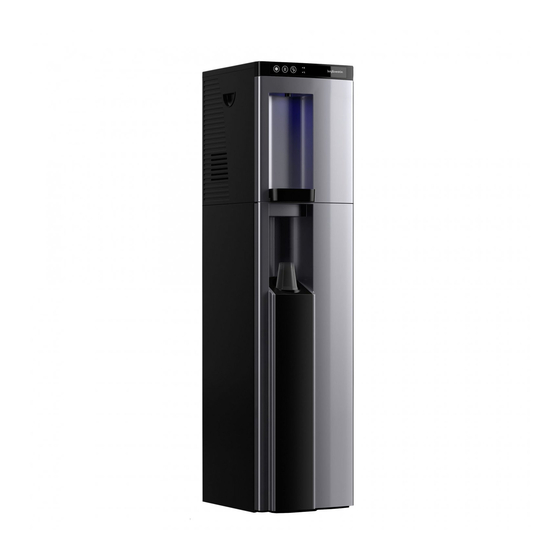
Page 2: Model Overview
• Direct Chill Chilled, Ambient & Sparkling • Direct Chill Chilled, Hot & Sparkling The B4 model is available as a countertop with a matching base cabinet in three colours. All Models Ambient All models are self-contained machines with Water bypasses the cold tank for the robust steel framed cabinets and attractively ambient dispense. -
Page 3: Controls
Press again to dispense hot water. Ambient Button: Press to dispense (Note: Machine will revert to locked after 5 ambient water. seconds if dispense is not activated.) Hot LED: Indicates hot application is switched on. Borg & Overström B4.2 Install & Operation Manual... -
Page 4: Floor Standing Version
• Sensor unit (c/w 2 no. CR3032 batteries). (Requires some assembly – see page 7. • Drip Tray with Drainage Outlet. • Interconnection kit between unit and cabinet – see page 25. Borg & Overström B4.2 Install & Operation Manual... -
Page 5: Installation
(Behind the front panel) Drip Tray Water & CO2 Connection Carbonation Switch On/Off Switch IEC Power Socket CO2 Connector (1/4”) Inlet Water (1/4”) Cold Drain Port Hot Drain Port Caution when draining hot tank Borg & Overström B4.2 Install & Operation Manual... -
Page 6: Level Sensor Assembly
NOTE: A WARNING TONE WILL SOUND WHEN THE WATER RISES (3 BEEPS EVERY 15 SECONDS REPEATED). UPON EMPTYING THE CONTAINER THE WARNING TONE WILL STOP. CONTINUAL BEEP INDICATES LOW BATTERY POWER. Borg & Overström B4.2 Install & Operation Manual... -
Page 7: Operation
All hot & sparkling tanks must carbonation switch on the back be lit. be purged of air by holding the of the unit. corresponding button. Do not switch the hot system on until tank has been purged. Borg & Overström B4.2 Install & Operation Manual... - Page 8 4c to 11c. immediately after installing and indicator will be lit. Allow up to 1 hour for the water to reach its minimum before use. temperature. Borg & Overström B4.2 Install & Operation Manual...
-
Page 9: Co2 Bottle Installation
Flush through approximately 10 litres of Following installation, it will be necessary sparkling water. Check and adjust the to leave the machine for up to 1 hour for CO2 pressure accordingly. the initial chilling cycle to occur. Borg & Overström B4.2 Install & Operation Manual... -
Page 10: Functions & Controls
Leave a space no less than 15cm between the wall and dispenser. • When combined with base cabinet - use wall bracket kit for high traffic areas. • Keep the machine away from sunlight, heat and moisture. 15cm Borg & Overström B4.2 Install & Operation Manual... -
Page 11: Maintenance
Hot water drain Caution when draining hot tank To drain the Direct Chill tank, remove the caps on the back of the machine. We recommend they are refitted immediately upon draining being completed. Borg & Overström B4.2 Install & Operation Manual... -
Page 12: Sanitisation Guide
Briefly press the ambient machine externally, pay Remember to include the drip button too. particular attention to the tray and connecting pipe work. dispense faucet and buttons. Borg & Overström B4.2 Install & Operation Manual... - Page 13 In the event of any skin including metals, can cause damage. Always rinse contact, flush immediately all contact surfaces after use with clean water. with clean, cold water Borg & Overström B4.2 Install & Operation Manual...
-
Page 14: Leak Detection
Reconnect the power to machine fitted as optional extra: locate and test operation. the Leak Detector valve. If leak detector is fitted as optional extra, reset the red lever (push it in) Borg & Overström B4.2 Install & Operation Manual... -
Page 15: Emptying The Carbonation Tank
The tank is empty of sparking water when only Ensure to release the Sparkling water button and CO2 is being released. take care to avoid releasing excess amounts of CO2 gas. Borg & Overström B4.2 Install & Operation Manual... -
Page 16: Advanced Troubleshooting
Thaw out the machine and check working. thermostat. Replace Cold Water thermostat as needed. Chiller tank frozen. Circulation pump not working / Thaw out the machine and check circulation pump. Replace circulation pump as needed. Borg & Overström B4.2 Install & Operation Manual... - Page 17 6. Wait for the pump to stop running. 7. Re-open CO2 supply. Pump Feed Solenoid Valve. Check function/condition and repair/replace accordingly. Carbonation System switched off. Switch on (Switch on back of the machine). Borg & Overström B4.2 Install & Operation Manual...
- Page 18 Hot tank heavily scaled (signs of Carry out thorough descale or scale in top of tank, loud boiling replace hot tank. noises etc). Break in supply wiring to main Locate break and repair. element. Borg & Overström B4.2 Install & Operation Manual...
- Page 19 Replace missing fixings. Tripping out Electricity Supply Machine in high humidity Discuss possible repositioning with environment. customer. Electrical circuitry faults. Test, identify and address accordingly. See Electrical Diagrams. Please contact technical support Borg & Overström B4.2 Install & Operation Manual...
- Page 20 Continuous Water Dispense from Button jammed on/faulty. Replace PCB or/button panel as Ambient/Cold or Hot water valve. needed. Debris blocking hole in diaphragm Dismantle valve and clean out. window. Borg & Overström B4.2 Install & Operation Manual...
- Page 21 173241 172144 172148 852108 173241 172152 121851 131426 174231 172163 173264 171268 174313 171260 172223 171268 171264 133514 174351 462325 120803 171265 171269 174392 121850 183246 191003 120802 125839 120800 125840 120801 Borg & Overström B4.2 Install & Operation Manual...
- Page 22 173241 166986 173241 132445 121851 173241 131426 174231 174231 172163 171268 173264 174313 171261 172223 171268 171264 133514 174351 120803 171265 462325 171269 174392 121850 183246 191004 120802 120800 125839 120801 125840 Borg & Overström B4.2 Install & Operation Manual...
- Page 23 173241 131426 121851 174231 174231 172163 174313 120802 172223 120800 120801 174351 173241 133514 171264 173264 171268 171262 120803 171265 462325 171268 462325 171269 132445 183246 174391 191005 174372 125839 125840 121850 Borg & Overström B4.2 Install & Operation Manual...
- Page 24 121851 173241 173241 174231 174231 172163 173241 120802 120800 172223 174313 120801 174351 133514 171268 173264 171264 171261 120803 171265 171268 462325 171269 462325 132445 183246 174391 191006 174372 125839 125840 121850 Borg & Overström B4.2 Install & Operation Manual...
- Page 25 Base Unit Exploded Diagram 193001 103592 103910 103591 193220 131567 194101 184530 134571 120811 120812 120813 193199 193197 Borg & Overström B4.2 Install & Operation Manual...
- Page 26 B3.2/B4.2 Chilled & Ambient Main PCB 171261 B3.2/B4.2 Chilled, Ambient & Hot Main PCB 171262 B3.2/B4.2 Chilled, Ambient & Sparkling Main PCB 171261 B3.2/B4.2 Chilled, Ambient & Hot/ Chilled, Hot & Sparkling Main PCB 171264 B3.2/B4.2 LED Display PCB 171265 Touch Panel PCB Board 171268 B3.2/B4.2 Main PCB Case Assembly...
- Page 27 Base Cabinet Replacement Foot Set 191003 B4.2 Chilled & Ambient Touch Control Panel 191004 B4.2 Chilled, Ambient & Hot Touch Control Panel 191005 B4.2 Chilled, Ambient & Sparkling Touch Control Panel 191006 B4.2 Chilled, Hot & Sparkling Touch Control Panel...
- Page 28 PURPLE CONDENSER FAN BROWN BLUE TEMPERATURE PROBE WHITE YELLOW ORANGE COMPRESSOR TRANSFORMER SWITCH SOLENOID FUSE PUMP BRIDGE DIODE TEMPERATURE SWITCH HOT WATER TANK LED DISPLAY PCB TOUCH SCREEN LEAK DETECTION LEVEL SENSOR Borg & Overström B4.2 Install & Operation Manual...
- Page 29 PURPLE BROWN CONDENSER FAN BLUE WHITE TEMPERATURE PROBE YELLOW ORANGE COMPRESSOR TRANSFORMER SWITCH SOLENOID FUSE PUMP BRIDGE DIODE TEMPERATURE SWITCH HOT WATER TANK LED DISPLAY PCB TOUCH SCREEN LEAK DETECTION LEVEL SENSOR Borg & Overström B4.2 Install & Operation Manual...
- Page 30 BROWN CONDENSER FAN BLUE TEMPERATURE PROBE WHITE YELLOW ORANGE COMPRESSOR TRANSFORMER SWITCH SOLENOID FUSE PUMP BRIDGE DIODE TEMPERATURE SWITCH HOT WATER TANK OTOR LED DISPLAY PCB TOUCH SCREEN LEAK DETECTION LEVEL SENSOR Borg & Overström B4.2 Install & Operation Manual...
- Page 31 CONDENSER FAN PURPLE BROWN TEMPERATURE PROBE BLUE WHITE YELLOW COMPRESSOR ORANGE TRANSFORMER SWITCH SOLENOID FUSE PUMP BRIDGE DIODE TEMPERATURE SWITCH HOT WATER TANK OTOR LED DISPLAY PCB TOUCH SCREEN LEAK DETECTION LEVEL SENSOR Borg & Overström B4.2 Install & Operation Manual...
- Page 32 Chilled & Ambient Water Pathway Diagram AMBIENT CHILLED VENT LINE FAUCET DIRECT CHILL TANK & COMPRESSOR DRAIN AMBIENT WATER SOLENOID COLD WATER SOLENOID GRIT FILTER WATER IN Borg & Overström B4.2 Install & Operation Manual...
- Page 33 Chilled, Ambient & Hot Water Pathway Diagram AMBIENT CHILLED VENT LINE EXHAUST FAUCET DIRECT CHILL TANK & COMPRESSOR TANK DRAIN AMBIENT WATER SOLENOID DRAIN CHILLED WATER SOLENOID GRIT FILTER WATER IN HOT WATER SOLENOID Borg & Overström B4.2 Install & Operation Manual...
- Page 34 NON RETURN VALVE SPARKLING WATER SOLENOID SPARKLING TANK SOLENOID CARBONATION MOTOR COLD WATER SOLENOID DIRECT CHILL TANK FAUCET & COMPRESSOR DRAIN AMBIENT WATER SOLENOID DIRECT CHILL TANK SOLENOID GRIT FILTER WATER IN Borg & Overström B4.2 Install & Operation Manual...
- Page 35 NON RETURN VALVE SPARKLING WATER SOLENOID SPARKLING TANK SOLENOID COLD WATER CARBONATION SOLENOID MOTOR DIRECT CHILL TANK FAUCET & COMPRESSOR DRAIN DRAIN HOT TANK SOLENOID DIRECT CHILL TANK SOLENOID GRIT FILTER WATER IN Borg & Overström B4.2 Install & Operation Manual...
- Page 36 (w x d x h) 320 x 440 x 415mm (INCLUDING BASE CABINET) (w x d x h) 1325 x 440 x 415mm WEIGHTS Chilled & Ambient 14.5kg Chilled & Hot 16.2kg Chilled & Sparkling 21.0kg Chilled, Hot & Sparkling 22.9kg Borg & Overström B4.2 Install & Operation Manual...
- Page 37 Borg & Overström B4.2 Install & Operation Manual...
- Page 38 Borg & Overström B4.2 Install & Operation Manual...
- Page 39 Borg & Overström B4.2 Install & Operation Manual...
- Page 40 © Copyright Borg & Overström. This manual is printed by Borg & Overström and shall not be reproduced or copied in anyway. Document Reference: B4.2.I&OM.AU.170820 Borg & Overström B4.2 Install & Operation Manual...
Need help?
Do you have a question about the B4 and is the answer not in the manual?
Questions and answers