Table of Contents
Advertisement
Quick Links
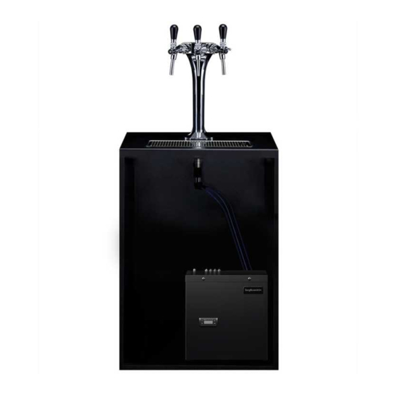
u2 40L - Install & Operation Manual
Dispense options
Chilled, Ambient & Sparkling
Contents
2
3
5
15
18
21
23
26
29
Telephone
+44 (0)1362 695 006
Email
sales@borgandoverstrom.com
borgandoverstrom.com
Synergy House
Fakenham Road
Morton On The Hill
NR9 5SP
Chilled
Model Overview
Component/Feature Overview
Installation
Operation
Maintenance & Cleaning
Advanced Troubleshooting
Exploded Diagrams & Parts List
Technical Information
Declarations of Conformity
Ambient
GB
Advertisement
Table of Contents

Related Manuals for Borg & Overstrom u2 40L


Summary of Contents for Borg & Overstrom u2 40L
- Page 1 40L - Install & Operation Manual Dispense options Chilled, Ambient & Sparkling Chilled Ambient Contents Model Overview Component/Feature Overview Installation Operation Maintenance & Cleaning Advanced Troubleshooting Exploded Diagrams & Parts List Technical Information Declarations of Conformity Telephone +44 (0)1362 695 006 Email sales@borgandoverstrom.com...
-
Page 2: Model Overview
Model Overview Introduction The u2 is a robust, simple to operate to provide ambient still, chilled and and maintain multi-headed tap with an carbonated water. All the materials and aesthetically striking design. components are tested during the entire The under-counter dispenser is a dry production process in order to satisfy all block cooler carbonator designed expectations. -
Page 3: Component/Feature Overview
Component/Feature Overview u2 Tap - Major Components Dispense Lever Cold Water Tap Ambient Water Tap Sparkling Water Tap Main Body Gasket Threaded Stem Contents: & Back Nut 1 no Tap Tower Chilled Water Pipe 2/3 no Tap Spacers Sparkling Water Pipe 2/3 no Tap Lever sets 1 no u2 Dispense Label Set Ambient... -
Page 4: Major Components
Major Components Chilled Water Outlet Sparkling Water Outlet Water Inlet Ambient Water Outlet CO2 Inlet Top Panel Power Connection Eliwell Control Panel Unit Carry Handle Side Panel Front Panel Contents: 1 no Undercounter Unit 1 no 2.0m Power Cord Set 1 no Co2 Regulator with Gauge &... -
Page 5: Tap Installation
Installation Tap Installation Identify a suitable location for the undercounter unit. It should be positioned within 1.0m of the faucet, and within 2.0m of a suitable services connections: Service Requirements Water: Mains potable water – 2.0bar recommended. Min 1.0bar Electricity: 13A supply – Earth Leakage Protected. 50mm/35mm When planning and providing Identify a suitable position for... - Page 6 470mm 70mm Also allow for the height Allow for the space needed Allow sufficient space for fitting a of the tap levers under any for forming the required hole. back nut to the faucet stem. overhanging cupboard/shelf. Relate the selected position to the underneath of the counter and check for any obstructions.
- Page 7 Tap Dimensions 215mm 240mm 150mm 240mm Footprint Dimensions 120mm 103mm Three Head 126.5mm Two Head 108mm Borg & Overström Install & Operation Manual...
- Page 8 Driptray Dimensions 400mm 430mm Section A - A 12.7mm Waste Spigot Borg & Overström Install & Operation Manual...
- Page 9 Ventilation System Installation When Borg & Overström u2 undercounter performance of the unit. The amount of heat units are installed inside a cabinet or generated by the cooling cycle depends housing, adequate ventilation is directly upon the amount of usage – the recommended to ensure that they operate higher the usage, the more heat produced.
- Page 10 Ducting Box Air Ducting Insert ducting box into its cut slot in the Bottom panel. Then insert the air ducting into the ducting box until it reaches its limits. Then cut the air ducting so that it is flush with the kickboard. Centrally locate the ventilation grille over the kick board cut out, then using self tapping screws, secure the kick plate.
- Page 11 Undercounter Installation & Water Connection 40 PSI Locate the machine in a Connect the u2 tap to the Connect the CO2 supply from Connect the chiller to the Chilled, Ambient and Sparkling gas regulator, ensuring the suitable enclosure, ensuring water supply and open the water outlets.
- Page 12 Co2 Pipe Water Pipe Co2 Bottle Safety The unit should be isolated from the electricity supply before removal of any covers. Great care must be employed when working with high pressure carbon dioxide, and in no cases should the maximum operating pressure of 58 PSI (4 bar) be exceeded. Borg &...
- Page 13 Sparkling Water Flow Rate NOTE: The soda water flow rate is set to 35ml/sec at a CO2 pressure of 58 PSI (4 bar). To adjust the soda water flow rate follow these steps: Loosen the lock nut, but do Locate the flow control adjuster, Remove the 3 screws holding Flow can then be adjusted not remove.
-
Page 14: General Safety
General Safety • Always place the dispenser in its vertical position, on a surface which can capably support its weight. • During use this machine must remain in its upright position. • Adequate ventilation must be allowed for - we recommend using the supplied ventilation ducting kit. -
Page 15: Operation
Operation Functions & Controls Ambient Water Cold Water Tap SparklingWater Tap CLOSED OPEN OPEN Flow Restrictor Lever Use the valves on the sides of the taps to increase or decrease flow rate. Lever in the upright position is fully closed. Borg &... - Page 16 Eliwell Control Panel Digital Display 8888 Control Button Function Button Control Button Setting Button Controls Power Connection Socket Note: the undercounter unit automatically powers up when the power lead is connected. Basic Settings Adjusting the Set Point: 1. Switch on Mains power – the display will 4.
-
Page 17: Co2 Bottle Installation
CO2 Bottle Installation Unpack CO2 Regulator and fit elbow fitting Attach the regulator to the disposable CO2 Connect the assembled CO2 bottle and to spigot outlet. bottle, ensuring the small pressure relief regulator to the CO2 inlet using a ¼” pipe. vent in the stem is facing away from you or anyone else. -
Page 18: Maintenance And Cleaning
Maintenance & Cleaning Sanitisation Guide NOTE: All maintenance operations must be carried out with the dispenser switched off. This operation must only be carried out by trained staff. Every 6 months a sanitisation procedure is recommended as follows: Turn off incoming mains water. Briefly dispense cold/ambient Remove the existing filter. - Page 19 mins mins For this we recommend the use Pay particular attention to the Attend to any cosmetic marks of Bioguard Foam Descaler & dispense faucets and the tap with Bioguard Rejuvenator & Sanitiser Spray. levers. For this use Bioguard Protector as needed. External Sanitiser &...
- Page 20 Emptying the CO2 Tank Pull and hold the Sparkling water Turn off the water supply. The tank is empty of sparking dispense lever until all the water water when only CO2 is being is expelled and only CO2 gas is released.
-
Page 21: Advanced Troubleshooting
Advanced Troubleshooting Fault Diagnostics Problem/Report Possible Cause Suggested Action No Water Dispensing Water Pressure Regulator Check water tank flow through the regulator. Replace if necessary. No Sparkling Water No CO2 pressure, check by operating Check CO2 bottle, regulator and non- pressure relief valve on carbonator tank return valve. - Page 22 Fault Diagnostics (Continued) Problem/Report Possible Cause Suggested Action Warm Drinks Insufficient cooling air flow through the Check that the condenser is not blocked. fridge. Check supply to cooling fans (230V AC). If supply present replace fans. If supply not present move on to the compressor.
-
Page 23: Exploded Diagrams & Parts List
Exploded Diagrams & Parts List Tap Exploded Diagram 604032 604010 609124 609124 609124 604606 604631 604002 604003 604023 604022 462869 Borg & Overström Install & Operation Manual... - Page 24 Chilled, Ambient & Sparkling Exploded Diagram 632032 637325 637425 462325 462364 637426 462318 462668 462359 635512 462012 462013 462374 462014 462313 637408 637417 462667 637326 462376 637107 462362 637106 632031 462371 462384 462874 462369 462368 Borg & Overström Install & Operation Manual...
- Page 25 Tap Parts List Borg & Overstrom Description Part No 462869 Equal 8mm Elbow 604002 u2 Twin Port Tap Nut 604003 u2 Triple Port Tap Nut 604010 u2 Tap spacer 604022 u2 Twin Port Tap Mounting Gasket 604023 u2 Triple Port Tap Mounting Gasket 604032 u2 Tap Lever with Compensator 604606...
-
Page 26: Technical Information
Technical Information Specification COOLING SYSTEM Stainless steel direct chill coil encased in a solid-block system for instant response cool down action. Ultra efficiency compression system with capillary control. Environmentally friendly R134a refrigerant. COLD TEMPERATURE 2°C - 10°C OUTPUT PER HOUR 40 litres cold and sparkling at <10°C. -
Page 27: Circuit Diagram
Circuit Diagram CONDENSER FAN TEMPERATURE PROBE COMPRESSOR TRANSFORMER SWITCH SOLENOID FUSE BLACK PUMP PURPLE BROWN BRIDGE DIODE BLUE WHITE TEMPERATURE SWITCH YELLOW GREEN CARBONATOR CAN 230 AC INLET Borg & Overström Install & Operation Manual... - Page 28 Water Pathway Diagram AMBIENT CHILLED SPARKLING CO2 IN RETURN VALVE CARBONATION FLOW CONTROL RETURN VALVE CARBONATION TANK RETURN VALVE WATER COIL CARBONATION WATER PRESSURE PUMP REGULATOR WATER IN Borg & Overström Install & Operation Manual...
- Page 29 Borg & Overström Install & Operation Manual...
- Page 30 Borg & Overström Install & Operation Manual...
- Page 31 Borg & Overström Install & Operation Manual...
- Page 32 © Copyright Borg & Overström. This manual is printed by Borg & Overström and shall not be reproduced or copied in anyway. Document Reference: u2.40.I&OM.v28022018 Borg & Overström Install & Operation Manual...
Need help?
Do you have a question about the u2 40L and is the answer not in the manual?
Questions and answers