Table of Contents
Advertisement
Advertisement
Table of Contents

Subscribe to Our Youtube Channel
Related Manuals for Borg & Overstrom 818


Summary of Contents for Borg & Overstrom 818
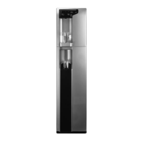
- Page 1 INSTALLATION & OPERATION GUIDE 818 SPORT MODELS...
- Page 2 Technical Manual 818 Sport Models Contents 1. Range Overview........Page 4 2.
- Page 3 Technical Manual 818 Sport Section1...
- Page 4 818 Sport Models Range Overview A range of compact countertop water dispensers, available in two different operational types: • 818 Cold and Ambient (Low Pressure Tank System) • 818 CS Cold and Sparkling (Direct Chill System) Both types are available as: •...
- Page 5 818 Sport Models All Types All B&O 818 Sport models are self contained machines with robust steel framed cabinets and attractively injection moulded plastic front, side and top panels. There is sufficient space internally for most filters to be fitted behind the right side panel.
- Page 6 818 Sport Models Controls Cold & Ambient Models On/Off switch – at upper rear of machine. Switches Cooling Operation on/off. Cold Thermostat – at rear of machine. Factory set to: NB: Turn clockwise to decrease water temperature Ambient Button Press to dispense Ambient water...
- Page 7 818 Sport Models Base Cabinet Either 818 model is designed to fit straight onto the top of the cabinet. Ensure the feet of the machine securely locate in the nesting positions. The Door Panel is hinged and fastened with Magnetic Catches. The Cabinet can be levelled using the adjustable feet.
-
Page 8: Specifications
818 Sport Models Specifications COOLING SYSTEM High efficiency compression system with capillary control. Premium quality long life hermetic compressor. Compact internal condenser – fan assisted for greater efficiency. Environmentally friendly R134A refrigerant. High volume 3.5 litre stainless steel pressurised cold tank for optimum water capacity on demand and hygiene. - Page 9 Technical Manual 818 Sport Section2...
- Page 10 818 Sport Models 818 Sport Cold and Ambient Model Operation Contents: • Major Components • Water Connection • Operation • Safety • Sanitisation Guide (See section 3)
-
Page 11: Major Components
818 Sport Models Major Components Top Cover Cold Water Tank Ambient Water Button Cold Water Button Control Panel Water Connection Inlet Water ( ”) Drain Port... - Page 12 818 Sport Models Operation 1. After connecting the water the tank will begin to fill. Put the plug in the socket and the indicator lights will be lit. Try pressing the cold water button to see if water comes out.
- Page 13 818 Sport Models 3. Press the ambient water button for ambient water. Cold Power Chilling System Indicator Indicator Cold Water Button Ambient Water Button 4. Press the cold water button for cold water.
- Page 14 818 Sport Models Safety Leave a space no less than 15cm between the wall and dispenser. Keep the machine away from sunlight, heat and moisture. Be sure to use single outlet socket with correct power voltage. Plug the power cord directly into the electrical...
- Page 15 818 Sport Models 818CS Cold and Sparkling Model Operation Contents: • Major Components • Water and CO Connection • Cold Water Operation • CO Bottle Installation • Sparkling Operation • Safety • Leak Detection • Sanitisation Guide (See Section 3)
- Page 16 818 Sport Models Major Components Top Cover Sparkling Water Tank Cold Water Tank Control Panel Water and CO Connection Connector ( ”) Inlet water ( ”) Drain Port...
- Page 17 818 Sport Models Cold Water Operation 1. After connecting the water the tank will begin to fill with water. Plug in the power and the indicator LEDs Cold water power will be on. Try pressing the cold button until the water comes out.
- Page 18 818 Sport Models Bottle Installation 1. Attach the regulator to the disposable CO bottle, ensuring the regulator is closed. 2. Connect the assembled CO bottle and regulator to the machine. Refill Tube 3. Do not open the regulator valve until the Carbonated switch has been turned on.
- Page 19 818 Sport Models Safety Leave a space no less than 15cm between the wall and dispenser. Keep the machine away from sunlight, heat and moisture. Be sure to use single outlet socket with correct power voltage. Plug the power cord directly into the electrical...
- Page 20 818 Sport Models Leak Detection Notice: This machine is equipped with a leakage detection device. When leaking is detected, the power will be cut off automatically. When the power has been cut off: 1. Unplug the machine, then remove the left side plate.
- Page 21 Technical Manual 818 Sport Section3...
- Page 22 818 Sport Models Sanitisation Guide – 818 CS Water Cooler 1. Turn off incoming mains water, briefly press dispense button(s) to release internal water pressure from the machine and remove filter. 2. Add 100 ml of a proprietary sanitisation fluid to a clean and empty service filter cartridge/dosing device and connect into machine.
- Page 23 818 Sport Models Sanitisation Guide – 818 Water Cooler 1. Turn off incoming mains water, briefly press dispense button(s) to release internal water pressure from the machine and remove filter. 2. Add 100 ml of a proprietary sanitisation fluid to a clean and empty service filter cartridge/dosing device and connect into machine.
- Page 24 Technical Manual 818 Sport Section4...
- Page 25 818 Sport Models 8 1 8 M O D E L S O N L Y Trouble Shooting Fault Diagnosis Guide 1 No Water Dispenses Problem/ Possible Cause Suggested Action Report No Water Dispenses From Ambient Water Supply turned off...
- Page 26 818 Sport Models 8 1 8 M O D E L S O N L Y Trouble Shooting Fault Diagnosis Guide 2 No Water Dispenses continued No Water Dispenses continued From Ambient Button not being pressed Press button firmly N.B. This could be...
- Page 27 818 Sport Models 8 1 8 M O D E L S O N L Y Trouble Shooting Fault Diagnosis Guide 3 Water Dispenses but Not Correct Temperature Problem/ Possible Cause Suggested Action Report Water Dispenses But Not Correct Temperature...
-
Page 28: Water Leaks
818 Sport Models 8 1 8 M O D E L S O N L Y Trouble Shooting Fault Diagnosis Guide 4 Water Leaks Problem/ Possible Cause Suggested Action Report Water Leaks Water lying on Overflowing Drip Empty Drip Tray top edge of Tray/Waste Container. - Page 29 Level up machine When installed with Base Cabinet. Missing Fixings. Replace missing fixings. Tripping out Machine in high humidity Discuss possible repositioning with Electricity environment. customer. supply Electrical circuitry faults. Test, identify and address accordingly. See Electrical Diagrams. (Contact Azure Technical Support for further advice).
- Page 30 Faulty PCB Replace PCB. From Ambient Fluctuating mains water Contact Azure Technical Support regarding or Cold Water pressure situation. special replacement washers available. Valve and hammering noise Continuous Water Dispense From Ambient Button jammed on/faulty.
- Page 31 Technical Manual 818 Sport Section5...
- Page 32 818 Sport Models Exploded Component Diagram 1 Borg & Overström Sport CW818 Cold & Ambient Exploded Component Diagram Model No-818...
- Page 33 818 Sport Models Exploded Component Diagram 2 Borg & Overström Sport CS818 Cold & Sparkling Exploded Component Diagram Model No-818...
-
Page 34: Parts Diagram
818 Sport Models Parts Diagram Borg & Overström Sport 828 Base Cabinet Parts Diagram Model No 828-01... - Page 35 818 Sport Models...
- Page 36 818 Sport Models...
- Page 37 818 Sport Models Water Pathway Diagram 1 Input Level Control Module Carbonated Water Tank Cold Tank Checking Water In Valve Low (Y) Bottom Plate Full (r) Common (B) Inlet Solenoid Valve Carbonated Water Solenoid Valve Faucet Cold Water Solenoid Valve...
- Page 38 818 Sport Models Water Pathway Diagram 2 Water In Vent Grit Filler Faucet Drainage Water Grit Filler Cold Solenoid Valve Borg & Overström CW818 Cold & Ambient Water Pathway Diagram (Series – 01) Azure UK...
- Page 39 Technical Manual 818 Sport Section6...
- Page 40 818 Sport Models Quantity Exploded component view reference Azure Part Azure Ref 818CS 818CW 123185 Top Panel Black 120815 Front Panel-Silver 126826 Keypad Panel - Black 124851 Bottom Panel - Black 125831 Drip Tray set 132449 Single check Valve 121055...
- Page 41 818 Sport Models Quantity Exploded component view reference Azure Part Azure Ref 818CS 818CW 134602 Copper Tubing 181342 4.0 x 20 YP PHD S/T Screw 174316 Dryer 134604 Copper Tubing 181128 3.5 x 18 BA RHD S/T Screw 181129 4.0 x 12 s/s RHD S/T Screw 171222 PCB-Cold &...
- Page 42 818 Sport Models Quantity Exploded component view reference Azure Part Azure Ref 818CS 818CW 174310 DC Tank Pump Set 131581 Thermostat Sleeve Cap 132448 Single Check Valve 181131 4.0 x 25 RHD S/T Screw 131643 " Stem Elbow 131652 " x 3/8" Male Thread Elbow...
- Page 43 818 Sport Models Quantity Exploded component view reference Azure Part Azure Ref 818CS 818CW 131581 Faucet Bung 131641 " Push fit inlet Connector 134565 Dispense Tube-Large 174312 PCB Rear Cover 194121 " Grit Filter 131649 " Push fit Tee 134592 "...
- Page 44 818 Sport Models Quantity Exploded component view reference Azure Part Azure Ref 818CS 818CW 184422 Top Bracket-Front 133424 Cold Tank Lid 134564 Dispense Tube 135732 Cold Tank Insulation -Top 135731 Cold Tank Insulation 133421 Cold Tank Coller 183423 Large Back Nut...
- Page 45 818 Sport Models Quantity Exploded component view reference Azure Part Azure Ref 818CS 818CW 184532 Adjustable Foot 184411 Grommet 182374 3.5 x 10 YP RHD S/D Screw Cabinet 193186 Level sensor (Complete) 131568 Drain Connector 184641 Drain Tube Fastener 134571...
- Page 46 Technical Manual 818 Sport Section7...
- Page 47 N.B. There should always be some variation between compressors. What should be identified is large discrepancies/unbalanced readings. Also, especially in the case of large discrepancies/unbalanced readings, check for continuity between any of the terminals and the compressor casing. A current will indicate a shorted winding (Contact Azure Technical support). 6. Checking the relays: Caution: Ensure the larger relay is discharged if recently energised.
- Page 48 Azure Technical Support). 3. Continue to follow the pipe work from the end of the condenser to the dryer. • A frozen / iced dryer will indicate a blockage (Contact Azure Technical Support) Again; a high current draw would confirm this.
- Page 49 818 Sport Models...
- Page 50 818 Sport Models...
- Page 51 Notes...
- Page 52 Notes...
- Page 53 Notes...
- Page 54 Notes...
- Page 55 INSTALLATION & OPERATION GUIDE 818 SPORT MODELS Technical Support Available 0700-1700 Monday to Friday Telephone 01362 656926 01362 656923 Email service@azureuk.co.uk Azure UK 5 John Goshawk Road Rash's Green East Dereham Norfolk NR19 1SY t +44 (0) 1362 656 928 f +44 (0) 1362 656 920 e sales@azureuk.co.uk...
Need help?
Do you have a question about the 818 and is the answer not in the manual?
Questions and answers
My unit is over filling from resorvor.
The Borg & Overstrom 818 unit may be overfilling from the reservoir due to faulty level sensors, a leak in the supply inlet pipe or filter, or a malfunction in the machine's water pipe work fittings. Checking and replacing the level sensors, locating and repairing any leaks, and ensuring proper pressure regulation with a pressure-reducing valve if needed can help resolve the issue.
This answer is automatically generated