Table of Contents
Advertisement
Quick Links
Advertisement
Table of Contents

Subscribe to Our Youtube Channel
Related Manuals for Videx VR4KGSM-1


Summary of Contents for Videx VR4KGSM-1
- Page 1 VR GSM AUDIO INTERCOM KIT 4000 Series Vandal Resistant GSM Audio Intercom with Proximity Facility GSMVRK GSMVRKC Technical Manual We recommend 66250675-EN This equipment is installed by a V1.0 - 05/09/17 Competent Electrician, Security or Communications Engineer.
-
Page 2: Declaration Of Conformity
Separate FCC approval for this product is not required as it will be classed as a fixed installation. THIS PRODUCT IS NOT DESIGNED TO BE USED AS AN EMERGENCY CALL POINT. MANUFACTURER CUSTOMER SUPPORT All Countries: VIDEX ELECTRONICS S.P.A. www.videx.it - technical@videx.it THE POWER TO SECURE Tel: +39 0734-631699 - Fax: +39 0734-632475 VIDEX ELECTRONICS S.P.A. -
Page 3: Table Of Contents
4000 Series Vandal Resistant GSM Audio Intercom with Proximity Facility Contents Introduction .......................................4 System Components and Available Versions ..........................6 Technical Information ..................................13 Additional Modules ..................................19 Wiring Diagrams ..................................... 23 Auxiliary Input & Output ................................26 USB Connection ....................................28 General Directions for Installation .............................. -
Page 4: Introduction
SIM CARD SELECTION A SIM card is required for this product but not supplied by Videx. The GSM intercom can only accept a standard size SIM card (refer to the following SIM card size chart on page 5), both a micro-SIM and nano-SIM are not suitable. It is recommended to choose the SIM card which has the best coverage for the area in which the intercom panel will be installed. - Page 5 We would recommend using a GSM signal strength meter (not supplied by Videx) to survey the intended antenna location. Contact Videx for more information on where to purchase a tester.
-
Page 6: System Components And Available Versions
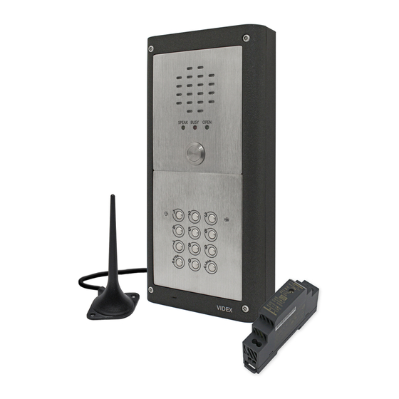
DESCRIPTION A system comprises of an intercom panel, power supply, SIM card (SIM card not provided by Videx) and antenna. The intercom panel is part of the Videx 4000 series vandal resistant modular design allowing it to be customised to the installation requirements for example including coded access or including the correct number of call buttons (up to 24 call buttons). - Page 7 BUTTON MODULE NOTES If the GSM module has 1 button (VR4KGSM-1), the additional button module buttons should be wired starting from button number 2 (i.e. the first button of the button module should be connected using the green “b” and white “1” wires, the next button using the blue “c”...
- Page 8 4000 Series Vandal Resistant GSM Audio Intercom with Proximity Facility System Components and Available Versions 4000 SERIES BACK BOXES AND MOUNTING FRAMES Both surface and flush back boxes and mounting frames are available. The size of the frame will depend on the number of modules that make up the GSMVRK/GSMVRKC kit.
-
Page 9: Art. 4884 Art
4000 Series Vandal Resistant GSM Audio Intercom with Proximity Facility System Components and Available Versions Surface Back Box Dimensions Part No. Housed Modules No. of Columns Back Box (W x H x D) mm Art.4881 135 x 160 x 43 Art.4882 135 x 280.2 x 43 Art.4883... - Page 10 Fig. 8 VANDAL RESISTANT GSM INTERCOM AUDIO KITS GSMVRK-1 - flush mounting 1 Outdoor station composed of: 1 GSM antenna 1 Power supply 1 Art. VR4KGSM-1: 1 button VR GSM unit Art. 432 DL-15-12 1 Art. 4851: Flush mounting box 12Vdc 1.25A GSMVRK-1S - surface mounting...
-
Page 11: Art.4852
4000 Series Vandal Resistant GSM Audio Intercom with Proximity Facility System Components and Available Versions GSMVRKC-1 - flush mounting 1 Outdoor station composed of: 1 GSM antenna 1 Power supply 1 Art. VR4KGSM-1: 1 button VR GSM unit Art. 432 DL-15-12 1 Art. VR4KCLM-1: VR4K series codelock 12Vdc 1.25A 1 Art. 4852:... -
Page 12: Art.4853
1 Art.VR4KGSM-0; 1 Art.VR4KBM-9; 1 Art.VR4KGSM-0; 1 Art.VR4KBM-9; GSMVRKC-9 GSMVRKC-9S 1 Art.VR4KCLM; 1 Art.4853 1 Art.VR4KCLM; 1 Art.4883 1 Art.VR4KGSM-1; 1 Art.VR4KBM-9; 1 Art.VR4KGSM-1; 1 Art.VR4KBM-9; GSMVRKC-10 GSMVRKC-10S 1 Art.VR4KCLM; 1 Art.4853 1 Art.VR4KCLM; 1 Art.4883 1 Art.VR4KGSM-2; 1 Art.VR4KBM-9;... -
Page 13: Technical Information
ART. VR4KGSM MODULE Button harness connection Speaker volume dip-switches Wiegand reader connection Antenna connection 103mm SIM card holder Art.150 GSM Unit for VR Panels VR4KGSM-0 VR4KGSM-1 VR4KGSM-2 VR4KGSM-3 Button Antenna Harness Wiegand UIM-138 SPEAK BUSY OPEN Terminal connections Micro USB Call progress LED’s... - Page 14 4000 Series Vandal Resistant GSM Audio Intercom with Proximity Facility Technical Information TERMINAL CONNECTIONS AND HARNESS CONNECTIONS Terminal Description Normally oclosed relay contact. Relay contacts: Normally open relay contact. 3A@24Vdc 3A@120Vac Common relay contact. Push to exit input (switched 0V). Auxiliary input (switched 0V).
- Page 15 4000 Series Vandal Resistant GSM Audio Intercom with Proximity Facility Technical Information TECHNICAL SPECIFICATION Working Voltage : 12Vdc +/- 10% Standby Current : approx. 60mA Max. Current : approx. 500mA (max.) Call Buttons : up to 24 (max.) Telephone Numbers per Button : 4 telephone numbers (1 primary, 3 diverts) Dial to Open Numbers : up to 1000 (max.)
- Page 16 4000 Series Vandal Resistant GSM Audio Intercom with Proximity Facility Technical Information TERMINAL CONNECTIONS Connection Description 12-24V AC or DC power input 0V power input Relay 1 common connection Relay 1 normally open connection Relay 1 normally closed connection Relay contacts: 3A@24Vac/dc Relay 2 common connection Relay 2 normally open connection...
- Page 17 4000 Series Vandal Resistant GSM Audio Intercom with Proximity Facility Technical Information ART. VR4KCLM-1 PROGRAMMING GUIDE Initial Programming All programming is carried out using the keypad. The programming menu is protected by an engineer’s code. The factory default engineer’s code is ‘111111’ (6x1). This code can be changed to any 4 to 6 digit engineer’s code during the programming, but must be different to the access codes used to gain entry.
- Page 18 4000 Series Vandal Resistant GSM Audio Intercom with Proximity Facility Technical Information Re-programming the Codelock If the VR4KCLM-1 codelock has been programmed with an existing access code and it needs to be changed then follow the flow chart below to re-program a new acces code: Enter the existing engineer’s code.
-
Page 19: Additional Modules
4000 Series Vandal Resistant GSM Audio Intercom with Proximity Facility Additional Modules As previously mentioned on page 14 additional modules can be connected to the vandal resistant GSM intercom: • a display interface module the VR4KDM; • an off-board Wiegand proximity reader the VR4KPPM (XPROX). ART. - Page 20 USB cable input. Antenna Art.150 GSM Unit for VR Panels Art. VR4KDM UIM-138 Made in Italy User information module UIM138 1.3 - UIM138 SP10 VR4KGSM-0 VR4KGSM-1 VR4KGSM-2 VR4KGSM-3 Down High 0V A0 I1 I2 I3 I4 I5 Button Antenna Harness Wiegand UIM-138...
- Page 21 4000 Series Vandal Resistant GSM Audio Intercom with Proximity Facility Additional Modules ART. VR4KPPM (WIEGAND PROXIMITY READER) The VR4KPPM Wiegand proximity reader (as shown in Fig.16) can be connected to the GSM module using the ‘plug-in’ proximity connection harness. Further information on programming proximity fobs/cards can be found on pages 46 and 47 of this manual. 103mm Art.
- Page 22 (data) D0/CLOCK/DATA white wire (data). black wire (0V). red wire linked across to terminals 3 and 1 (+positive). Antenna Art.150 GSM Unit for VR Panels Art. VR4KPPM (XPROX) VR4KGSM-0 VR4KGSM-1 VR4KGSM-2 VR4KGSM-3 Button Antenna D1/DATA Harness Wiegand D0/CLOCK/DATA UIM-138 orange...
-
Page 23: Wiring Diagrams
4000 Series Vandal Resistant GSM Audio Intercom with Proximity Facility Wiring Diagrams GSMVRK CONNECTIONS Fig.18 shows the wiring connections for a GSMVRK-1 / GSMVRK-1S audio kit. Art.150 GSM Unit for VR Panels VR4KGSM-0 VR4KGSM-1 VR4KGSM-2 VR4KGSM-3 Button Antenna Harness Wiegand... - Page 24 If the GSM intercom is going to be connected to an electric gate then the wires from the gate controls can be connected directly into the CO and NO relay terminals on the GSM module. Follow the connections shown in Fig.20. Art.150 GSM Unit for VR Panels VR4KGSM-0 VR4KGSM-1 VR4KGSM-2 VR4KGSM-3 Button Antenna...
- Page 25 When the programmed timeband is reached on the timeclock pressing the trade button will trigger the GSM module’s push to exit (PTE) input and the GSM relay will trigger for the programmed time, RLT. Art.150 GSM Unit for VR Panels VR4KGSM-0 VR4KGSM-1 VR4KGSM-2 VR4KGSM-3 Button Antenna...
-
Page 26: Auxiliary Input & Output
Fig.23 below shows the connection for auxiliary output AO when the A1M mode is set to 00. The auxiliary output AO will activate once a call to an apartment has been made and will stay activated for the duration of the call. Art.150 GSM Unit for VR Panels VR4KGSM-0 VR4KGSM-1 VR4KGSM-2 VR4KGSM-3 Button Antenna... - Page 27 Fig.25 below shows the connection for auxiliary output AO when the A1M mode is set to 02. The auxiliary output AO will activate once a call to an apartment has been made and will stay activated for the programmed auxiliary output time A1T. Art.150 GSM Unit for VR Panels VR4KGSM-0 VR4KGSM-1 VR4KGSM-2 VR4KGSM-3 Button Antenna...
-
Page 28: Usb Connection
GSMSK-66251720-EN-V1-3 (or later version). USB CONNECTION The GSM module can be connected using a standard micro-USB to USB cable as shown in Fig.27. Art.150 GSM Unit for VR Panels VR4KGSM-0 VR4KGSM-1 VR4KGSM-2 VR4KGSM-3 Button Antenna Harness... -
Page 29: General Directions For Installation
Videx DO NOT recommend these types of cable. GENERAL INSTALLATION NOTES •... - Page 30 CONNECTION TO MAINS, SAFETY AND GUIDANCE NOTES IMPORTANT: PLEASE READ THESE INSTRUCTIONS CAREFULLY BEFORE COMMENCING WITH THE INSTALLATION. Videx recommends that any cabling and Videx product be installed by a competent and qualified electrician, security installation speclialist or communications engineer.
- Page 31 4000 Series Vandal Resistant GSM Audio Intercom with Proximity Facility General Directions for Installation Fig. 31 Fig. 32 Fig. 33 PANEL CARE The digital GSM panel facia is brushed stainless steel. It is important that the facia is cleaned on regular occasions to prevent dirt build up and tarnishing of the metal.
-
Page 32: Fitting The Sim & Connecting Power
4000 Series Vandal Resistant GSM Audio Intercom with Proximity Facility Fitting the SIM & Connecting Power FITTING THE SIM CARD AND CONNECTING THE POWER TO THE GSM INTERCOM After connecting the power supply, antenna, lock output and any auxiliary devices as shown in this manual and before powering up, a SIM card must be installed (the SIM must already be registered with the network provider). -
Page 33: Reset Procedure
4000 Series Vandal Resistant GSM Audio Intercom with Proximity Facility Reset Procedure RESETTING THE GSM MODULE TO FACTORY DEFAULTS There are two reset options for the GSM module. The first will reset the master code only and the second will reset everything and clear all stored telephone numbers, proximity cards and settings. -
Page 34: 4000 Series Back Box Installation
4000 Series Vandal Resistant GSM Audio Intercom with Proximity Facility 4000 Series Back Box Installation EXAMPLE: INSTALLING A 4000 SERIES TWO MODULE SURFACE BACK BOX (ART. 4882) Fig. 47 Fig. 48 Fig. 49 Fig. 50 Fig. 51 Fig. 52 Fig. 53 Fig. - Page 35 4000 Series Vandal Resistant GSM Audio Intercom with Proximity Facility 4000 Series Back Box Installation INSTALLING A SURFACE MOUNT DOOR STATION 1. Place the surface box against the wall (165-170cm between the top of the box and the floor level as shown in Fig.47) and mark the fixing holes for the wall plugs and the hole for the cables...
- Page 36 4000 Series Vandal Resistant GSM Audio Intercom with Proximity Facility 4000 Series Back Box Installation EXAMPLE: INSTALLING A 4000 SERIES TWO MODULE FLUSH BACK BOX (ART. 4852) Fig. 59 Fig. 60 Fig. 61 Fig. 62 Fig. 63 Fig. 64 Fig. 65 Fig.
- Page 37 4000 Series Vandal Resistant GSM Audio Intercom with Proximity Facility 4000 Series Back Box Installation INSTALLING A FLUSH MOUNTING DOOR STATION 1. It is recommended that the flush box is mounted into the wall approximately 165-170cm between the top of the box and the floor level as shown in Fig.59.
-
Page 38: Programming The Gsm Intercom
4000 Series Vandal Resistant GSM Audio Intercom with Proximity Facility Programming the GSM Intercom PROGRAMMING THE GSM INTERCOM Programming the GSM intercom can be carried out in two ways, either by sending text (SMS) messages or by using the GSMSK PC software (ver 3.1.0.10 or later), also refer to the programming manual GSMSK-66251720-EN-V1-3 (or later). - Page 39 4000 Series Vandal Resistant GSM Audio Intercom with Proximity Facility Programming the GSM Intercom Send DTMF tone delay 1111DTTnn nn = 01 - 12 44 - 45 Enable dial 0 on answer function EDZ 1111EDZnn? nn = 00 or 01 Enable # (hash) function 1111ED#nn? nn = 00 or 01...
- Page 40 4000 Series Vandal Resistant GSM Audio Intercom with Proximity Facility Programming the GSM Intercom STORING A TELEPHONE NUMBER FOR DIAL IN DOOR RELEASE (STR) Dial in door release allows users to release the door/gate simply by dialling the telephone number of the SIM in the GSM intercom panel.
- Page 41 4000 Series Vandal Resistant GSM Audio Intercom with Proximity Facility Programming the GSM Intercom SET AUXILIARY OUTPUT AO MODE (A1M, MODES 00 - 02) The auxiliary output AO has up to 3 modes that can be set: Call Activated (on during a call): nn = 00 AO output will activate when a call begins and deactivate when a call ends.
- Page 42 IMPORTANT NOTE: Videx are only aware of the balance check dial string codes for the network providers mentioned above. Check dial string codes for other networks are currently unavailable at this time. Please also note that this programming function is only applicable for pay as you go SIM cards.
- Page 43 4000 Series Vandal Resistant GSM Audio Intercom with Proximity Facility Programming the GSM Intercom 1111BAL? Check current balance of the SIM in the GSM intercom and send a confirmation text back to the sender. In addition to this feature the GSM intercom also has the facility to monitor the available credit and then text the user to inform them when the credit has fallen below £5.00, €5.00 or $5.00.
- Page 44 The GSM intercom will reply with the following text: CLK = 16/04/18, 10.05 VIDEX GSM SILENT DIALLING MODE (AUE) When the GSM intercom is calling the telephone number stored there is a choice of either hearing the ringing tone from the intercom panel or just hearing beeps to indicate a call is in progress.
- Page 45 4000 Series Vandal Resistant GSM Audio Intercom with Proximity Facility Programming the GSM Intercom • The DTP command sets the DTMF tone required (from 0 - 9) after a call is answered for button 1. • The DTD command sets the DTMF tone required (from 0 - 9) after divert 1 call is answered for button 1. •...
- Page 46 • 955/T or 955/C = Videx fobs or cards. These fobs and cards have no site code and have a 5 digit user code, so the PBY function must be set to 02 (the default setting, checking for 2 bytes).
- Page 47 The GSM intercom will reply with the following text: STORED IN nnn VIDEX GSM (where nnn = the dial to open location of where the number is stored). Example 2: Find dial to open location of the telephone number using the last 4 digits of the number 4567, the following text can be sent to the GSM intercom: 1111FDT”4567”?
- Page 48 For the application of these commands please contact Videx Technical on tel: 0191 224 3174. For overseas customers please contact Videx customer support on tel: (+39) 0734 631 699.
-
Page 49: System Operation
4000 Series Vandal Resistant GSM Audio Intercom with Proximity Facility System Operation MAKING A CALL AND ANSWERING A CALL FROM THE GSM INTERCOM When the system is in standby all the LED’s (speak, busy and open) on the front of the GSM intercom will be switched OFF, as SPEAK BUSY OPEN SPEAK BUSY OPEN... - Page 50 4000 Series Vandal Resistant GSM Audio Intercom with Proximity Facility System Operation USING A PROXIMITY READER (ONLY APPLICABLE IF AN ART.VR4KPPM READER IS CONNECTED) In order for the Art.VR4KPPM proximity reader to work correctly it must first be connected to the GSM intercom using the 'plug-in' proximity harness as shown in Fig.17 on page 22 and the proximity reader enabled (also refer to enable proximity reader EPR notes and proximity bytes PBY notes on page 46 for correct setup).
-
Page 51: User Commands
4000 Series Vandal Resistant GSM Audio Intercom with Proximity Facility User Commands USER COMMAND TABLES The following user command table shows the user commands that can be carried out during a call. Successful commands are signalled by two beeps from the telephone, errors are signalled by four beeps. IMPORTANT NOTE: When the ED# function has been enabled the user must press the # button on their phone before pressing any of the following user commands (also refer to page 45 for further information). -
Page 52: Additional User Information
The example below shows the reply to expect from the GSM intercom: SIGNAL = 31 BER = 0 OK VIDEX GSM DIALLING INTO THE GSM INTERCOM FROM ANOTHER TELEPHONE There are three possible outcomes to dialling into the GSM intercom depending on the telephone number you are dialling in from and the features setup during programming. - Page 53 4000 Series Vandal Resistant GSM Audio Intercom with Proximity Facility Additional User Information UNDERSTANDING THE BEEPS Functions and errors are indicated by beeps from the GSM intercom panel. The following will help you understand the different beeps heard and what, if anything, needs to be done in response to the beeps. BEEP REASON SOLUTION...
-
Page 54: User Management
4000 Series Vandal Resistant GSM Audio Intercom with Proximity Facility User Management RECORD SHEET In order to manage the GSM intercom effectively it is recommended that an up to date record sheet is kept for all the programming particularly if there is a high volume of telephone numbers and fob/cards stored in the GSM intercom. This will also be useful if any future changes need to be made. -
Page 55: Troubleshooting
UNICODE and is set to either GSM alphabet or Automatic. This can ususally be done via etc. the settings icon on the smartphone. If you are unsure of how to do this Videx recommend consulting with the user’s manual that came with the smartphone or consulting directly with the manufacturer of the smartphone. - Page 56 3. After the GSM intercom has rebooted test the door opening feature from the telephone during a call. If neither of the above solutions resolve the problem then please contact Videx technical on tel: 0191 224 3174 for further assistance. For overseas customers contact Videx customer support on tel: (+39) 0734 631 699 for further assistance.
-
Page 57: General Information
4000 Series Vandal Resistant GSM Audio Intercom with Proximity Facility General Information SOFTWARE REVISION DATE SOFTWARE VERSION REVISION 11/09/17 VR3.0.0 (2G) , VR3.1.0 (3G) Launch of Vandal Resistant GSM (Art.150) series. FURTHER READING Additional programming information using the GSMSK PC software can be found in the following technical manual: •... -
Page 58: Notes
4000 Series Vandal Resistant GSM Audio Intercom with Proximity Facility Notes 4000 Series Vandal Resistant GSM - Technical Manual 66250675-EN - V1.0 - 05/09/17... - Page 59 4000 Series Vandal Resistant GSM Audio Intercom with Proximity Facility Notes 4000 Series Vandal Resistant GSM - Technical Manual 66250675-EN - V1.0 - 05/09/17...
- Page 60 THE POWER TO SECURE MANUFACTURER CUSTOMER SUPPORT VIDEX ELECTRONICS S.P.A. All Countries: Via del Lavoro, 1 - 63846 Monte Giberto (FM) Italy VIDEX ELECTRONICS S.P.A. Tel (+39) 0734 631669 - Fax (+39) 0734 632475 www.videx.it - technical@videx.it www.videx.it - info@videx.it...
Need help?
Do you have a question about the VR4KGSM-1 and is the answer not in the manual?
Questions and answers