Videx 4000 Series Technical Manual
Vandal resistant gsm audio intercom with proximity facility
Hide thumbs
Also See for 4000 Series:
- Technical manual (80 pages) ,
- Installation instructions manual (44 pages) ,
- Instruction manual (40 pages)
Table of Contents
Advertisement
Advertisement
Table of Contents

Related Manuals for Videx 4000 Series


Summary of Contents for Videx 4000 Series
- Page 1 VR GSM AUDIO INTERCOM KIT 4000 Series Vandal Resistant GSM Audio Intercom with Proximity Facility GSMVRK GSMVRKC Technical Manual We recommend 66250675-EN This equipment is installed by a V2.1 - 07/11/19 Competent Electrician, Security or Communications Engineer.
- Page 2 4000 Series Vandal Resistant GSM Audio Intercom with Proximity Facility Declaration of Conformity EU RoHS DECLARATION OF CONFORMITY 2G version Telit Communications certi es that the GL865-QUAD V3 (Quad Band GSM850/EGSM900/DCS1800/PCS1900 GPRS Wireless Module) is in conformity with Directive 2011/65/EU of the European Parliament and the Council of 8th June 2011 on the restriction of the use of certain hazardous substances in electrical and electronic equipment.
-
Page 3: Table Of Contents
4000 Series Vandal Resistant GSM Audio Intercom with Proximity Facility Contents Introduction .......................................4 System Components and Available Versions ..........................6 Art. VR4KGSM Technical Information............................13 Art. VR4901 Technical Information ............................... 15 Additional Modules - Art. VR4KDM .............................. 18 Additional Modules - Art. VR4KPPM ............................. 20 Wiring Diagrams ..................................... -
Page 4: Introduction
SYSTEM INTRODUCTION The 4000 series vandal resistant GSM is designed to work on the same technology as mobile phones. It enables a call to be made from an entry point (door, gate etc), to any telephone number (mobile or land line). Up to 24 users can be programmed into the door panel, each able to call up to four telephone numbers (if the primary number is busy or not answered, the call can be diverted through to up to three di erent divert numbers). - Page 5 Network provider and services con guration codes mentioned in this manual are speci c for the UK. For overseas customers please contact the network provider of your country for the corresponding codes, however Videx o ers no guarantee that any additional codes will work.
-
Page 6: System Components And Available Versions
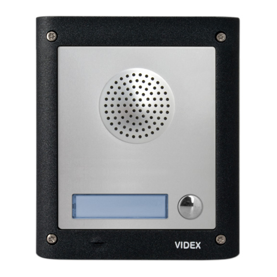
ART. VR4KGSM ART. 150 INTERCOM AVAILABLE VERSIONS The intercom panel can include any of the modules from the 4000 series vandal resistant range and uses the standard 4000 series surface and ush mounting frames. The GSM module is however essential and includes all the GSM communication electronics, SIM card (supplied separately) and connections. - Page 7 4000 Series Vandal Resistant GSM Audio Intercom with Proximity Facility System Components and Available Versions BUTTON HARNESS WIRING 6 a b c d button harness connector 5 1 2 3 4 white wire red wire brown wire black wire grey wire...
- Page 8 Fig.4 ( ush) and Fig.5 (surface) with the following tables showing the back box dimensions including the part numbers and dimensions for optional ush and surface 4000 series rainshields. Flush Back Boxes and Mounting Frames Art.
- Page 9 4000 Series Vandal Resistant GSM Audio Intercom with Proximity Facility System Components and Available Versions continued Art.4884 270 x 280.2 x 43 Art.4886 270 x 400.4 x 43 405 x 400.4 x 43 Art.4889 Part No. Module Size Rainshield Dimensions (W x H x D) mm 140 x 163 x 62 Art.4891...
- Page 10 4000 Series Vandal Resistant GSM Audio Intercom with Proximity Facility System Components and Available Versions ART. VR4901 CODELOCK The VR4901 codelock module (included as part of the GSMVRKC kits), see Fig.8, can be powered from 12-24V AC or DC and includes three dry contact relay outputs and two switched 0V push to exit inputs which can be used to trigger relay 1 &...
- Page 11 4000 Series Vandal Resistant GSM Audio Intercom with Proximity Facility System Components and Available Versions GSMVRKC-1 - ush mounting 1 Outdoor station composed of: 1 GSM antenna 1 Power supply 1 Art. VR4KGSM-1: 1 button VR GSM unit Art. 432 HDR-15-12 1 Art. VR4901:...
- Page 12 4000 Series Vandal Resistant GSM Audio Intercom with Proximity Facility System Components and Available Versions Kit No. Outdoor station composed of: Kit No. Outdoor station composed of: GSMVRKC-3 1 Art.VR4KGSM-3; 1 Art.VR4901; 1 Art.4852 GSMVRKC-3S 1 Art.VR4KGSM-3; 1 Art.VR4901; 1 Art.4882 1 Art.VR4KGSM-0;...
-
Page 13: Art. Vr4Kgsm Technical Information
4000 Series Vandal Resistant GSM Audio Intercom with Proximity Facility Art. VR4KGSM Technical Information ART. VR4KGSM 150 MODULE 103mm SPEAK BUSY OPEN Fig. 9 Front Fig. 10 Back SPEAKER VOLUME ADJUSTMENT DIP SWITCH SETTINGS LEGEND There are 2 dip-switches located on the back of the VR4KGSM module under Intercom speaker the SIM card holder (Fig.10,... - Page 14 4000 Series Vandal Resistant GSM Audio Intercom with Proximity Facility Art. VR4KGSM Technical Information USB CONNECTION CN1 The micro-USB connection allows the VR4KGSM module to be connected to a laptop/PC for ease of programming (refer to page 27 for connecting the GSM module to a laptop/PC). Further information on programming using the GSMSK PC software can be found in the following manual GSMSK_66251720_EN_V2-0 (or later).
-
Page 15: Art. Vr4901 Technical Information
4000 Series Vandal Resistant GSM Audio Intercom with Proximity Facility Art. VR4901 Technical Information ART. VR4901 CODELOCK MODULE 103mm VR4901 Note: Remove MOV jumper completely when using a relay to trigger a gate controller. Fig. 11 DESCRIPTION LEGEND The codelock module, Fig.11, features 12 stainless steel buttons, backlit in blue... - Page 16 4000 Series Vandal Resistant GSM Audio Intercom with Proximity Facility Art. VR4901 Technical Information BACK LIGHT ADJUSTMENT JUMPER JPL The jumper JPL (Fig.11, ) is used to adjust the brightness and determine the operation of the backlit buttons. There are four brightness settings for the backlit buttons and two programming modes (mode 1 and 2) for the jumper.
- Page 17 4000 Series Vandal Resistant GSM Audio Intercom with Proximity Facility Art. VR4901 Technical Information PROGRAMMING GUIDE Press 1 six times ENTER THE • Enter the ENGINEER’S CODE: rst time type six times 1 (111111 “111111” “ENGINEER’S CODE” (factory default) factory default) and press ENTER(the red LED will illuminate);...
-
Page 18: Additional Modules - Art. Vr4Kdm
4000 Series Vandal Resistant GSM Audio Intercom with Proximity Facility Additional Modules - Art. VR4KDM ART. VR4KDM DISPLAY INTERFACE MODULE 103mm Art. VR4KDM UIM-138 Made in Italy User information module UIM138 1.3 - UIM138 SP10 Down High 0V A0 I1 I2 I3 I4 I5 Fig. - Page 19 4000 Series Vandal Resistant GSM Audio Intercom with Proximity Facility Additional Modules - Art. VR4KDM TERMINAL CONNECTIONS, HARNESS CONNECTIONS AND USB INPUT Terminal Description Switched 0V input. Programmable auxiliary output (switched 0V). 5 programmable auxiliary inputs. To program these inputs please refer to the technical manual: UIM-138 Display Module Manual - Technical Manual Edition 1.0...
-
Page 20: Additional Modules - Art. Vr4Kppm
4000 Series Vandal Resistant GSM Audio Intercom with Proximity Facility Additional Modules - Art. VR4KPPM ART. VR4KPPM WIEGAND PROXIMITY READER 103mm Art. VR4KPPM (XPROX) D1/DATA D0/CLOCK/DATA Fig. 18 Front Fig. 19 Back DESCRIPTION LEGEND As mentioned previously on page 14, the VR4KPPM Wiegand proximity reader Proximity reading area (shown in Fig.18 and Fig.19) can be connected to the GSM module using the... - Page 21 4000 Series Vandal Resistant GSM Audio Intercom with Proximity Facility Additional Modules - Art. VR4KPPM CONNECTING THE VR4KPPM TO THE GSM INTERCOM Follow the connections as shown in Fig.20 to connect the VR4KPPM Wiegand proximity module to the GSM intercom when using the ‘plug-in’...
-
Page 22: Wiring Diagrams
4000 Series Vandal Resistant GSM Audio Intercom with Proximity Facility Wiring Diagrams GSMVRK CONNECTIONS Fig.21 shows the wiring connections for a 12Vdc fail secure lock release through the relay of the GSMVRK-1 / GSMVRK-1S audio kit. Antenna FAIL SECURE LOCK RELEASE Fig. - Page 23 4000 Series Vandal Resistant GSM Audio Intercom with Proximity Facility Wiring Diagrams CONNECTING TO A GATE CONTROLLER If the GSM intercom is going to be connected to an electric gate then the wires from the gate controls can be connected directly into the CO and NO relay terminals on the GSM module.
- Page 24 4000 Series Vandal Resistant GSM Audio Intercom with Proximity Facility Wiring Diagrams CONNECTING A TRADE BUTTON USING AN ART. 701T 28G TIMECLOCK If required a digital timeclock, the Art.701T, can be used for connecting a trade button. First isolate a button either on the VR4KGSM module or VR4K button module (see button module variations in Fig.1 and Fig.2 on page 6).
-
Page 25: Auxiliary Input & Output
4000 Series Vandal Resistant GSM Audio Intercom with Proximity Facility Auxiliary Input & Output The GSM’s auxiliary output can be programmed to 3 di erent modes (00 - 02), please refer to programming notes on how to setup the auxiliary output mode (A1M) on page 43. - Page 26 4000 Series Vandal Resistant GSM Audio Intercom with Proximity Facility Auxiliary Input & Output AUXILIARY OUTPUT AO WHEN SET TO MODE 02 CALL ACTIVATED Fig.28 below shows the connection for auxiliary output AO when the A1M mode is set to 02. The auxiliary output AO will activate once a call to an apartment has been made and will stay activated for the programmed auxiliary output time A1T.
-
Page 27: Usb Connection
4000 Series Vandal Resistant GSM Audio Intercom with Proximity Facility USB Connection CONNECTIONS TO A PC The vandal resistant GSM intercom also includes a micro-USB connection allowing the module to be connected to a laptop/ PC for ease of programming and for downloading the event log. Programming is carried out using the GSMSK PC software. All programming features described in this manual are also accessible using the software. -
Page 28: General Directions For Installation
Videx DO NOT recommend these types of cable. GENERAL INSTALLATION NOTES •... - Page 29 IMPORTANT: IT IS RECOMMENDED THAT ANY CABLING AND VIDEX PRODUCTS BE INSTALLED BY A COMPETENT AND QUALIFIED ELECTRICIAN, SECURITY INSTALLATION SPECIALIST OR COMMUNICATIONS ENGINEER. • DO NOT install any Videx product in areas where the following may be present or occur: • Excessive oil or a grease laden atmosphere.
- Page 30 4000 Series Vandal Resistant GSM Audio Intercom with Proximity Facility General Directions for Installation PANEL CARE The GSM intercom’s facia is manufactured from brushed stainless steel. It is important that the it is cleaned on regular occasions to prevent dirt build up and tarnishing of the metal.
-
Page 31: Fitting The Sim & Connecting Power
4000 Series Vandal Resistant GSM Audio Intercom with Proximity Facility Fitting the SIM & Connecting Power FITTING THE SIM CARD AND CONNECTING THE POWER TO THE GSM INTERCOM After connecting the power supply, antenna, lock output and any auxiliary devices as shown in this manual and before powering up, a SIM card must be installed (the SIM must already be registered with the network provider). -
Page 32: Reset Procedure
4000 Series Vandal Resistant GSM Audio Intercom with Proximity Facility Reset Procedure RESETTING THE GSM MODULE TO FACTORY DEFAULTS There are two reset options for the GSM module. The rst will reset the master code only and the second will reset everything and clear all stored telephone numbers, proximity cards and settings. -
Page 33: 4000 Series Back Box Installation
4000 Series Vandal Resistant GSM Audio Intercom with Proximity Facility 4000 Series Back Box Installation EXAMPLE: INSTALLING A 4000 SERIES TWO MODULE SURFACE BACK BOX ART. 4882 Fig. 51 Fig. 52 Fig. 53 Fig. 54 Fig. 55 Fig. 56 Fig. 57 Fig. - Page 34 4000 Series Vandal Resistant GSM Audio Intercom with Proximity Facility 4000 Series Back Box Installation INSTALLING A SURFACE MOUNT DOOR STATION 1. Place the surface box against the wall (165-170cm between the top of the box and the oor level as shown in Fig.51) and mark (Fig.52).
- Page 35 4000 Series Vandal Resistant GSM Audio Intercom with Proximity Facility 4000 Series Back Box Installation EXAMPLE: INSTALLING A 4000 SERIES TWO MODULE FLUSH BACK BOX ART. 4852 Fig. 63 Fig. 64 Fig. 65 Fig. 66 Fig. 67 Fig. 68 Fig. 69 Fig.
- Page 36 4000 Series Vandal Resistant GSM Audio Intercom with Proximity Facility 4000 Series Back Box Installation INSTALLING A FLUSH MOUNTING DOOR STATION 1. It is recommended that the ush box is mounted into the wall approximately 165-170cm between the top of the box and the oor level as shown in Fig.63.
-
Page 37: Programming The Gsm Intercom
4000 Series Vandal Resistant GSM Audio Intercom with Proximity Facility Programming the GSM Intercom PROGRAMMING THE GSM INTERCOM Programming the GSM intercom can be carried out in two ways, either by sending text (SMS) messages or by using the GSMSK PC software (ver 4.0.0.0 or later), also refer to the programming manual GSMSK_66251720_EN_V2-0 (or later). - Page 38 4000 Series Vandal Resistant GSM Audio Intercom with Proximity Facility Programming the GSM Intercom Unlatch the relay 1111RUL Latch the auxiliary output AO 1111A1L Unlatch the auxiliary output AO 1111A1U Store timeband for call buttons 1111TBA”HHMMHHMM”,days HHMMHHMM 00002359 45 - 46...
- Page 39 4000 Series Vandal Resistant GSM Audio Intercom with Proximity Facility Programming the GSM Intercom Initiate a special command 1111PRG(command) AT commands AT command to send at start up AT1 1111AT1”ATxxxxxx”? Any AT command AT command to send at start up AT2 1111AT2”ATxxxxxx”?
- Page 40 4000 Series Vandal Resistant GSM Audio Intercom with Proximity Facility Programming the GSM Intercom 1111STNnnn”pn” (or 1111STNnnn”yyyyyyyyyyy”) Store the primary number and respective divert numbers in position nnn, (where pn = primary number, d1= 1st divert, d2 = 2nd divert, d3 = 3rd divert 1111STNnnn”pn”,”d1”...
- Page 41 4000 Series Vandal Resistant GSM Audio Intercom with Proximity Facility Programming the GSM Intercom Store the dial to open numbers (DTO) to the next available memory location(s), 1111STR”n1” ? where n1 = 1st DTO number, n2 = 2nd DTO number, n3 = 3rd DTO number, n4 1111STR”n1”,”n2”?
- Page 42 4000 Series Vandal Resistant GSM Audio Intercom with Proximity Facility Programming the GSM Intercom 1111STR004”01912243174”,”01912241558”,”07771234567”? The GSM will reply with the following text: MEM OPEN 004 = 01912243174 MEM OPEN 005 = 01912241558 MEM OPEN 006 = 07771234567 OK VIDEX GSM...
- Page 43 4000 Series Vandal Resistant GSM Audio Intercom with Proximity Facility Programming the GSM Intercom SET AUXILIARY OUTPUT AO MODE A1M, MODES 00 02 The auxiliary output AO has up to 3 modes that can be set: Call Activated (on during a call): nn = 00 AO output will activate when a call begins and deactivate when a call ends.
- Page 44 IMPORTANT NOTE: Videx are only aware of the balance check dial string codes for the network providers mentioned above. Check dial string codes for other networks are currently unavailable at this time. Please also note that this programming function is only applicable for pay as you go SIM cards.
- Page 45 4000 Series Vandal Resistant GSM Audio Intercom with Proximity Facility Programming the GSM Intercom To use this feature, the following settings must rst be made: 1. A Pay As You Go SIM card from a provider that o ers this service (Vodafone, O2) must be used.
- Page 46 4000 Series Vandal Resistant GSM Audio Intercom with Proximity Facility Programming the GSM Intercom Days Mo = Monday Tu = Tuesday We = Wednesday Th = Thursday Fr = Friday Sa = Saturday Su = Sunday AD = All days...
- Page 47 4000 Series Vandal Resistant GSM Audio Intercom with Proximity Facility Programming the GSM Intercom Example 1: To set timeband 0 to allow for proximity fobs/cards and/or dial to open numbers to be active between 8:00am in the morning up until 2:00pm in the afternoon and for weekends only, the following text can be sent to the GSM intercom, remembering to use 24hr clock notation: 1111ATB0”08001400”,WE?
- Page 48 4000 Series Vandal Resistant GSM Audio Intercom with Proximity Facility Programming the GSM Intercom AL8 = “1010101010” OK VIDEX GSM Remember that each timeband would be programmed using the store timeband command ATB (see previous pages). USING ACCESS LEVELS WITH DIAL TO OPEN NUMBERS STR Access levels can be assigned to dial to open numbers using the STR programming command.
- Page 49 4000 Series Vandal Resistant GSM Audio Intercom with Proximity Facility Programming the GSM Intercom The following text messages can be sent to the GSM intercom to enable (00), disable (01) or query the setting of the silent dialling feature. By default this feature is disabled i.e. set to 01, a ringing tone will be heard whilst dialling the number.
- Page 50 • 955/T or 955/C = Videx fobs or cards. These fobs and cards have no site code and have a 5 digit user code, so the PBY function must be set to 02 (the default setting, checking for 2 bytes).
- Page 51 4000 Series Vandal Resistant GSM Audio Intercom with Proximity Facility Programming the GSM Intercom The following texts can be used to program fobs or cards. 1111FOBnnn”site”,”user” Store fob/card in location nnn, where nnn = the memory location from 000 - 999 of where the fob/card is actually stored (see examples below for each type of fob/card).
- Page 52 4000 Series Vandal Resistant GSM Audio Intercom with Proximity Facility Programming the GSM Intercom FOB 097 = 0024115432,A3 OK VIDEX GSM FIND A FOB OR CARD FDF The nd a fob or card feature allows the user to search and nd the fob/card location (between 000 - 999) of where a proximity fob or card is stored in the GSM intercom.
- Page 53 4000 Series Vandal Resistant GSM Audio Intercom with Proximity Facility Programming the GSM Intercom Example: To program free access timeband number 7 to latch the GSM’s relay between 7:45am until 10:45am for the weekend only, the following text can be sent to the GSM intercom: 1111FRE7”07451045”WE:L:RL?
- Page 54 For the application of these commands please contact Videx Technical on tel: 0191 224 3174. For overseas customers please contact Videx customer support on tel: (+39) 0734 631 699.
- Page 55 4000 Series Vandal Resistant GSM Audio Intercom with Proximity Facility Programming the GSM Intercom In the example the extended output time for the GSM’s relay has been enabled. Since the original relay time RLT has been set to 05, when it is triggered the relay will activate for 5 minutes instead of 5 seconds. As code 81 was used the auxiliary output AO will still only operate in seconds i.e.
-
Page 56: The Gsm Mobile App
In addition to programming by direct text messages or using the GSMSK programming software it is also possible to program the GSM intercom using the GSM mobile app, the Videx SMS Wizard. The SMS wizard can be used to simplify the programming of the GSM intercom using SMS messages. -
Page 57: System Operation
4000 Series Vandal Resistant GSM Audio Intercom with Proximity Facility System Operation MAKING A CALL AND ANSWERING A CALL FROM THE GSM INTERCOM When the GSM is in standby all the LED’s (speak, busy and open) on the front of the intercom will be switched OFF, as shown in Fig.76. - Page 58 4000 Series Vandal Resistant GSM Audio Intercom with Proximity Facility System Operation USING A PROXIMITY READER ONLY APPLICABLE IF AN ART.VR4KPPM READER IS CONNECTED In order for the Art.VR4KPPM proximity reader to work correctly it must rst be connected to the GSM intercom using the 'plug-in' proximity harness as shown in Fig.20 on page 21 and the proximity reader enabled (also refer to enable proximity reader EPR notes...
-
Page 59: User Commands
4000 Series Vandal Resistant GSM Audio Intercom with Proximity Facility User Commands USER COMMAND TABLES The following user command table shows the user commands that can be carried out during a call. Successful commands are signalled by two beeps from the telephone, errors are signalled by four beeps. -
Page 60: Additional User Information
Where this is not possible an alternative high gain antenna can be used, in particular Videx recommends using the ANT-GSM-2dB-5M or ANT-GSM-2dB-15M high gain antennas or another suitable GSM antenna with a standard SMA male connector. - Page 61 4000 Series Vandal Resistant GSM Audio Intercom with Proximity Facility Additional User Information Single short beep while A valid text message has been received and None, this is normal. the system is in standby processed. and not being used. Two short beeps followed Button pressed but no number stored.
-
Page 62: User Management
4000 Series Vandal Resistant GSM Audio Intercom with Proximity Facility User Management RECORD SHEET In order to manage the GSM intercom e ectively it is recommended that an up to date record sheet is kept for all the programming particularly if there is a high volume of telephone numbers and fob/cards stored in the GSM intercom. This will also be useful if any future changes need to be made. - Page 63 MANAGING GSM EVENTS REMOTELY Users can also remotely monitor events in real-time from the GSM module using Videx’s web browser based events application. These events can then be viewed on any device such as a tablet, smartphone, laptop and PC.
-
Page 64: Troubleshooting
UNICODE and is set to either GSM alphabet or Automatic. This can ususally be done via the etc. settings icon on the smartphone. If you are unsure of how to do this Videx recommend consulting with the user’s manual that came with the smartphone or consulting directly with the manufacturer of the smartphone. - Page 65 3. After the GSM intercom has rebooted test the door opening feature from the telephone during a call. If neither of the above solutions resolve the problem then please contact Videx technical on tel: 0191 224 3174 for further assistance. For overseas customers contact Videx customer support on tel: (+39) 0734 631 699 for further assistance.
-
Page 66: General Information
4000 Series Vandal Resistant GSM Audio Intercom with Proximity Facility General Information FIRMWARE REVISION DATE FIRMWARE VERSION REVISION 11/09/17 VR3.0.0/2G , VR3.1.0/3G Launch of Vandal Resistant GSM (Art.150) series. 19/10/17 VR3.0.1/2G , VR3.1.1/3G Firmware update to include: • Added end on last divert feature (EOD). - Page 67 4000 Series Vandal Resistant GSM Audio Intercom with Proximity Facility General Information FURTHER READING Additional programming information using the GSMSK PC software can be found in the following technical manual: • GSMSK_66251720_EN_V2-0 (or later version) Additional programming information using the Art.VR4KDM can be found in the following technical manual: •...
-
Page 68: Notes
4000 Series Vandal Resistant GSM Audio Intercom with Proximity Facility Notes - 68 - 4000 Series Vandal Resistant GSM - Technical Manual 66250675-EN - V2.1 - 07/11/19... - Page 69 4000 Series Vandal Resistant GSM Audio Intercom with Proximity Facility Notes - 69 - 4000 Series Vandal Resistant GSM - Technical Manual 66250675-EN - V2.1 - 07/11/19...
- Page 70 4000 Series Vandal Resistant GSM Audio Intercom with Proximity Facility Notes - 70 - 4000 Series Vandal Resistant GSM - Technical Manual 66250675-EN - V2.1 - 07/11/19...
- Page 71 4000 Series Vandal Resistant GSM Audio Intercom with Proximity Facility DISPOSAL In accordance with the Legislative Decree no. 49 of 14 March 2014 “Implementation of the Directive 2012/19/EU on waste electrical and electronic equipment (WEEE)”. The crossed-out bin symbol on the equipment or on the packaging indicates that when the product reaches the end of its lifetime, it must be collected separately from mixed municipal waste.
- Page 72 MANUFACTURER VIDEX ELECTRONICS S.P.A. FABBRICANTE Via del Lavoro, 1 FABRICANT 63846 Monte Giberto (FM) Italy FABRICANTE Tel (+39) 0734 631669 FABRIKANT Fax (+39) 0734 632475 www.videx.it - info@videx.it CUSTOMER SUPPORT VIDEX ELECTRONICS S.P.A. UK Customers only: SUPPORTO CLIENTI VIDEX SECURITY LTD www.videx.it - technical@videx.it...
Need help?
Do you have a question about the 4000 Series and is the answer not in the manual?
Questions and answers