Advertisement
Quick Links
Advertisement

Related Manuals for Videx VRVK 6358


Summary of Contents for Videx VRVK 6358
- Page 1 VIDEOKIT VRVK SERIES “6 Wire” bus one way, two way vandal resistant videokit VRVK Rev.0.2 VRVKC Rev.0.3 6358 Installation handbook We recommend 66250694-EN - V5.1 - 30/09/20 This equipment is installed by a Competent Electrician, Security or Communications Engineer.
-
Page 2: Table Of Contents
This manual has been written and revised carefully. The instructions and the descriptions which are included in it are referred to VIDEX parts and are correct at the time of print. However, subsequent VIDEX parts and manuals, can be subject to changes without notice. -
Page 3: System Components And Available Versions
VRVK/6358 Series Vandal Resistant “6 wire Bus” videokit System components and available versions VRVK/6358 Colour videokit. OUTDOOR INDOOR STATION STATION 135,0 45,0 15,70 43,0 Videophone Art. 6358 pag. 17 Camera unit Art. VR4KCM pag. 9 ACCESSORIES Power supply Speaker unit Art. - Page 4 VRVK/6358 Series Vandal Resistant “6 wire Bus” videokit System components and available versions VRVKC/6358 Colour videokit plus a codelock module. OUTDOOR INDOOR 135,0 45,0 15,70 43,0 STATION STATION Videophone Art. 6358 Camera unit pag. 17 Art. VR4KCM pag. 7 Speaker unit ACCESSORIES Art.
-
Page 5: General Directions For Installation
VRVK/6358 Series Vandal Resistant “6 wire Bus” videokit General directions for installation CONNECTION TO MAINS The system must be installed according to national rules in force, in particular we recommend to: • Connect the system to the mains through an all-pole circuit breaker which shall have contact separation of at least 3mm in each pole and shall disconnect all poles simultaneously;... -
Page 6: Troubleshooting Guide
VRVK/6358 Series Vandal Resistant “6 wire Bus” videokit Troubleshooting guide In case of system failure, try the following preliminary checks: • Check that the cables are connected as shown in the installation diagram and that the cables are rmly xed into the relevant terminals; •... - Page 7 VRVK/6358 Series Vandal Resistant “6 wire Bus” videokit Art. VR4KCMC Camera module Rev.0.2 Art.130 = Active low camera enable = Heater- = Ground = Video Sig. Sync+ = Heater+ = Video Sig. Sync- +20 = +20Vdc power supply = Video Sig. Coax +12 = +12Vdc power supply Fig.
-
Page 8: Art. Vr4Kcm Camera Module
VRVK/6358 Series Vandal Resistant “6 wire Bus” videokit Art. VR4KCMC Camera module CONNECTION TERMINALS SIGNALS TECHNICAL SPECIFICATION Working voltage: 12Vdc/24Vdc Active low input to enable the camera lightning (the Power consumption while operating: 100mA jumper JP2 must be moved in SL position) Working Temperature: -10 +50°C Heater ground input... - Page 9 VRVK/6358 Series Vandal Resistant “6 wire Bus” videokit Art. VR4KAMK Speaker unit Art.140 Amplifier for VR4KV Series Videokits P1 = Red / Rosso P2 = White / Bianco – = Blue / Blu Made in Italy NO NC C PTE SL BS 2 1 +12 +20 P1 = Red P2 = White –...
-
Page 10: Art. Vr4Kamk Speaker Unit
VRVK/6358 Series Vandal Resistant “6 wire Bus” videokit Art. VR4KAMK Speaker unit SETTINGS DIP SWITCH & JUMPERS 4 WAY DIP SWITCH JUMPERS J1, J2 First two switches are used to set the speaker unit address: the J1 Position Call tone reassurance volume speaker unit address is required for camera recall operation on Right High... - Page 11 VRVK/6358 Series Vandal Resistant “6 wire Bus” videokit Art. VR4KAMK Speaker unit NAME PLATE HOLDER AND LED MODULE INSTALLATION NAME PLATE HOLDER INSTALLATION FIG. 5 1. Insert the name plate holder 2. Insert the name plate support 3. Insert the screws LED MODULE INSTALLATION FIG.
- Page 12 In order to achieve the best results from the schematics de- • 3 Programmable secret codes (one for each relay); scribed it is necessary to install only original VIDEX equipment, • Each relay can be set to be activated for a speci c time (01 to strictly keeping to the items indicated on each schematic and 99 seconds) or to work as latch;...
- Page 13 VRVK/6358 Series Vandal Resistant “6 wire Bus” videokit Art. VR4901 Digital codelock module LOCK RELEASE BACK EMF PROTECTION A varistor must be tted across the ter- VARISTOR MOV DIODE 1N4002 minals on AC lock release (Fig. 3) and a diode must be tted across the ter- minals on a DC lock release (Fig.
- Page 14 VRVK/6358 Series Vandal Resistant “6 wire Bus” videokit Art. VR4901 Digital codelock module PROGRAMMING • Enter the ENGINEER’S CODE: rst time type six times 1 (111111 First time six times ENTER THE factory preset) and press ENTER (The red LED will illuminate); 1 “111111”...
- Page 15 VRVK/6358 Series Vandal Resistant “6 wire Bus” videokit 4000 Series Surface and ush mounting door station installation EXAMPLE: INSTALLING A FOUR MODULE OUTDOOR STATION g. 1 g. 2 g. 3 g. 4 g. 5 g. 6 g. 7 g. 8 g.
-
Page 16: 4000 Series Surface And Ush Mounting Door Station Installation
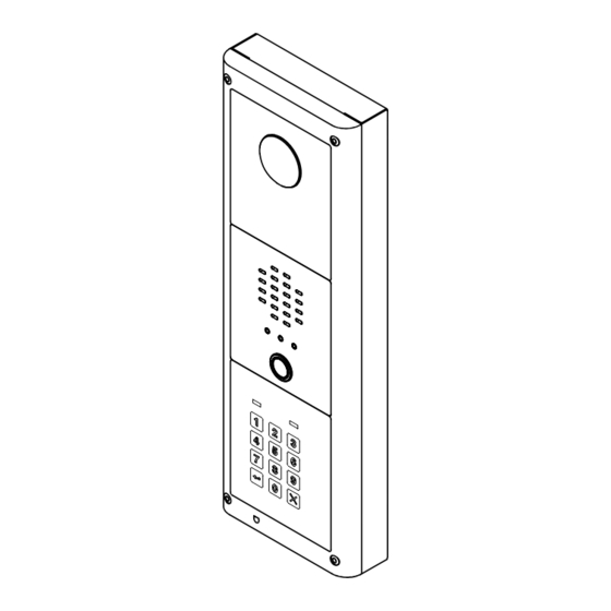
VRVK/6358 Series Vandal Resistant “6 wire Bus” videokit 4000 Series Surface and ush mounting door station installation INSTALLING A SURFACE MOUNT DOOR STATION 1. Place the surface box against the wall (165-170cm between the top of the box and the oor level as shown in Fig. 1) and mark the xing holes for the wall plugs and the hole for the cables ( g. - Page 17 VRVK/6358 Series Vandal Resistant “6 wire Bus” videokit Art. 6358 3.5" hands free colour display digital videophone 27 mm 102 mm DSW1 DSW2 Fig. 1 Fig. 2 DESCRIPTION LEGEND Surface mount hands free videophone incorporating a 3.5” Hi- Connection terminals Res full colour active matrix LCD monitor speci c for “6 wire”...
- Page 18 VRVK/6358 Series Vandal Resistant “6 wire Bus” videokit Art. 6358 3.5" hands free colour display digital videophone PUSH BUTTONS Answer push button On an incoming call, pressing this button allows the user to answer and converse with the visitor. The relevant LED will illuminate.
- Page 19 VRVK/6358 Series Vandal Resistant “6 wire Bus” videokit Art. 6358 3.5" hands free colour display digital videophone 2 WAY DIP SWITCH SW2 The two way dip-switch adjusts the impedance of the video signal. The default setting is “ON” for both switches (75 Ohm): when there are more videophones in parallel connection (without video distributor) both switches must be “ON”...
- Page 20 VRVK/6358 Series Vandal Resistant “6 wire Bus” videokit 6300 Series Wall mounting instructions Fig. 1 Fig. 2 Fig. 3 Fig. 4 Fig. 5 Fig. 6 Fig. 7 1. In order to install the videophone, it is necessary to remove the cover, which contains all the electronics, from the base: then rotate clockwise until you listen a “CLICK!”.
- Page 21 VRVK/6358 Series Vandal Resistant “6 wire Bus” videokit Art. 316 - Art. 316N 4 Way video distributor for system with balanced video signal DESCRIPTION ART. 316 4 Way video distributor for systems with balanced video signal. In white plastic ABS box 11x70x30mm surface mount. ART.
- Page 22 Art.140 Art.140 Title: Data creazione: Foglio 02/12/2015 Titolo: Data modifica: 02/12/2015 Videx Electronics S.p.A. Notes: Autore: Marco Rongoni Via del Lavoro 1, 63846 Monte Giberto )FM) Note: Cod.File: Phone: +39 0734 631669 - Fax +39 0734 631669 vrvk63h-001.dwg www.videx.it - info@videx.it - 22 - 66250694-EN - V5.1 - 30/09/20...
- Page 23 02/12/2015 02/12/2015 Marco Rongoni vrvk63h-002.dwg - 23 - 66250694-EN - V5.1 - 30/09/20...
- Page 24 - 24 - 66250694-EN - V5.1 - 30/09/20...
- Page 25 - 25 - 66250694-EN - V5.1 - 30/09/20...
- Page 26 02/12/2015 01/12/2015 Marco Rongoni vrvk63h-005.dwg - 26 - 66250694-EN - V5.1 - 30/09/20...
- Page 27 Art.140 Art.140 Title: Data creazione: Foglio 29/10/2015 Titolo: Data modifica: 29/10/2015 Videx Electronics S.p.A. Notes: Autore: Marco Rongoni Via del Lavoro 1, 63846 Monte Giberto )FM) Note: Cod.File: Phone: +39 0734 631669 - Fax +39 0734 631669 v vk-1-001-2e.d www.videx.it - info@videx.it - 27 - 66250694-EN - V5.1 - 30/09/20...
- Page 28 - 28 - 66250694-EN - V5.1 - 30/09/20...
- Page 29 - 29 - 66250694-EN - V5.1 - 30/09/20...
- Page 30 - 30 - 66250694-EN - V5.1 - 30/09/20...
- Page 31 DISPOSAL In accordance with the Legislative Decree no. 49 of 14 March 2014 “Implementation of the Directive 2012/19/EU on waste electrical and electronic equipment (WEEE)”. The crossed-out bin symbol on the equipment or on the packaging indicates that when the product reaches the end of its lifetime, it must be collected separately from mixed municipal waste.
- Page 32 MANUFACTURER VIDEX ELECTRONICS S.P.A. FABBRICANTE Via del Lavoro, 1 FABRICANT 63846 Monte Giberto (FM) Italy FABRICANTE Tel (+39) 0734 631669 FABRIKANT Fax (+39) 0734 632475 www.videx.it - info@videx.it CUSTOMER SUPPORT VIDEX ELECTRONICS S.P.A. UK Customers only: SUPPORTO CLIENTI www.videx.it - technical@videx.it...
Need help?
Do you have a question about the VRVK 6358 and is the answer not in the manual?
Questions and answers