Table of Contents

Related Manuals for Videx GSM4K/4G


Summary of Contents for Videx GSM4K/4G
- Page 1 4G GSM AUDIO INTERCOM KIT 4000 Series GSM Audio Intercom with Proximity GSM4K/4G GSM4KCR/4G Technical Manual We recommend 66250754-4G-EN This equipment is installed by a V2.0 - 28/03/22 Competent Electrician, Security or Communications Engineer.
- Page 2 This technical manual has been written and revised carefully. The guidance and the descriptions which are included in it are in reference to VIDEX parts and are correct at the time of print. However, subsequent VIDEX parts and technical manuals, can be subject to changes without prior notice.
-
Page 3: Table Of Contents
4000 Series GSM Audio Intercom with Proximity Contents Introduction.......................................4 System Components and Available Versions ..........................6 Art. 4810/4G Technical Information.............................. 14 Art. 4903 Technical Information..............................16 Art. 4850R Technical Information..............................20 Wiring Diagrams..................................... 22 Auxiliary Inputs/Outputs ................................24 USB & RS485 Connection to a PC..............................27 RS485 Network Connection................................ -
Page 4: Introduction
Alternatively a limited number of programming features can be carried out using the Videx SMS Wizard (for administrators) or for more in depth programming using the Videx SMS Wizard PRO (for installers), see notes on the GSM mobile Apps on page 67. - Page 5 SIM card and telephone number on the existing account. For more information regarding this contact the SIM card provider or visit their website, as this is a service NOT provided by VIDEX.
-
Page 6: System Components And Available Versions
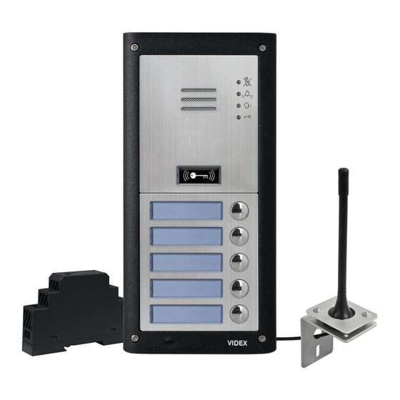
DESCRIPTION A system comprises of an intercom panel, power supply, SIM card (SIM card not provided by Videx) and antenna. The intercom panel is part of the Videx 4000 series modular design allowing it to be customised to the installation requirements for example including coded access, proximity access or including the correct number of call buttons (up to 50 call buttons). - Page 7 4000 Series GSM Audio Intercom with Proximity System Components and Available Versions CONNECTING ART. 4042 .. 4045 IDC BUTTON MODULES The 4G GSM module also includes an IDC connection that can be used to link the GSM module with the IDC button modules 4810-2/4G 4810-2/4G (Art.4042 ..
- Page 8 4000 Series GSM Audio Intercom with Proximity System Components and Available Versions GSM4K-8/4G & GSM4K-8S/4G GSM4K-9/4G & GSM4K-9S/4G GSM4K-10/4G & GSM4K-10S/4G Button Button Button offset = 00 offset = 00 offset = 00 Button config. Button config. Button config. jumper jumper jumper 6 - 10...
- Page 9 4000 Series GSM Audio Intercom with Proximity System Components and Available Versions BUTTON MATRIX WIRING Fig. 4 BUTTON MODULE WIRING NOTES If the 4G GSM module has 1 button (Art.4810-1/4G), the additional button module buttons should be wired starting from button number 2 (i.e.
- Page 10 The Art.434 GSM antenna, Fig.5, connects to the SMA female bulkhead connection on the rear of the 4G GSM module, see Fig.5 inset. A GSM antenna with an SMA male connector should be used. Also available to use with both the GSM4K/4G and GSM4KCR/4G series audiokits is the Art.434 block antenna, Fig.5 inset.
- Page 11 1A. The Art.HDR15-12, Fig.6, is a DIN rail mount slim line power supply that is supplied with both the GSM4K/4G and GSM4KCR/4G series audiokits. It has a mains voltage input of 230-240Vac, 50/60Hz and an adjustable 12Vdc output.
- Page 12 4000 Series GSM Audio Intercom with Proximity System Components and Available Versions GSM INTERCOM AUDIO KITS GSM4K-1/4G - flush mounting 1 Outdoor station composed of: 1 GSM antenna 1 Power supply 1 Art. 4810-1/4G: 1 button 4G GSM unit Art. 434 HDR-15-12 1 Art. 4851: Flush mounting box 12Vdc 1.25A...
- Page 13 4000 Series GSM Audio Intercom with Proximity System Components and Available Versions GSM4K 4G AUDIO KITS Additional GSM4K-n/4G (flush) kit versions are available from 3 way kits up to 12 way kits: GSM4K-3/4G up to GSM4K-12/4G. Each audio kit comes with the appropriate Art.4810/4G GSM module, appropriate extension IDC button module(s) and appropriate flush back box depending on the GSM4K-n/4G kit required (where n = the number of call buttons), refer to the audiokit table below.
-
Page 14: Art. 4810/4G Technical Information
4000 Series GSM Audio Intercom with Proximity Art. 4810/4G Technical Information ART. 4810/4G GSM MODULE 103mm 4810/4G GSM4K-4G - X.X.X Internal jumper JP2 Nameplate LED illumination adjustment Fig. 7 LEGEND Internal nameplate LED jumper (JP2) Micro USB connection Nameplate and proximity access reader Button matrix terminals Call button IDC male connector for expansion buttons... - Page 15 4 (busy, call, speak and open) Programming Method: SMS messaging, GSMSK PC software including the ‘over the air’ feature or GSM mobile apps - the Videx SMS Wizard (for administrators) or the Videx SMS Wizard PRO (for installers). RS485 Bus Connection: A, B and 0V...
-
Page 16: Art. 4903 Technical Information
4000 Series GSM Audio Intercom with Proximity Art. 4903 Technical Information ART. 4903 CODELOCK MODULE 103mm 4903 STEEL Note: Remove MOV MATTE jumper completely GUN METAL when using a relay to trigger a gate controller. RS485 BUS TERMINATION Fig. 8 DESCRIPTION LEGEND The module features 12 stainless steel buttons, backlit in blue (keys 0 - 9, ENTER... - Page 17 4000 Series GSM Audio Intercom with Proximity Art. 4903 Technical Information BACK LIGHT ADJUSTMENT JUMPER (JPL) The jumper JPL (Fig.8, ) is used to adjust Jumper Position Back light Operation the brightness and determine the operation Back light on low brightness in standby. Full of the backlit buttons.
- Page 18 4000 Series GSM Audio Intercom with Proximity Art. 4903 Technical Information PROGRAMMING AS A STANDALONE KEYPAD When using the Art.4903 as a standalone keypad refer to programming guide and flowchart below. All programming is carried out using the keypad. The programming menu is protected by an ENGINEER’S CODE, the factory default of which is six times 1 (“111111”).
- Page 19 4000 Series GSM Audio Intercom with Proximity Art. 4903 Technical Information PROGRAMMING WHEN INTEGRATED WITH THE GSM PRO (ART.4810) MODULE VIA THE RS485 BUS CONNECTIONS The Art.4903 can also be programmed using the GSMSK PC software (refer to the manual GSMSK_66251720-EN_V2-1 or later), by SMS text messaging (see notes on programming the GSM intercom on pages 37 - 66) and using the GSM mobile apps (see notes on the GSM mobile apps on page 67).
-
Page 20: Art. 4850R Technical Information
Store LED (green) and Delete LED (red) Videx SMS Wizard or Videx SMS Wizard PRO GSM mobile apps. It has a single onboard relay with common (C), normally open (NO) and normally closed (NC) connections and a switched 0V push to exit input (PTE) to enable the activation of the relay. - Page 21 4000 Series GSM Audio Intercom with Proximity Art. 4850R Technical Information The jumper should only be set to CLOSED on long cable distances and on the end of line of the RS485 bus, in which case the RS485 bus should have end of line termination at both ends. PROGRAMMING THE RELAY TIME (00, 01 - 99) In standby the green store LED and red delete LED on the back of the module will be ON, the yellow tens and units LED’s will be OFF.
-
Page 22: Wiring Diagrams
4000 Series GSM Audio Intercom with Proximity Wiring Diagrams GSM4K/4G CONNECTIONS Fig.20 shows the wiring connections for a GSM4K-1/4G and a GSM4K-1S/4G audio kit. Art.4810/4G For fail secure locks a MOV must also be fitted across terminals C & NO and for fail safe locks across C &... - Page 23 CONNECTING TO A GATE CONTROLLER For a GSM4K/4G series audio kit if the 4G GSM module is going to be connected to an electric gate then the wires from the gate controls can be connected directly into the C and NO relay terminals on the GSM module, as shown in Fig.23.
-
Page 24: Auxiliary Inputs/Outputs
4000 Series GSM Audio Intercom with Proximity Auxiliary Inputs/Outputs AUXILIARY OUTPUT AO1 The auxiliary output AO1 has six modes 00 - 05 and can be set using the A1M command (refer to pages 43 - 44 for the list of A1M programming modes). - Page 25 4000 Series GSM Audio Intercom with Proximity Auxiliary Inputs/Outputs AO1 = MODE 03, ‘DIVERT CALLS TO MASTER NUMBER’ Normally Open It is possible to have the GSM call buttons diverted to the master Art.4810/4G (NO) switched number (outside certain hours) using the TBA timeband feature input to ENABLE (refer to timeband TBA programming notes on page 47).
- Page 26 4000 Series GSM Audio Intercom with Proximity Auxiliary Inputs/Outputs AUXILIARY OUTPUT AO2 The auxiliary output AO2 is an open collector output (switched low, 150mA max.) and can be used to switch a negative trigger onto a transistor switched device, for example an Art.506N, for the programmed A2T time (refer to notes on page 44 setting the A2T time).
-
Page 27: Usb & Rs485 Connection To A Pc
4000 Series GSM Audio Intercom with Proximity USB & RS485 Connection to a PC CONNECTIONS TO A PC The 4G GSM module includes three options for connecting to a PC: via a USB connection or via an RS485 connection. All methods of connection are to allow for ease of programming and monitoring using the GSMSK PC software. -
Page 28: Rs485 Network Connection
4000 Series GSM Audio Intercom with Proximity RS485 Network Connection ART. 4903 NETWORK CONNECTION USING RS485 As mentioned previously (refer to Fig.13, page 19) the Art.4903 keypad can be connected via the RS485 bus terminals on the 4G GSM module allowing additional features of the GSM module to become available, which include: •... - Page 29 4000 Series GSM Audio Intercom with Proximity RS485 Network Connection SECURED BY DESIGN INTERNAL Art.2813 UNIT ID.1 CONFIGURATION SECURED AREA Relay time set to 1 second on 1st power up Aux A1 time set to 5 secs. on 2nd power up EXTERNAL UNSECURED AREA Aux A2 time set to 0, latch mode on 3rd power up...
-
Page 30: General Directions For Installation
Videx DO NOT recommend these types of cable. GENERAL INSTALLATION NOTES •... - Page 31 The system MUST be installed in accordance with the current I.E.T. regulations (in particular I.E.T. Wiring Regulations, Eighteenth Edition BS7671:2018 for the UK), or the appropriate standards of your country if installing overseas, in particular Videx recommends: • Connecting the system to the mains through an all-pole circuit breaker (refer to Fig.43) which shall have contact...
- Page 32 IMPORTANT NOTE: IT IS IMPORTANT TO REGULARLY MAINTAIN THE “UP KEEP” OF THE GSM PANEL (CLEANING AND GENERAL MAINTENANCE ETC.) ANY FAULT OR DAMAGE THAT MAY OCCUR TO THE GSM PANEL DUE TO THE LACK OF CLEANING AND MAINTENANCE IS NOT THE RESPONSIBILITY OF VIDEX. 4000 Series GSM Audio Intercom - Technical Manual - 32 - 66250754-4G-EN - V2.0 - 28/03/22...
-
Page 33: Fitting The Sim & Connecting Power
4000 Series GSM Audio Intercom with Proximity Fitting the SIM & Connecting Power FITTING THE SIM CARD AND CONNECTING THE POWER TO THE GSM INTERCOM After installing the power supply, antenna, lock output and any auxiliary devices as shown in this manual and before powering up, a SIM card must be installed (the SIM must already be registered with the network provider). -
Page 34: Reset Procedure
4000 Series GSM Audio Intercom with Proximity Reset Procedure RESETTING THE GSM MODULE TO FACTORY DEFAULTS There are two ‘hard-wired’ reset options available. The first will reset the master code only and the second will reset everything and clear all the stored telephone numbers, proximity cards, access codes, timebands and all settings. RESETTING THE MASTER CODE TO 1111 (4x1) 1. -
Page 35: 4000 Series Back Box Installation
4000 Series GSM Audio Intercom with Proximity 4000 Series Back Box Installation EXAMPLE: INSTALLING A 4000 SERIES FOUR MODULE BACK BOX Fig. 62 Fig. 63 Fig. 64 Fig. 65 Fig. 66 Fig. 67 Fig. 68 Fig. 69 Fig. 70 Fig. 71 Fig. - Page 36 4000 Series GSM Audio Intercom with Proximity 4000 Series Back Box Installation INSTALLING A SURFACE MOUNT DOOR STATION 1. Place the surface box against the wall (165-170cm between the top of the box and the floor level as shown in Fig.62), mark the fixing holes for the wall plugs and the hole for the cables...
-
Page 37: Programming The Gsm Intercom
GSMSK PC software (ver 4.1.0.35 or later), also refer to the programming manual GSMSK_66251720-EN_V2-1 (or later) or by using the GSM mobile apps: Videx SMS Wizard (for administrators) and the Videx SMS Wizard PRO (for installers and engineers) also see additional notes on page 67. - Page 38 4000 Series GSM Audio Intercom with Proximity Programming the GSM Intercom Store balance check dial string 1111SDL”*#1345#” Check credit balance 1111BAL? 45 - 46 Store master telephone no. 1111STM”07771234567” Latch the relay 1111RLA Unlatch the relay 1111RUL Latch the auxiliary AO1 output 1111A1L Unlatch the auxiliary AO1 output A1U 1111A1U...
- Page 39 4000 Series GSM Audio Intercom with Proximity Programming the GSM Intercom Store an access code with an 1111PINnnn”code”An nnn = 000 - 399 or An default = all 54 - 55 access level (including storing in nnn - optional access unless known and next free location &...
- Page 40 MEM (DIVERT 2) 001 = 0771234567 VIDEX 4G STORING THE PRIMARY AND DIVERT NUMBERS IN A SINGLE TEXT MESSAGE (USING STN) It is also possible to program a primary telephone number and three divert numbers for a particular call button in a single text message instead of using the individual programming codes STD (1st divert), STE (2nd divert) and STF (3rd divert).
- Page 41 MEM (DIVERT 1) 005 = 01912241558 MEM (DIVERT 2) 005 = 07771234567 MEM (DIVERT 3) 005 = 01912241559 VIDEX 4G Remember to include “ and , where appropriate. STORING A DIAL TO OPEN NUMBER (STR) Dial in door release allows users to release the door/gate simply by dialling the telephone number of the SIM in the GSM intercom panel.
- Page 42 MEM OPEN 006 = 01912241559 MEM OPEN 007 = 07897123456 VIDEX 4G Remember to include “ and , where appropriate. In the example above if locations 001 and 002 already had numbers programmed then the dial to open numbers (DTO) n1, n2, n3, n4 and n5 would be stored in the GSM starting from location 003 up to 007.
- Page 43 Note that when using this command the full telephone number will be required otherwise the GSM will respond with: NOT FOUND VIDEX 4G STORE A TEMPORARY DIAL TO OPEN NUMBER (TDR) Using the following programming command 1111TDR”tele”T? it is also possible to store a temporary dial to open number (DTO) in the GSM module.
- Page 44 4000 Series GSM Audio Intercom with Proximity Programming the GSM Intercom is open or closed. See example, Fig.28, on page 24. Divert Calls to Master Number: nn = 03 When in this mode, the AO1 terminal is used exclusively for monitoring the status of a switched input to decide if calls should be diverted to the master number or not.
- Page 45 IMPORTANT NOTE: Videx are only aware of the balance check dial string codes for the network providers mentioned above. Check dial string codes for other networks are currently unavailable at this time. Please also note that this programming function is only applicable for pay as you go SIM cards.
- Page 46 4000 Series GSM Audio Intercom with Proximity Programming the GSM Intercom 1111BAL? Check current balance of the SIM in the GSM unit, send a confirmation text back to the sender. In addition to this feature the GSM intercom also has the facility to monitor the available credit and then text the user to inform them when the credit has fallen below £5.00, €5.00 or $5.00.
- Page 47 The GSM intercom will reply with the following text: TB = 08001700,Su,Mo,Tu,We,Th,Fr,Sa VIDEX 4G Example 2: To set a timeband where calls are to be received on Mondays, Tuesdays and Fridays only, from 10:00am until 3:30pm, the following text can be sent to the GSM intercom: 1111TBA”10001530”,Mo,Tu,Fr?
- Page 48 The GSM intercom will reply with the following text: ATB0 = 08001400,Su,Sa VIDEX 4G Example 2: To set timeband 1 to allow for proximity fobs/cards, access codes and dial to open numbers to be active between 2:00pm in the afternoon until 3:00pm in the afternoon and for Mondays, Wednesdays and Fridays only, the following text can be sent to the GSM intercom, remembering to use 24hr clock notation: 1111ATB1”14001500”,Mo,We,Fr?
- Page 49 Including a ? at the end of the command the GSM intercom will reply with the following text: AL8 = “1010101010”,”11001100” VIDEX 4G Remember that each timeband would be programmed using the store timeband command ATB, see previous page. USING ACCESS LEVELS WITH DIAL TO OPEN NUMBERS (STR) It is also possible to assign access levels to dial to open numbers using the STR programming command (also refer to STR programming described on pages 41 and 42).
- Page 50 MEM OPEN 005 = 01912241558,A2 MEM OPEN 006 = 07771234567,A1 VIDEX 4G In the example the DTO numbers are stored from memory location 004 onwards as this is the next available location and the access level for each DTO number is shown after the telephone number being stored.
- Page 51 4000 Series GSM Audio Intercom with Proximity Programming the GSM Intercom • The DTP command sets the DTMF tone required (from 0 - 9) after a call is answered for button 1. • The DTD command sets the DTMF tone required (from 0 - 9) after divert 1 call is answered for button 1. •...
- Page 52 • 955/T or 955/C = Videx fobs or cards. These fobs and cards have no site code and have a 5 digit user code, so the PBY function must be set to 02 (the default setting, checking for 2 bytes).
- Page 53 GSM intercom will reply with the following text: FOB 004 = 0000021092,A5 VIDEX 4G Example 2: Programming a PBX1E or PBX2 with a 3 digit site code of 241, a 5 digit user code of 15432, storing it to the next free...
- Page 54 The GSM intercom will reply with the following text: DELETED VIDEX 4G STORE AN ACCESS CODE TO A KNOWN LOCATION (000 - 399) OR STORE IN THE NEXT AVAILABLE LOCATION (PIN) If an Art.4903 keypad(s) has been connected to the GSM using the RS485 connection this feature allows up to 400 (000 - 399) additional access codes to be programmed into the GSM intercom.
- Page 55 Including a ? at the end of the programming command the GSM intercom will reply with the following text: PIN 008 = 654321,1,A4 VIDEX 4G In this example the 6 digit access code will be stored in memory location 008 and will automatically be setup to trigger relay 1 and the code assigned to access level 4.
- Page 56 The GSM intercom will reply with the following text: TMP PIN TMP=234567,12 VIDEX 4G In this example the reply from the GSM will simply confirm that the temporary code has been stored and which relays the code will activate.
- Page 57 The GSM intercom will reply with the following text: DELETED VIDEX 4G In the FDC example on the previous page the full 4 - 8 digit code length is required for the DEC programming command. DELETE ALL TEMPORARY ACCESS CODES (DEP) This feature allows the user to delete all temporary access codes from the GSM intercom.
- Page 58 The GSM intercom will reply with the following text: STORED IN nnn VIDEX 4G where nnn = the dial to open location of where the number is stored. Example 2: Find dial to open location of the telephone number using the last 4 digits of the number 4567, the following text can be sent to the GSM intercom: 1111FDT”4567”?
- Page 59 For the application of these commands please contact Videx Technical on tel: 0191 224 3174 for UK based customers and Videx customer support on tel: +39 0734 631699 for overseas customers.
- Page 60 Therefore to obtain the GSM’s IMEI number, located on the main hardware chip internally, the GSM module will have to be opened. The IMEI number is printed on the main chip label, see Fig.82. It is recommended that you contact Videx Technical on tel: 0191 224 3174 for UK based customers and Fig. 82 Videx Customer Support: +39 0734 631669 for overseas customers for advise on how to do this.
- Page 61 SIM cards and their pay as/and you go SIM cards. The table below provides the APN details for the most common network providers in the UK that have been gathered by VIDEX and are correct at time of print. Please note that these details may also be subject to change without prior notice by the respective network provider, therefore VIDEX are not responsible for any errors, omissions or discrepancies that may effect the APN setup.
- Page 62 4000 Series GSM Audio Intercom with Proximity Programming the GSM Intercom online or via either of the two GSM mobile apps - the Videx SMS Wizard (for administrators) and the Videx SMS Wizard PRO (for installers/engineers). The following command is used to store the username and password for each of the GSM modules on the GSM module list.
- Page 63 The ? is included in the example for a confirmation back from the GSM. The GSM intercom will reply with the following text: TZ+04 VIDEX 4G UTC TIME ZONE FOR COUNTRIES BEHIND UTC (TZ-) If the GSM module is being installed in a Time Zone behind Time Zone (UTC+0) then the command 1111TZ-nn can be used to set the correct time behind.
- Page 64 The ? is included in the example for a confirmation back from the GSM. The GSM intercom will reply with the following text: TZ-20 VIDEX 4G DAYLIGHT SAVINGS TIME ADJUSTMENT (DST) If the GSM module is being installed in a time zone that allows for daylight savings time then the automatic DST adjustment feature can be enabled or disabled.
- Page 65 GSM intercom: 1111BOF85? Including a ? at the end of the command the GSM intercom will reply with the following text: BOF = 85 VIDEX 4G Button offset = 00 Button offset = 85 Button config. jumper R position for Button config.
- Page 66 Including a ? at the end of the command the GSM intercom will reply with the following text: BOF = 81 VIDEX 4G With the offset value now set to 81 (and therefore enabled) the Art.4810-1/4G onboard button would become button 6 and the Art.4045 buttons, with the config.
-
Page 67: The Gsm Mobile Apps
4000 Series GSM Audio Intercom with Proximity The GSM Mobile Apps VIDEX SMS ACCESS, SMS WIZARD & SMS WIZARD PRO In addition to programming by direct text messages or using the GSMSK PC programming software it is also possible to program the GSM intercom using the GSM... -
Page 68: System Operation
4000 Series GSM Audio Intercom with Proximity System Operation MAKING A CALL AND CANCELLING A CALL FROM THE GSM INTERCOM TO THE PHONE 1. To place a call press the desired call button. Two beeps will be heard from the GSM module to indicate the call has been placed. 2. - Page 69 4000 Series GSM Audio Intercom with Proximity System Operation RELEASING THE DOOR/GATE USING THE ONBOARD PROXIMITY READER For the onboard reader to operate correctly it must first be enabled, the correct number of bytes setup and fobs/cards stored using the EPR, PBY and FOB commands (refer to the relevant programming notes on previous pages). In standby the status LED’s on the front of the GSM will be switched OFF.
- Page 70 4000 Series GSM Audio Intercom with Proximity System Operation OPERATION WHEN CONNECTED TO THE GSM INTERCOM VIA RS485 When the Art.4903 codelock is connected to the GSM intercom via the RS485 terminals it can operate with additional access control features (refer to the notes and Fig.13 on page 19, to the notes and Fig.38 on page 29, and also the programming features in the programming section of this manual).
-
Page 71: User Commands
4000 Series GSM Audio Intercom with Proximity User Commands USER COMMAND TABLES The following user command table shows the user commands that can be carried out during a call. Successful commands are signalled by two beeps from the telephone, errors are signalled by four beeps. IMPORTANT NOTE: When the ED# function has been enabled the user must press the # button on their phone before pressing any of the following user commands (also refer to page 51 for further information). -
Page 72: Additional User Information
Art.434/BLOCK antenna is repositioned, where permissible, at the highest point to achieve the best signal. Where this is not possible an alternative high gain antenna can be used, in particular Videx recommends using the Art.434/HG/5M or Art.434/ HG/15M high gain antennas or another suitable 4G GSM antenna with a standard SMA male connector. - Page 73 4000 Series GSM Audio Intercom with Proximity Additional User Information Single short beep while A valid text message has been received and None, this is normal. the system is in standby processed. and not being used. Double beep, a single Button pressed but no number stored.
- Page 74 4000 Series GSM Audio Intercom with Proximity Additional User Information Single short beep Fob/card presented to the expansion reader is The fob/card requires programming into the GSM followed by a short not programmed. module. double beep. No beeps. The onboard The onboard reader has not been enabled Enable the onboard proximity reader.
-
Page 75: User Management
MANAGING GSM EVENTS REMOTELY Users can also remotely monitor events in real-time from the GSM module using Videx’s web browser based events application. These events can then be viewed on any device such as a tablet, smartphone, laptop and PC. -
Page 76: Troubleshooting
UNICODE and is set to either GSM alphabet or Automatic. This can ususally be done via the etc. settings icon on the smartphone. If you are unsure of how to do this Videx recommend consulting with the user’s manual that came with the smartphone or consulting directly with the manufacturer of the smartphone. - Page 77 3. After the GSM intercom has rebooted test the door opening feature from the telephone during a call. If neither of the above solutions resolve the problem then please contact Videx technical on tel: 0191 224 3174 for further assistance. For overseas customers contact Videx customer support on tel: (+39) 0734 631 699 for further assistance.
-
Page 78: General Information
Additional port forwarding, server setup and configuration information can be found in Videx application note: • AN0046_RemotelyProgramming4GIntercomsViaPCSoftware. Additional programming setup and guidance on the Videx SMS Wizard PRO and Videx SMS Wizard app can be found in the following Videx application notes:... - Page 79 4000 Series GSM Audio Intercom with Proximity DISPOSAL In accordance with the Legislative Decree no. 49 of 14 March 2014 “Implementation of the Directive 2012/19/EU on waste electrical and electronic equipment (WEEE)”. The crossed-out bin symbol on the equipment or on the packaging indicates that when the product reaches the end of its lifetime, it must be collected separately from mixed municipal waste.
- Page 80 MANUFACTURER VIDEX ELECTRONICS S.P.A. FABBRICANTE Via del Lavoro, 1 FABRICANT 63846 Monte Giberto (FM) Italy FABRICANTE Tel (+39) 0734 631669 FABRIKANT Fax (+39) 0734 632475 www.videx.it - info@videx.it FABRICANTE الرس كة المص ن ِّ عة CUSTOMER SUPPORT VIDEX ELECTRONICS S.P.A.
Need help?
Do you have a question about the GSM4K/4G and is the answer not in the manual?
Questions and answers