
Related Manuals for Videx GSM4K


Summary of Contents for Videx GSM4K
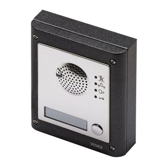
- Page 1 English GSM AUDIO INTERCOM KIT 4000 Series GSM Audio Intercom with Proximity GSM4K GSM4KC Technical Manual We recommend ENUK This equipment is installed by a V1.4 Competent Electrician, Security or 25/01/17 Communications Engineer.
-
Page 2: Declaration Of Conformity
CE conformity marking indicates that the product respects the requirements of the All Countries: UK Customers: applicable European Community Directives in force specifically EMC 2004/108/ VIDEX ELECTRONICS S.P.A. VIDEX SECURITY LTD. ECC, LVD 2006/95/ECC and CE-MARKING 93/68/ECC. CE marking is applied by the www.videx.it www.videxuk.com... -
Page 3: Table Of Contents
4000 Series GSM Audio Intercom with Proximity Contents Introduction .......................................4 System Components and Available Versions ..........................7 Technical Information ..................................13 Wiring Diagrams ..................................... 19 Auxiliary Inputs/Outputs ................................21 General Directions for Installation ..............................25 Reset Procedure ....................................29 4000 Series Back Box Installation ..............................30 Programming the GSM Intercom .............................. -
Page 4: Introduction
SIM CARD SELECTION A SIM card is required for this product but not supplied by Videx. The digital GSM intercom can only accept a standard size SIM card (refer to the following SIM card size chart), both a micro-SIM and nano-SIM are not suitable. It is recommended to choose the SIM card which has the best coverage for the area in which the intercom panel will be installed. - Page 5 GSM PRO module. To gain access to the GSM module and obtain this number the module will have to be opened. It is recommended that you contact Videx Technical on tel: 0191 224 3174 for advise on how to do this.
- Page 6 All providers offer this service. You will need to either ring them or e-mail them to set this up. Automatic top ups should also have a monthly limit. We would suggest a limit of £50.00 which should be more than enough. This service is not provided by Videx. 4000 Series GSM Audio Intercom - Technical Manual...
-
Page 7: System Components And Available Versions
DESCRIPTION A system comprises of an intercom panel, power supply, SIM card (SIM card not provided by Videx) and antenna. The intercom panel is part of the Videx 4000 series modular design allowing it to be customised to the installation requirements for example including coded access or including the correct number of call buttons (up to 50 call buttons). - Page 8 Both surface and flush back boxes and mounting frames are available. The size of the frame will depend on the number of modules that make up the GSM4K/GSM4KC kit. The last digit of the frame code indicates the number of modules it will take. Frames are available in gun metal gray finish, chrome finish (suffix \C to the frame code) or gold finish (suffix \G to the frame code).
-
Page 9: Surface Back Boxes And Mounting Frames
4000 Series GSM Audio Intercom with Proximity System Components and Available Versions Flush Back Boxes and Mounting Frames Art. 4851 Art. 4852 Art. 4853 Fig. 6 Flush Back Box Dimensions Part No. Housed Modules Front Frame (W x H x D) mm Back Box (W x H x D) mm Art.4851 135 x 160 x 15.7... - Page 10 The Art. 4810 GSM PRO intercom is designed to work with power supplies in the range of 12Vdc or 24Vac/dc and should be capable of supplying a constant current of no less than 2A. Both the GSM4K and GSM4KC kits are supplied with the Art. 324 power supply (refer to Fig.8).
- Page 11 4000 Series GSM Audio Intercom with Proximity System Components and Available Versions GSM INTERCOM AUDIO KITS GSM4K-1 - flush mounting 1 Outdoor station composed of: 1 GSM antenna 1 Power supply 1 Art. 4810-1: 1 button GSM (pro) unit Art. 432 Art. 324 1 Art. 4851:...
- Page 12 GSM4K AUDIO KITS Additional GSM4K-n (flush) kit versions available from 3 way kits up to 12 way kits: GSM4K-3 up to GSM4K-12. Each audio kit comes with the appropriate Art.4810 GSM module, appropriate extension button module(s) and appropriate flush back box depending on the GSM4K-n kit required (where n = the number of call buttons).
-
Page 13: Technical Information
4000 Series GSM Audio Intercom with Proximity Technical Information ART.4810 GSM (PRO) MODULE Antenna connection 103mm SIM card holder Speaker volume dip-switches R02A Internal jumper JP2 Nameplate LED illumination adjustment Micro USB connection Micro USB connection call progress LED’s (busy, call, speak, open) call progress LED’s (busy, call, speak, open) nameplate and nameplate and... - Page 14 4000 Series GSM Audio Intercom with Proximity Technical Information TERMINAL CONNECTIONS AND JUMPER JP2 Terminal Description +12V 12 - 24Vdc or ac power. 0V ground power. Auxiliary output 1 (open collector, 150mA max.). Auxiliary output 2 (open collector, 150mA max.). Common relay contact.
- Page 15 4000 Series GSM Audio Intercom with Proximity Technical Information TECHNICAL SPECIFICATION Working Voltage : 12 - 24Vdc or ac +/- 10% Standby Current : approx. 60mA Max. Current : approx. 500mA (max.) Call Buttons : up to 50 (max.) Telephone Numbers per Button : 4 telephone numbers (1 primary, 3 diverts) Dial to Open Numbers : up to 1000 (max.)
- Page 16 4000 Series GSM Audio Intercom with Proximity Technical Information TERMINAL CONNECTIONS Connection Description 12-24V AC or DC power input 0V power input Relay 1 common connection Relay 1 normally open connection Relay 1 normally closed connection Relay 2 common connection Relay contacts: Relay 2 normally open connection 3A@24Vac/dc...
- Page 17 4000 Series GSM Audio Intercom with Proximity Technical Information ART. 4800M PROGRAMMING GUIDE Initial Programming All programming is carried out using the keypad. The programming menu is protected by an engineer’s code. The factory default engineer’s code is ‘111111’ (6x1). This code can be changed to any 4 to 8 digit engineer’s code during the programming, but must be different to the access codes used to gain entry.
- Page 18 4000 Series GSM Audio Intercom with Proximity Technical Information Re-programming the Codelock If the Art.4800M codelock has been programmed with an existing access code and it needs to be changed then follow the flow chart below to re-program a new acces code: Enter the existing engineer’s code.
-
Page 19: Wiring Diagrams
4000 Series GSM Audio Intercom with Proximity Wiring Diagrams GSM4K CONNECTIONS Fig.15 shows the wiring connections for a GSM4K-1 / GSM4K-1S audio kit. for fail safe lock wiring move lock wire from NO to NC Fig. 15 GSM4KC CONNECTIONS Fig.16 shows connections for a GSM4KC-1 / GSM4KC-1S audio kit. - Page 20 4000 Series GSM Audio Intercom with Proximity Wiring Diagrams CONNECTING TO A GATE CONTROLLER (USING THE ART.120 OPTO-ISOLATOR PCB) If the GSM intercom is going to be connected to a set of gate controls then it is recommended that the GSM relay is connected with the Art.120 opto-isolator pcb provided with the GSM kit.
-
Page 21: Auxiliary Inputs/Outputs
4000 Series GSM Audio Intercom with Proximity Auxiliary Inputs/Outputs AUXILIARY OUTPUT AO1 The auxiliary output AO1 has six modes 00 - 05 and is set using the A1M command (refer to page 35 for full list of A1M programming modes). It is an open collector output (switched low, 150mA max.) and depending on the mode it is set to will determine how the AO1 output behaves. - Page 22 4000 Series GSM Audio Intercom with Proximity Auxiliary Inputs/Outputs AO1 SET TO MODE 02, ‘STATUS INDICATION’ When set to mode 02 auxiliary output AO1 is used exclusively as a monitoring input. For example, checking if a gate/door is open or closed. Once set the AO1 input status can be interrorgated in two ways: 1.
- Page 23 4000 Series GSM Audio Intercom with Proximity Auxiliary Inputs/Outputs AO1 SET TO MODE 04, ‘CALL ACTIVATED (TIMED)’ Similar to mode 00, however, when set to mode 04 auxiliary output AO1 will activate when the call begins and deactivate when the auxiliary AO1 time expires, see Fig.23.
- Page 24 4000 Series GSM Audio Intercom with Proximity Auxiliary Inputs/Outputs AUXILIARY OUTPUT AO2 The auxiliary output AO2 is an open collector output (switched low, 150mA max.) and can be used to switch a negative trigger onto a transistor switched device, for example an Art.506N, for the programmed A2T time (refer to notes on page 35 setting the A2T time).
-
Page 25: General Directions For Installation
Videx DO NOT recommend these types of cable. GENERAL INSTALLATION NOTES •... - Page 26 CONNECTION TO MAINS, SAFETY AND GUIDANCE NOTES IMPORTANT: PLEASE READ THESE INSTRUCTIONS CAREFULLY BEFORE COMMENCING WITH THE INSTALLATION. Videx recommends that any cabling and Videx product be installed by a competent and qualified electrician, security installation speclialist or communications engineer.
- Page 27 4000 Series GSM Audio Intercom with Proximity General Directions for Installation Fig. 30 Fig. 31 Fig. 32 PANEL CARE The door panel’s facia is either mirror finish stainless steel or matt finish aluminium. It is important that the facia is cleaned on regular occasions to prevent dirt build up and tarnishing of the metal.
- Page 28 4000 Series GSM Audio Intercom with Proximity General Directions for Installation 2. The SIM holder is hinged and will open out to the left, see Fig.34. Fig. 34 3. Place the SIM card into the holder (it will only fit one way, see Fig.35) and fold the holder back down, see Fig.36. Fig.
-
Page 29: Reset Procedure
4000 Series GSM Audio Intercom with Proximity Reset Procedure RESETTING THE GSM MODULE TO FACTORY DEFAULTS There are two reset modes available. The first will reset the master code only and the second will reset everything and clear all stored telephone numbers, proximity cards and settings. RESETTING THE MASTER CODE TO 1111 (4x1) 1. -
Page 30: 4000 Series Back Box Installation
4000 Series GSM Audio Intercom with Proximity 4000 Series Back Box Installation EXAMPLE: INSTALLING A 4000 SERIES FOUR MODULE BACK BOX Fig. 38 Fig. 39 Fig. 40 Fig. 41 Fig. 42 Fig. 43 Fig. 44 Fig. 45 Fig. 46 Fig. 47 Fig. - Page 31 4000 Series GSM Audio Intercom with Proximity 4000 Series Back Box Installation INSTALLING A SURFACE MOUNT DOOR STATION 1. Place the surface box against the wall (165-170cm between the top of the box and the floor level as shown in Fig.38) and mark the fixing holes for the wall plugs and the hole for the cables E (Fig.39).
-
Page 32: Programming The Gsm Intercom
4000 Series GSM Audio Intercom with Proximity Programming the GSM Intercom PROGRAMMING THE GSM INTERCOM Programming the GSM PRO intercom can be carried out in two ways, either by sending text (SMS) messages or by using the GSMSK PC software (ver 3.0.0.2 or later). IMPORTANT NOTE: When you are required to use “... - Page 33 4000 Series GSM Audio Intercom with Proximity Programming the GSM Intercom Store time band 1111TBA”06002300” HHMMHHMM 00002359 Check/Set date & time 1111CLK”yy/mm/dd,hh:mm”? yy/mm/dd,hh:mm n/a Input status check and set 1111CHK? 39 - 40 Silent dialling mode 1111AUEnn nn = 00 or 01 Send tone after answer (But 1) 1111DTPn n = 0 - 9 or X...
- Page 34 4000 Series GSM Audio Intercom with Proximity Programming the GSM Intercom nnn is a button number between 001 & 050. The telephone number y can be a maximum of 30 digits. For example: to store the number 01912243174 for button 5 and three divert numbers (if that one is not answered or busy) of 01912241558, 07771234567 and 01912241559 respectively, the following SMS messages would be sent to the GSM intercom: 1111STN005”01912243174”...
- Page 35 4000 Series GSM Audio Intercom with Proximity Programming the GSM Intercom SET AUXILIARY OUTPUT AO1 TIME (A1T, FOR A1M = 01 ONLY) The auxiliary output AO1 time can be set from 01 - 99 seconds or latching (set the AO1 output time to 00 for latched mode. In latch mode the AO1 output will stay triggered until the relevant command is sent again to unlatch the AO1 output.
- Page 36 4000 Series GSM Audio Intercom with Proximity Programming the GSM Intercom 1111NODnn Store the time nn = time in days (e.g. nn = 07, time = 7 days). 1111NODnn? Store the time nn = time in days. Also send a confirmation text back to the sender. 1111NOD? Query the current stored time.
- Page 37 IMPORTANT NOTE: Videx are only aware of the balance check dial string codes for the network providers mentioned above. Check dial string codes for other networks are currently unavailable at this time. Please also note that this programming function is only applicable for pay as you go SIM cards.
- Page 38 4000 Series GSM Audio Intercom with Proximity Programming the GSM Intercom The correct balance check string must be stored using the SDL code (see store balance check dial string). A mobile phone number that is to receive the ‘balance low’ text must be stored in the master telephone number location using the STM code (refer to ‘store master telephone number’...
- Page 39 The GSM PRO intercom will reply with the following text: CLK = 16/04/18, 10.05 VIDEX GSM CHECK INPUT STATUS (CHK) IMPORTANT NOTE: This feature is only applicable when auxiliary output AO1 mode has been set to mode 02. If auxiliary output AO1 is set to any other mode then this feature will not work (also refer to example on page 22 and setting auxiliary output AO1 mode, A1M, on page 35).
- Page 40 Check the current status of auxiliary output AO1, the following text can be sent to the GSM PRO intercom: 1111CHK? The GSM PRO intercom will reply with either of the following texts: IN = OP IN = CL VIDEX GSM VIDEX GSM (status open) (status closed) SILENT DIALLING MODE (AUE) When the GSM PRO intercom is calling the telephone number stored there is a choice of either hearing the ringing noise from the intercom panel or just hearing beeps to indicate a call is in progress.
- Page 41 4000 Series GSM Audio Intercom with Proximity Programming the GSM Intercom ENABLE THE DIAL ‘0’ ON ANSWER FUNCTION (EDZ) When enabled this feature allows an incoming call to be diverted to the programmed divert telephone number if the ‘0’ button on the telephone has not been pressed after answering the call.
- Page 42 • 955/T or 955/C = Videx fobs or cards. These fobs and cards have no site code and have a 5 digit user code, so the PBY function must be set to 02 (the default setting, checking for 2 bytes).
- Page 43 The GSM PRO intercom will reply with the following text: STORED IN nnn VIDEX GSM (where nnn = the dial to open location of where the number is stored). Example 2: Find dial to open location of the telephone number using the last 4 digits of the number 4567, the following text can be sent to the GSM PRO intercom: 1111FDT”4567”?
- Page 44 The following commands are reserved for the technical department for interrorgating the GSM PRO module when testing and applying specific additional features that are not covered in this technical manual. For the application of these commands please contact Videx Technical on tel: 0191 224 3174. PROGRAM BY ‘AT’ COMMANDS (PRG) This is an advanced feature of the system which can allow an ‘AT’...
-
Page 45: System Operation
4000 Series GSM Audio Intercom with Proximity System Operation MAKING A CALL FROM THE GSM INTERCOM Press the required call button. Two beeps will be heard to indicate the call has been placed (see Fig.56). The busy LED will illuminate and the call LED will flash to indicate that the system is engaged and a call is in progress (see Fig.57). -
Page 46: User Commands
4000 Series GSM Audio Intercom with Proximity User Commands USER COMMAND TABLES The following user command table shows the user commands that can be carried out during a call. Successful commands are signalled by two beeps from the telephone, errors are signalled by four beeps. FUNCTION 1st KEY TO PRESS 2nd KEY TO PRESS... -
Page 47: Additional User Information
BER the better. The example below shows the reply to expect from the GSM PRO: SIGNAL = 31 BER = 0 OK VIDEX GSM DIALLING INTO THE GSM INTERCOM FROM ANOTHER TELEPHONE There are three possible outcomes to dialling into the GSM PRO intercom depending on the telephone number you are dialling in from and the features setup during programming. - Page 48 4000 Series GSM Audio Intercom with Proximity Additional User Information Four long beeps. Not registered with a network provider but still Leave it a short while to see if it manages to find trying. the network. If the beeps repeat every 30 seconds then try moving the antenna to a better location or changing the SIM to another network provider.
-
Page 49: User Management
4000 Series GSM Audio Intercom with Proximity User Management RECORD SHEET In order to manage the GSM PRO intercom effectively it is recommended that an up to date record sheet is kept for all the programming particularly if there is a high volume of telephone numbers and fob/cards stored in the GSM intercom. This will also be useful if any future changes need to be made. -
Page 50: Troubleshooting
4000 Series GSM Audio Intercom with Proximity Troubleshooting SYSTEM CHECKS AND TESTING The following table can be used to help diagnose any potential issues that may be occur during installation and the system checks that can be carried out to help resolve them. SYMPTOM TEST Interference on the speech. -
Page 51: General Information
4000 Series GSM Audio Intercom with Proximity General Information SOFTWARE REVISION DATE SOFTWARE VERSION REVISION 10/05/16 4K3.0.0 Launch of 4810 GSM PRO 19/12/16 4K3.0.2 Update AT commands. Included door/gate setup (GAT) and shutdown and restart feature (RBT). User command to activate auxiliary output AO2 included. -
Page 52: Notes
4000 Series GSM Audio Intercom with Proximity Notes 4000 Series GSM Audio Intercom - Technical Manual ENUK - V1.4 - 25/01/17... - Page 53 4000 Series GSM Audio Intercom with Proximity Notes 4000 Series GSM Audio Intercom - Technical Manual ENUK - V1.4 - 25/01/17...
- Page 54 4000 Series GSM Audio Intercom with Proximity Notes 4000 Series GSM Audio Intercom - Technical Manual ENUK - V1.4 - 25/01/17...
- Page 55 4000 Series GSM Audio Intercom with Proximity 4000 Series GSM Audio Intercom - Technical Manual ENUK - V1.4 - 25/01/17...
- Page 56 THE POWER TO SECURE MANUFACTURER CUSTOMER SUPPORT VIDEX ELECTRONICS S.P.A. All Countries: Via del Lavoro, 1 - 63846 Monte Giberto (FM) Italy VIDEX ELECTRONICS S.P.A. Tel (+39) 0734 631669 - Fax (+39) 0734 632475 www.videx.it - technical@videx.it www.videx.it - info@videx.it...
Need help?
Do you have a question about the GSM4K and is the answer not in the manual?
Questions and answers
Our gsm now states ‘it has not been possible to connect your call’ and the red light on the ‘no touch’ is continually flashing. We have enough credit on the system.