Table of Contents
Advertisement
Industrie Olivieri S.p.A
Instructions
Ergoflam Idro & ERGOFLAM AIR
For Use in UK and ROI
This product is suitable for use in the stated countries. To install the product in other countries it is essential to
obtain translated instructions and in some cases the product may require modification.
Page | 0
Advertisement
Table of Contents

Subscribe to Our Youtube Channel
Summary of Contents for Olivieri ERGOFLAM IDRO
- Page 1 Industrie Olivieri S.p.A Installation Instructions ERGOFLAM IDRO & ERGOFLAM AIR For Use in UK and ROI This product is suitable for use in the stated countries. To install the product in other countries it is essential to obtain translated instructions and in some cases the product may require modification.
-
Page 2: Table Of Contents
2.2.1 Outside wall extraction page 20 2.2.2 Roof extraction by means of traditional flue page 21 Hydraulic connection features (ERGOFLAM IDRO) page 23 Control board wiring diagram page 26 Product covering assembly instructions page 28 Chapter 3 Use of the product... - Page 3 First of all we would like to thank you for the trust you have placed in us when purchasing one of the Olivieri products. We have prepared this short manual for you in an attempt to make it as easy as possible for you to use our product.
- Page 4 Warnings and safety Important information Olivieri accepts no liability for any damage caused to people or property because of failure to observe the simple rules of installation and use, described in this manual. You are also reminded that in installing the product you must observe relevant national and local building regulations.
- Page 5 2 years for pellet-burning heaters. Repairs and replacements under guarantee of parts or products may be made, at the discretion of Industrie Olivieri S.p.A., at the user’s address or at its own plant, charging only carriage costs. Apart from this repair or replacement, the user may in no case make any claims for compensation for damages of any kind.
- Page 6 A.R. to Industrie Olivieri S.p.A. within two months from the date detected. No-one is authorised to alter the guarantee terms and conditions or to issue other verbal or written ones, apart from Industrie Olivieri S.p.A.. The Company is not liable for any damage caused to persons or property from breakdown or forced suspension of use of the equipment.
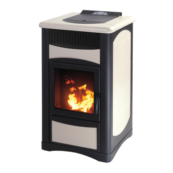
- Page 7 Product size and construction features We show below the main dimensions of the pellet heater, both in the air and in the water version. ERGOFLAM AIR: Typical Dimensions (Air) Height 1042 mm Width 580 mm Depth 580 mm Weight 250 kg Fume outlet diameter 80 mm Air intake diameter...
- Page 8 ERGOFLAM IDRO: Typical Dimensions (Water) Height 1042 mm Width 580 mm Depth 580 mm Weight 250 kg Fume outlet diameter 80 mm Air intake diameter 60 mm Water pipe diameter ¾” Tank capacity 28 kg Boiler capacity 10 l Page | 7...
- Page 9 Product technical features Our products are in conformity with EN 13240/2001 (solid-fuel household equipment) and subsequent amendments, and already in line with the draft of European standard EN 14785 (pellet-heating household equipment). They are also in accordance with legal provisions, that incorporate the following directives: 89/336 EEC (EMC directive) and subsequent amendments;...
- Page 10 Below is a short and simple note on the main performances and fittings of our product: ERGOFLAM AIR: PERFORMANCE Rated thermochemical capacity [kW] 11.5 Overall capacity [kW] 10.4 Working capacity [kW] Power requirements [kW] Start-Up 310.5 Rated 155.5 Combustion gas temperature ºC Mass flow of gases burnt [g/s]...
- Page 11 ERGOFLAM IDRO: PERFORMANCE Rated thermochemical capacity [kW] 14.5 Overall capacity [kW] Working capacity [kW] 10.3 Power requirements [kW] Start-Up 310.5 Rated 60.5 Maximum working water pressure [bar] Combustion gas temperature ºC Mass flow of gases burnt [g/s] Minimum draught [Pa] CO values [%] <...
- Page 12 The results in the table were obtained using certified pellet based on Austrian and German standards DIN 51731, DIN PLUS and ÖNORM M 7135. You are reminded that the ESC (European Standardisation Committee) is in the process of defining future European technical standards that will govern both the technical features of this fuel and the economic and environmental aspects associated with the production line.
- Page 13 Fuel features The main feature of this heater is that it burns a natural fuel (the pellet) obtained in an environmentally-friendly way from scraps of the timber industry (wood chippings, sawdust, etc.). Wood chippings and sawdust from wood products, after having been duly recleaned and dried, are compacted in state-of-the-art very high-pressure plants, into pure rounded wood pieces: the pellet.
- Page 14 The pellet, as also stipulated by current Italian legislation governing the commercial technology characteristics of fuels (DPCM 2.10.1995) must be produced exclusively with untreated wood chippings, with no other added materials. It is strictly prohibited to use any solid or liquid fuel other than the pellet to feed the stove.
- Page 15 Your local Building Control Officer would be happy to advise should questions arise regarding the requirements of the regulations. Olivieri products should be fitted by a HETAS approved installer, or approved by your local Building Control Officer. A faulty installation could cause danger to the inhabitants and structure of the building.
- Page 16 2.1 Indoor positioning Our product, both in the AIR and the IDRO version, is a heater that draws air that is necessary for its combustion process directly from the environment to be heated. For this reason and for the even more important reason of safety for the people using it, the heater must be installed in a sufficiently ventilated place in order to guarantee a continuous flow of air at all times.
- Page 17 1.They must have a clear space of not less than cm2; 2.They must be made at a height close to the floor; 3.They must be suitably protected by a wire mesh or grille in such a way that the minimum passage space is not and may not be reduced; 4.They must be placed in such a way that they are not obstructed in any way.
- Page 18 Having placed the outermost overall part of the heater at a distance of 80 cm from combustible and/or flammable material, if this distance cannot be maintained it is useful to arrange for heat protection to be provided . Do not get close to, and above all do not touch with flammable material the outer surfaces of the combustion chamber that, after continuous product use, may reach high temperatures (See Section 2 INSTALLATION) If the floor is made of combustible material (eg.
- Page 19 2.2 Fume extraction flue features The main features characterising the fume extraction flue are given. They are based on what is set out in standards (See Section 2 INSTALLATION) Inspection valves (I); Maximum height of the pipe directly connected to the heater fume extraction outlet must be between 2 - 3 m;...
- Page 20 Figure 2.3: Fume extraction flue In the room where the heat generator must be installed, there must be no fume- extraction hoods already in existence or installed, in order to avoid depressing the atmosphere. The air vents must not be closed. Keep the flue clean, performing a cleaning operation at least once a year;...
- Page 21 2.2.1 Outside wall extraction One of the installation solutions that may be adopted is that of placing the pellet heater close to an outside wall of the room so that the fumes are extracted directly to the outside (figure 2.4). Always guarantee that there is an inspection valve (I) that will allow effective and periodic cleaning to be carried out, and any condensation formed to be eliminated;...
- Page 22 Pellet combustion fumes may be extracted also using a pre-existing traditional flue (figure 2.5), provided that it is made to standard (see ). Below is a short list of some of the main features given in the standard that characterise a good chimney (C): Suitable insulation and proofing particularly in its outer section that is exposed to the weather;...
- Page 23 In the case where there are larger sections, it is necessary to insert a steel pipe (A) inside the masonry one (C), as shown in figure 2.6. The steel flue pipe must be suitable insulated with a high temperature- resistant rock wool or vermiculite material (B). Figure 2.6: Example of extraction flue connection.
- Page 24 In order to be able to operate, our heater ERGOFLAM IDRO must be suitably connected to a heating system. For this type of installation also, some simple suggestions are provided that will undoubtedly be helpful when installing the...
- Page 25 Power Line Delivery Return Mains Water The drainage cock (10) is placed at the lowest point of the water circuit. Page | 24...
- Page 26 WATER CONNECTION DIAGRAM: Heater Expansion Box Open Electronic Control Panel (inside heater) Circulator Outlet Pipe Safety Pipe Delivery of hot water for heating Return of water for heating System Inlet Cock System Drainage Cock Ball Valve Overflow Outlet T- Junction Inlet Pipe System Drainage Page | 25...
- Page 27 The ball valve mounted on the inlet pipe must be open in normal system operating conditions in order to allow water to be added to the boiler. It may be closed when it is necessary to drain the system. For connections of the various parts shown in the diagrams, please read the following paragraph carefully.
- Page 28 By way of example, the diagram setting out installation in a gas boiler system is also given. Power Line Delivery Return Mains Water To 3-way valve To Valve Control The drainage cock (10) is placed at the lowest point of the water circuit. Page | 27...
- Page 29 WATER CONNECTION DIAGRAM: Heater Expansion Box Open Electronic Control Panel (inside heater) Circulator Outlet Pipe Safety Pipe Delivery of hot water for heating Return of water for heating System Inlet Cock System Drainage Cock Ball Valve Overflow Outlet T- Junction Inlet Pipe System Drainage Gas Boiler...
- Page 30 2.4 Control board wiring diagram For general purposes, the diagram of the control board input and output connections is given. This diagram is expressly intended for the technical personnel in charge of installation and maintenance. The diagram given is valid for both the AIR and the IDRO version; obviously, in the former case, PIN 11 and 12 will not be used, as there will be no pump, whereas in the latter case, PIN 5 and 6 will not be used, as there will be no ambient fan.
- Page 31 Screw Pellet Tank Fume Extractor Therm Pressur Fume stat Gage circulati All- heat Equipotential Radio Receiv Radio RSIA Serial RJ45 Display Boile Ambien Display Fume temp Fume Extractor Page | 30...
- Page 32 Control board wiring diagram: 220 Vac Line Fume Extractor Screw Lamp Recirculating Pump Unused Pellet Safety Pressurestat High Voltage Safety Low Voltage Ambient Probe Fume Probe Boiler Probe Ext. Chrono White, Black, Red Page | 31...
- Page 33 2.5 Instructions for mounting product covering The heater is supplied in two separate packs, one containing the product and the other containing the majolica tiles. For mounting the outer covering, simple instructions are provided: 1. Use a crosshead screwdriver. 2. Lift the right side panel, insert the top front majolica tile and replace the panel in the original position.
- Page 34 Door rear panel Door front majolica Figure 2.8: Removing the rear door panel 4. Remove the vent grille and display support on top of the heater. Then remove the screws shown in figure 2.9. Take care when moving the front support in order to avoid damaging or disconnecting the flat connecting cable between the board and the display.
- Page 35 Vent grille Display Figure 2.9: Removing the vent grille and display support Page | 34...
- Page 36 5. For some models it might be necessary to lift and move the sheet-metal top of the heater sideways in order to insert the side majolica tiles. See figure 2.10. Take care when moving the top in order to avoid damaging or disconnecting the flat connecting cable between the board and the display.
- Page 37 6. Insert the side majolica tiles taking care to place the bevelled side majolica tile last. See figure 2.11. Bevelled side majolica Side majolica Figure 2.11: Inserting side majolica tiles Replace the sheet-metal top in its original place if it was necessary to move it. Page | 36...
- Page 38 7. Place the shaped top majolica tiles by resting them on the reference rings, as shown in 2.12. LH shaped majolica tile RH shaped majolica tile Front shaped majolica Figure 2.12: Positioning shaped majolica tiles 8. After having inserted the side and top majolica tiles, replace the vent grille and the display support.
- Page 39 The table below gives a list of the general sizes and quantities (stated in brackets) of the tiles needed to cover the product. Majolica Tile Sizes ERGOFLAM IDRO ERGOFLAM IDRO [mm] (ERG 400) (ERG 410) Side 450x200 (6) 450x200 (6)
- Page 40 It is very easy to light the ERGOFLAM AIR, after having connected it to the household mains power supply, by pressing the ON/OFF button. The ERGOFLAM IDRO is lit in the same way, but this operation may be performed only after connecting the product to a suitable water system (see our directions for installation).
- Page 41 Having placed the outermost overall part of the heater at a distance of 80 cm from combustible and/or flammable material, if this distance cannot be maintained, arrangements should be made to provide heat protection (UNI 7129, UNI 10683). In order to prevent the occurrence of malfunctions that could in turn be a source of possible damage to persons or property, we recommend avoiding lighting...
-
Page 42: Control Panel
Control panel ERGOFLAM AIR BUTTONS FUNCTION DESCRIPTION ON/OFF Pressed for around three seconds it allows the heater to be lit and extinguished. UNLOCKING Kept pressed it permits the heater to be unlocked and subsequently turned off (Errors in operation may cause the heater to lock). ENABLING Enabling of the timer-thermostat programmings within the timer menu. - Page 43 DAILY It is lit when the daily programming mode is set (TIMER daily) WEEKLY It is lit when the weekly programming mode is set (TIMER weekly) WEEK It is lit when the weekend programming mode is set (TIMER wkend). LAMP/ON It is lit when the lamp is in operation.
- Page 44 ERGOFLAM IDRO BUTTONS FUNCTION DESCRIPTION ON/OFF Pressed for around three seconds it allows the heater to be lit and extinguished. UNLOCKING Kept pressed it permits the heater to be unlocked and subsequently turned off (Errors in operation may cause the heater to lock).
- Page 45 Ambient temperature [ºC] Fume extractor speed [rpm] Software version DAILY It is lit when the daily programming mode is set (TIMER daily) WEEKLY It is lit when the weekly programming mode is set (TIMER weekly) WEEK It is lit when the weekend programming mode is set (TIMER weekend).
- Page 46 The method of setting the ambient thermostat for ERGOFLAM IDRO is activated through access to the menu mode. In the thermostats menu (TerM) the variable T 01 is the pump deactivation temperature and T 02 is the target ambient temperature.
- Page 47 During the check-up, errors may be indicated that prevent the heater starting up (point 3.4). For lighting on subsequent occasions, point 5 need not be performed. Extinguishing the product: 1. Press the ON/OFF button for several seconds. The heater will initiate the extinguishing procedure according to the methods set during the design stage (the extinguishing time is variable and may go from a minimum of a few minutes up to around 35 minutes).
- Page 48 The user is now able to manage the product’s operating power. On the display will appear the time schedule, the operating power, the ambient temperature (ERGOFLAM AIR) or the temperature of the water in the boiler (ERGOFLAM IDRO). Page | 47...
- Page 49 “Mod”). The condition of modulation is obtained if the ambient temperature reaches that set or if the boiler temperature reaches that programmed for this size (ERGOFLAM IDRO). At the modulation stage the product operates at power one regardless of the power programmed.
- Page 50 SUMMARY TABLE OF CONDITIONS FOR USE: OPERATING APPEARANCE ON DISPLAY CONDITION CHECK-UP “Chec” LIGHTING “Acc” STABILISATION “Stab” LIGHTING RECOVERY “Rec” NORMAL Display of time, level of operating power and ambient temperature, or temperature of the water in the boiler. MODULATION “Mod”...
- Page 51 Safety devices The heater is fitted with some safety devices, such as: The fume temperature detector probe: This device allows the fume temperature to be read and the effective operation of the product to be monitored continuously; The pellet tank temperature detector probe: It detects the tank temperature continuously and causes product operation to be locked if a certain safety limit value is exceeded;...
- Page 52 Message on Meaning Possible causes Possible remedies Display Er 01 Pellets tank thermostat safety High temperature Check that air intakes operation inside body of heater are not obstructed Probe malfunction Ambient temperature too high (insufficient cooling inside heater) Contact assistance centre Er 02 Pressure switch Safety...
- Page 53 “TERM” (THERMOSTAT): this enables the thermostat for ambient temperature and the thermostat for the temperature of the water in the boiler to be set. It is a menu that can be seen by the user only in ERGOFLAM IDRO. Page | 52...
- Page 54 TIMER MENU In the field of the timer menu it is possible to programme the heater daily, weekly or for the weekend, that is to say it is possible to choose a heater programming that is the same from Monday to Friday and a different one for Saturday and Sunday.
- Page 55 The top display now shows the time-schedule on 00:00 and on the last value set. Press the SET button to access the modify mode and use the POWER + and POWER - buttons to choose to change the hours or the minutes. Changing these values is done by pressing the TEMPERATURE + and TEMPERATURE - buttons.
- Page 56 Programming the Weekly Timer: Press the MENU button, scroll through the various menus by means of the power regulating buttons and finally access the timer menu by pressing the SET button. By means of the POWER + and POWER - buttons, display the message “sett” and press the SET button again.
- Page 57 After having set the time-schedule intervals, in order to activate the programming it is essential to proceed to enable it (operation of the weekly led being lit). Press the TIMERTHERMOSTAT/ESC button to exit the weekly timer menu at any time without saving the changes made. Scrolling through the minutes is done in the same way as described in the daily programming.
- Page 58 The top display now shows the time-schedule on 00:00 and on the hour previously set. Press the SET button to access the modify mode and use the POWER + and POWER - buttons to choose to change the hours or the minutes. Changing these values is done by pressing the TEMPERATURE + and TEMPERATURE - buttons.
- Page 59 METHODS MENU This menu allows the user to be able to choose between four different methods of product operation preset inside the board and described in detail at the beginning of this paragraph. Programming the methods menu: Press the MENU button, scroll through the various menus using the power regulating buttons and finally enter the fuel methods menu by pressing the SET button.
- Page 60 THERMOSTATS MENU (these can only be displayed in the ERGOFLAM IDRO version) This allows the temperatures of the boiler pump and ambient thermostats to be set. The boiler pump thermostat is identified with the code t01 and can be set between a minimum of 5ºC and a maximum of 85ºC.
- Page 61 One-way radio control Through this radio control, that has a range of action of 10 metres, it is possible to regulate some heater operating parameters. Off button On button Operating power decrease button Operating power increase Figure 3.1: Radio control With this radio control, it is in fact possible to light and extinguish the heater as well as regulate the operating power levels.
- Page 62 MAINTENANCE Scheduled maintenance It is necessary to perform periodic maintenance of the heater in order to ensure constantly correct and effective operation. The cleaning operations described below must be carried out only when the heater is totally cold and disconnected from the household mains power supply.
- Page 63 The ash drawer at the base of the pan must be cleaned every time the fire is lit, whereas the “ash box” may be emptied when full. Figure 4.2: Ash tray. Figure 4.3: Ash box. It might be necessary, at regular intervals, to clean the glass because it inevitably becomes dirty.
- Page 64 By cleaning the surfaces of the exchanger pipes, the best possible heat exchange is always guaranteed. Figure 4.5: Tie-rods The frequency with which to perform the scraping operations depends, as in the case of cleaning the glass, on the intensity of use of the apparatus. In normal usage conditions (eight hours a day), we recommend this operation be performed at weekly intervals.
- Page 65 Yearly maintenance We recommend performing a more thorough and precise maintenance of the apparatus once every season. All the maintenance operations to be performed on a yearly basis need to be carried out with the heater cold and disconnected from the household mains power supply.
- Page 66 In order to be able to reach the compartment, simply remove the cover that is just behind the box by releasing the two nuts (wing-nuts). ERGOFLAM IDRO In this model the area of the set of pipes can be reached from openings placed at the rear of the apparatus, and access is gained also by removing the cast iron plate of the combustion chamber.
- Page 67 It is advisable to perform the cleaning in the above-mentioned areas with the help of the cleaning-rod provided or a vacuum cleaner. At the end of the winter, we recommend emptying the fuel tank of residue pellet and storing it according to the methods suggested in chapter one. We recommend a thorough cleaning of both the flue and the fume junction (at least once during the whole operating season) in order to prevent fire risks.
- Page 68 Now it is possible to perform the cleaning, using the brush. ERGOFLAM IDRO The side slits are also present in the ERGOFLAM IDRO version (two on each side) and can be reached as described above for the air version. Every 2 years it is necessary to clean the steel fan of the fume extractor and its housing.
- Page 69 Troubleshooting This paragraph has been designed to give the purchaser of our product a quick and effective means of understanding any problems that may arise when using the heater. If these possible solutions do not apply to the operating defect you have experienced, please call the customer service centre for further information.
Need help?
Do you have a question about the ERGOFLAM IDRO and is the answer not in the manual?
Questions and answers