Xerox Phaser 7400 Service Manual
Color printer
Hide thumbs
Also See for Phaser 7400:
- User manual (196 pages) ,
- Service manual (109 pages) ,
- Evaluator manual (20 pages)
Table of Contents
Advertisement
Quick Links
Advertisement
Table of Contents
Troubleshooting

Related Manuals for Xerox Phaser 7400


Summary of Contents for Xerox Phaser 7400
- Page 1 Phaser 7400 ® color printer Service Manual Book 1: Print Engine...
-
Page 3: Phaser 7400
® Phaser 7400 Color Printer Service Manual Book 1: Print Engine Warning The following servicing instructions are for use by qualified service personnel only. To avoid personal injury, do not perform any servicing other than that contained in the operating instructions, unless you are qualified to do so. - Page 4 Copyright © 2005 Xerox Corporation. All Rights Reserved. Unpublished rights reserved under the copyright laws of the United States. Contents of this publication may not be reproduced in any form without permission of Xerox Corporation. Copyright protection claimed includes all forms of matters of copyrightable materials and information now...
-
Page 5: Service Terms
Service Terms Manual Terms Various terms are used throughout this manual to either provide additional information on a specific topic or to warn of possible danger present during a procedure or action. Be aware of all symbols and terms when they are used, and always read NOTE, CAUTION, and WARNING statements. -
Page 6: Symbols Marked On The Product
30 minutes. 30 min. Avoid pinching fingers in the printer. Use caution to avoid personal injury. Use caution (or draws attention to a particular component). Refer to the manual(s) for information. Phaser 7400 Color Printer Service Manual... -
Page 7: Power Safety Precautions
Power Safety Precautions Power Source For 115 VAC printers, do not apply more than 135 volts RMS between the supply conductors or between either supply conductor and ground. For 230 VAC printers, do not apply more than 254 volts RMS between the supply conductors or between either supply conductor and ground. -
Page 8: Electrostatic Discharge (Esd) Precautions
Handle IC’s and EPROM’s carefully to avoid bending pins. Pay attention to the direction of parts when mounting or inserting them on Printed Circuit Boards (PCB’s). Phaser 7400 Color Printer Service Manual... -
Page 9: Service Safety Summary
Service Safety Summary General Guidelines For qualified service personnel only: Refer also to the preceding Power Safety Precautions. Avoid servicing alone: Do not perform internal service or adjustment of this product unless another person capable of rendering first aid or resuscitation is present. Use care when servicing with power: Dangerous voltages may exist at several points in this product. -
Page 10: Servicing Electrical Components
This printer uses heat to fuse the toner image to media. The Fuser is VERY HOT. Turn the printer power off and wait at least 5 minutes for the Fuser to cool before you attempt to service the Fuser or adjacent components. viii Phaser 7400 Color Printer Service Manual... -
Page 11: Regulatory Specifications
Consult the dealer or an experienced radio/television technician for help. Any changes or modifications not expressly approved by Xerox could void the user's authority to operate the equipment. To ensure compliance with Part 15 of the FCC rules, use shielded interface cables. -
Page 12: European Union
This is a class A product. In a domestic environment this product may cause radio interference in which case the user may be required to take adequate measures. Xerox Corporation declares, under our sole responsibility, that the product to which this declaration relates is in conformity with the following standards and other... -
Page 13: Manual Organization
Manual Organization The Phaser 7400 Color Printer Service Manual is the primary document used for repairing, maintaining, and troubleshooting the printer. The manual is organized into two books. This volume, Book 1, focuses on the print engine with the exception of providing complete diagnostic and troubleshooting procedure for the printer and all its options. - Page 14 Section 6 - Parts Lists: This section contains exploded views of the option FRUs, as well as FRU part numbers. Section 7 - Wiring Diagrams: This section contains option plug/jack locations and wiring diagrams. Phaser 7400 Color Printer Service Manual...
-
Page 15: Table Of Contents
Contents Service Terms ..........iii Symbols Marked on the Product . - Page 16 2 Theory of Operation Phaser 7400 Operational Overview ......2-2 Imaging Unit ........2-3 LED Heads .
- Page 17 Chassis Assemblies ........2-46 Basket Assembly.
- Page 18 Metered Toner Is not Enabled ......3-69 Replace Metered [C][M][Y][K] Toner Cartridge ... . . 3-70 Phaser 7400 Color Printer Service Manual...
- Page 19 Tray and Media Errors ........3-71 Clear Tray 1 (MPT) Riser Plate .
- Page 20 Tray 2 Lift Motor Failure ......3-159 xviii Phaser 7400 Color Printer Service Manual...
- Page 21 Waste Cartridge is Almost Full ......3-180 Non-Xerox [C][M][Y][K] Toner Cartridge ....3-181 Staple Cartridge Is Empty .
- Page 22 Scan Direction Dark Streaks ......5-37 Process Direction Bands, Voids, or Streaks....5-38 Phaser 7400 Color Printer Service Manual...
- Page 23 6 Adjustments and Calibrations Calibrations ..........6-2 Color Calibration .
- Page 24 Fuser Exit Sensor and Actuator ......8-71 Top Output Tray Stack Full Sensor..... . . 8-72 xxii Phaser 7400 Color Printer Service Manual...
- Page 25 Side Output Tray Detect Sensor ......8-73 Side Output Tray Stack Full Sensor..... . . 8-75 Door E Detect Sensor .
- Page 26 Print Engine Parts ......... . 9-4 Xerox Supplies and Accessories ......9-58 Service Kits .
- Page 27 Phaser 7400 Menu Map ........
- Page 28 Phaser 7400 Color Printer Service Manual...
-
Page 29: General Information
General Information In this chapter... Printer Introduction and Overview Printer Configurations Parts of the Printer Printer Options Specifications Section... -
Page 30: Printer Introduction And Overview
Printer Introduction and Overview The Xerox Phaser 7400 Color Printer Service Manual is the primary document used to repair, maintain, and troubleshoot this printer. For manual updates, Service Bulletins, knowledge base, etc., see www.xerox.com/office/7400support. For further technical support, contact your assigned Xerox Technical Support for this product. -
Page 31: Printer Configurations
Printer Configurations The Phaser 7400 Color Printer is available in five configurations. The main differences are standard memory, optional high-capacity feeders, duplexing (2-sided printing) capabilities, networking, and internal Hard Drive. The following table lists the available configurations. Printer Configuration Features... -
Page 32: Metered Printing
When replacing the Engine Control Board from a metered printer, exchange NVRAM devices or use the Save/Restore utilities in Service Diagnostics to preserve the NVRAM settings. The Mode and PIN-entered values are not affected by NVRAM reset utilities. Phaser 7400 Color Printer Service Manual... -
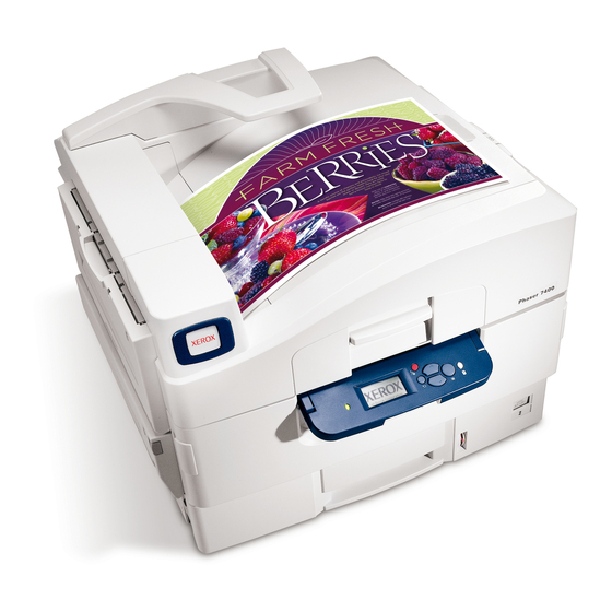
Page 33: Parts Of The Printer
Parts of the Printer Front View 7400-001 1. Top Cover latch 6. Paper Catcher 2. Control Panel 7. Top Output Tray 3. Tray 2 8. Door A 4. Front Door 9. Tray 1 (MPT) 5. Level Indicator 10.Door B General Information... - Page 34 Rear View 7400-002 1. AC Receptacle 6. USB Port 2. Door D 7. Ethernet Port 3. Door E 8. Serial Debug Port 4. Side Output Tray 9. Mode Select Port 5. Power Switch 10.Rear Cover Phaser 7400 Color Printer Service Manual...
-
Page 35: Control Panel
Control Panel The Control Panel contains one tricolor LED, a display window, and six function buttons. These buttons navigate the menu system shown on the display, perform various functions, and select operational modes for the printer. LED Indicators: LED State Printer State Green Ready to Print... -
Page 36: Image Processor Board
Image Processor Board Transfer the following components, if installed, to the new board when replacing the Image Processor Board. Configuration Card NVRAM Hard Drive Memory (RAM) s7400-352 Phaser 7400 Color Printer Service Manual... -
Page 37: Printer Options
Printer Options Phaser 7400 Color Printer options include: 20 GB Hard Drive Additional Memory 550-Sheet Feeder (LTA) 1650-Sheet Feeder (HCF) Duplex Unit 1,000-Sheet Finisher (with hole punch, staple, saddle-stitch, and offset) Hard Drive A 20 GB Hard Drive is available to enable the Job Collation, Saved Jobs, Proof, Personal, and Secure Print options. -
Page 38: Configuration Card
HCF and printer. Electrical connection to the printer is made by a single interface connector. s7400-001 1650-Sheet Feeder The 1650-Sheet Feeder adds three 550-sheet trays. Control signals reach the sheet feeder by a single connection. s7400-003 1-10 Phaser 7400 Color Printer Service Manual... -
Page 39: Duplex Unit
Duplex Unit The Duplex Unit adds two-sided printing. The Duplex Unit is inserted into the printer’s left side just below the Side Output Tray. Electrical connection is made by an interface connector located inside the Duplex Unit cavity. s7400-305 Finisher The Finisher increases the output capacity of the printer by 1,000 sheets. -
Page 40: Maintenance Items
A maintenance item is a printer part or assembly that has a limited life, and requires periodic replacement. Fuser Transfer Belt Imaging Unit Waste Toner Reservoir s7400-307 Consumables Consumables consist of the four toner cartridges used in the printer. Toner Cartridge s7400-308 1-12 Phaser 7400 Color Printer Service Manual... -
Page 41: Specifications
Specifications Memory Specifications Characteristic Specification Minimum RAM 256 MB Maximum RAM 1 GB Supported RAM SODIMM 200-pin module of 256 or 512 MB. All combinations are allowed for configurations of 256, 512, 768 MB, and 1 GB. NVRAM Single chip of either PPROM or StrataFlash 16 MB Consumable Life Specifications Internal counters track Consumables and Maintenance Items life usage. -
Page 42: Electrical Specifications
16 kg (36 lb.) Finisher Value Height: 101.6 cm (40.0 in.) Width: 81.3 cm (32.0 in.) Depth: 59.5 cm (23.6 in.) Weight: 55 kg (122 lb.) Surface Value Tilt tolerance: Within 50 mm side to side. 1-14 Phaser 7400 Color Printer Service Manual... - Page 43 Minimum Clearances 61.0 cm (24 in.) 50.8 cm 15.2 cm (6 in.) (20 in.) 50.8 cm (20 in.) 50.8 cm (20 in.) 127.5 cm (50 in.) 167.4 cm (66 in.) 61.0 cm (24 in.) 68.5 cm (27 in.) 15.2 cm (6 in.) 50.8 cm (20 in.) 50.8 cm...
-
Page 44: Functional Specifications
Tray 4 Tray 5 Tray 6 Monochrome 12.0 13.5 Color 15.5 16.5 17.5 18.5 *These conditions apply to the values in the table above: Printer at Ready A4 LEF paper Plain paper mode 1-16 Phaser 7400 Color Printer Service Manual... -
Page 45: Image Specifications
Image Specifications Characteristic Specification Maximum Print Area Minimum margins = 5 mm (0.2 in.) on all sides Maximum paper size = 328 mm x 1200 mm (12.9 in.x 47.25 in.) Minimum paper size = 105 mm x 148 mm (4.13 in. x 5.83 in.) Guaranteed Print Area The printer prints images meeting the Print Quality Specification except the margin area, which is 5.0 mm inside each edge of... -
Page 46: Media And Tray Specifications
Tray 1 Only 210 x 297 mm (8.27 x 11.69 in.) Tray 1 Only Tray Universal Tray Tray 1 (MPT) Capacity Standard Paper 550 Sheets 100 Sheets Transparency 100 Sheets 50 Sheets Envelopes 10 each 1-18 Phaser 7400 Color Printer Service Manual... - Page 47 Media and Tray Specifications Specification Trays Supported Type Weight Media Types Plain Paper 65 - 90 g/m (17 - 24 lb. Bond) All Trays and Weights Heavy Plain Paper 85 - 120 g/m (22 - 32 lb. Bond) All Trays Thin Card Stock 100 - 163 g/m (30 - 60 lb.
- Page 48 1-20 Phaser 7400 Color Printer Service Manual...
-
Page 49: Theory Of Operation
Theory of Operation In this chapter... Overview Printer Controls Paper Path of the Printer Major Assemblies and Functions Section... -
Page 50: Phaser 7400 Operational Overview
Phaser 7400 Operational Overview The Phaser 7400 Color Printer is a full-color LED printer using electrophotographic recording principals to place a full color image onto the print media. The system, as it appears in the following illustration, contains four Imaging Units comprised of a... -
Page 51: Imaging Unit
Imaging Unit The function of each Imaging Unit component is listed in the following table. Imaging Unit Components Component Function Drum The Drum is an aluminum cylinder coated with a layer of photo- conductive material that retains electrical charges on its surface until exposed to light. -
Page 52: Led Heads
Heat Roller. This pressure bonds the melted toner to the paper. Heater Lamps The Heater Lamps are quartz glass tubes containing heater coils. The Heater Lamps heat the Heat Roller. Phaser 7400 Color Printer Service Manual... -
Page 53: Transfer Unit
Fuser Components (Continued) Component Function Temperature Sensors These are Thermistors having a known value of resistance that varies with temperature. The sensors monitor the surface temperature of the Heat and Pressure Rollers. Thermostats The Thermostats provide a second-level of protection. If the Heat or Pressure Roller temperature exceeds the target temperature, AC power is cut-off to the Heater Rods. -
Page 54: Print Process Summary
(5) Fusing (9) Waste Toner Recovery (8) Exit Top Output Tray Side Output Tray s7400-383 Refer to the Print Process Block Diagram above to relate each of the following process steps to an individual component. Phaser 7400 Color Printer Service Manual... - Page 55 1. Charging: The charge roller (RTC) is negatively charged by the High-Voltage Power Supply (HVPS) and is kept in contact with the drum surface to provide a uniform negative charge on the drum as it rotates at a constant speed. This occurs simultaneously for CMYK.
- Page 56 Transfer Unit, is applied to the Transfer Roller attracting the negatively-charged toner from the surface of the drum onto the paper. Drum Paper Transfer Unit Belt Transfer HVPS Roller s7400-020 Phaser 7400 Color Printer Service Manual...
- Page 57 5. Fusing: The Fuser uses a combination of heat and pressure to bond the toner image to the paper. Thermostat Thermistor Paper Heat Roller Pressure Roller Fuser Belt Thermistor Thermostat s7400-021 6. Transfer Unit Cleaning: Toner remaining on the Transfer Unit belt is removed by a cleaning blade and transported by Auger to the toner waste port.
-
Page 58: Printer Controls
Color Registration Sensors are mounted inside the Registration Sensor Assembly. These sensors are positioned at the front and rear edges of the Transfer Unit belt as shown in the following figure. 2-10 Phaser 7400 Color Printer Service Manual... - Page 59 LED Head Imaging Unit Drum Transfer Unit Belt Belt Running Direction Cleaning Blade Color Registration Sensor Cleaning Blade Transfer Belt Color Registration Front Sensor Belt Running Direction Color Registration Rear Sensor (Transfer Unit as seen from below) s7400-041 The Color Registration Sensors are used to measure the amount of misalignment based on the position of the color patches in relation to the black toner patch that precedes them.
- Page 60 The image write timing is changed to compensate for any registration shift. Color registration is checked when the power is turned On, a cover is closed, the printer is idle for more than 2 hours, or after printing 400 sheets. 2-12 Phaser 7400 Color Printer Service Manual...
-
Page 61: Automatic Density Control
550-Sheet Feeder is identified as Tray 3. If both optional feeders are installed, the 550-Sheet Feeder tray is identified as Tray 3, and the trays of the 1650-Sheet Feeder are identified as Trays 4, 5, and 6. Note The Phaser 7400 printer supports a maximum of 4 optional trays. Theory of Operation 2-13... -
Page 62: Image Transfer Control
Control Panel. No further jobs are accepted. All printer CRCs wait for the current print job to finish before declaring a Low or Empty state. 2-14 Phaser 7400 Color Printer Service Manual... -
Page 63: Sensors
Sensors The printer contains sensors of various types that perform a variety of functions. One group of sensors track the progress of the paper along the paper path, and detect if a paper jam occurs. Other sensors detect the presence of the Toner Cartridges, stop printer activity if a door is open (interlock), detect the presence and size of media in the trays, and monitor the fusing temperature. - Page 64 Interrupts AC power to the Fuser. Offset Home Photo-receptive Detects Offset carriage position. Temp/Humidity Integrated circuit Monitors the printer’s environment. Waste Toner Hall-effect Monitors waste augers and transfer belt. CRUM antenna RFID code reader Communicates with the CRUMs. 2-16 Phaser 7400 Color Printer Service Manual...
-
Page 65: Sensors In The Printer
Sensors in the Printer The following illustrations identifies the location of each sensor. Toner Supply CM Sensor Color Registration Sensors Low Toner Sensors Toner Supply YK Sensor Imaging Unit Up/Down Sensor Waste Toner Auger Rotation Sensor Waste Toner Reservoir Auger Rotation Sensor Drum Phase Sensors ADC Sensor Waste Toner Reservoir Full Sensor... - Page 66 Registration Sensor #1 MPT Level Sensor Feed Out OHP Sensor Sensor #2 MPT No Paper Sensor Tray 2 Level Sensor No Paper Sensor #2 Registration Sensor #2 Tray 2 Low Paper Sensor s7400-588 2-18 Phaser 7400 Color Printer Service Manual...
-
Page 67: Sensor Functions
Sensor Functions The following table lists the function of each sensor. Sensor Functions Sensor Function Sensor State Top Output Tray Detects the Top Output Tray stack height. On: not full Stack Full Sensor Off: full Side Output Tray Detects the Side Output Tray stack height. On: not full Stack Full Sensor Off: full... - Page 68 Detects media at the universal tray’s Registration On: media present Registration Sensor Roller. Off: media absent Feeder Detects the lift position of media in the universal On: media present Level Sensor trays. Off: media absent 2-20 Phaser 7400 Color Printer Service Manual...
-
Page 69: Paper Level Detection
Sensor Functions (Continued) Sensor Function Sensor State Feeder Detects media leaving the universal tray’s Feed On: media present Feed-Out Sensor Rollers. Off: media absent Feeder Detects the absence of media in the universal trays. On: media present No Paper Sensor Off: media absent Feeder Detects a low condition of media loaded in the... -
Page 70: Paper Size Detection
Universal Tray Paper Size Switch States Media Size No tray installed A/Letter (LEF) A/Letter (SEF) A3-Nobi A4 (portrait) A4 (landscape) B5 (LEF) B5 (SEF) B/Tabloid Executive Ledger 13 in. Legal 14 in. s7400-645 2-22 Phaser 7400 Color Printer Service Manual... -
Page 71: Jam Detection
Jam Detection The printer checks for a paper jam when the printer is powered on and during printing. When a paper jam occurs, printing immediately stops. Below is a diagram of jam locations within the printer. Media Jams occur in the paper path if the associated sensor does not turn On within a specified amount of time, meaning the jam occurs prior to reaching the sensor, or if the sensor does not turn Off within a specified amount of time, meaning the jam occurs along the path of the sensor. -
Page 72: Interlock Detection
Agitation Bar target remains at its highest point is reduced. This change in Agitation Bar timing signals toner level changes. OFF Time (Minimum Height) ON Time (Maximum Height) Low Toner Sensor Target Board Agitation Bar s7400-173 2-24 Phaser 7400 Color Printer Service Manual... - Page 73 Toner Full State When the Imaging Unit is at a toner full state, the Agitation Bar target remains at its maximum height for a period exceeding .85 seconds. Periods in excess of .85 seconds indicate a toner full state. Periods below .85 seconds indicate at toner low state. Agitation Bar Target Toner Full: 100g...
- Page 74 Cartridge is low. Once this condition is recognized, the Toner Low warning message for the appropriate color is displayed after the printing of an equivalent of 5% coverage for 200 A sized sheets. At this point, the Toner Cartridge is considered empty. 2-26 Phaser 7400 Color Printer Service Manual...
-
Page 75: Input Paper Path
Input Paper Path Paper is transported through the printer along the paper path shown below. Fuser Registration Exit Rollers Roller #1 Tray 1 (MPT) Feed Roller Duplex Entrance Roller Tray 2 Registration Roller #2 Transfer Tray 3 Duplex Unit Belt Transport Rollers Tray 4... - Page 76 Pick Roller Feed-Out Sensor #1 Retard Roller Registration Sensor #1 Transfer Unit Level Sensor Entrance Sensor Paper Registration Roller #1 Registration Clutch #1 No Paper Sensor Transport Roller Registration Motor Feed Motor s7400-171 2-28 Phaser 7400 Color Printer Service Manual...
- Page 77 The Tray 1 (MPT) Lift Plate should remain down (home position) when opened. It should only lift when media is sensed. However, the Tray 1 (MPT) Lift Plate is spring loaded. These springs are compressed under the Lift Plate by the Lift Arms driven by the Registration Motor.
-
Page 78: Paper Fed From Tray 2
The sheet is detected by the Transfer Unit Entrance Sensor and the Transfer Unit Motor rotates to drive the sheet through the Imaging Units. As the trailing edge of each sheet passes the Feed-Out Sensor, the Lift Motor lifts the next sheet to pre-feed position. 2-30 Phaser 7400 Color Printer Service Manual... - Page 79 Registration Roller #1 Transfer Unit Entrance Sensor Registration Sensor #1 Transport Rollers Registration Clutch #1 Registration Roller #2 Registration Clutch #2 Feed-Out Registration Sensor #2 Sensor #2 Feed Roller Pick Roller Paper Retard Roller Registration Motor Feed Motor s7400-026 Theory of Operation 2-31...
- Page 80 This motor lifts the tray’s base plate raising the media to the pre-feed position. Low Paper Sensor The actuator lowers as print media is used in the tray. When the actuator lowers to a pre-determined position, it blocks the sensor to trigger a low paper status. 2-32 Phaser 7400 Color Printer Service Manual...
-
Page 81: Paper Fed From Optional Trays
Paper Fed from Optional Trays The following describes the paper path as it is fed from the optional Tray 3. Trays 4 through 6 function in the same manner. Media moves along the paper path as follows: Paper loaded in the tray is detected by the Paper Size Switches. The tray’s Lift Motor rotates lifting the sheet to the pre-feed position detected by the Level Sensor. - Page 82 Detects presence of media in the tray based on the position of the Actuator. Paper Size Switches Detects media size using the position of the side and rear guides, and presence of the paper tray. 2-34 Phaser 7400 Color Printer Service Manual...
-
Page 83: Duplex Unit
Registration Motor This motor drives the Registration Rollers to pull media from the tray into the paper path. Registration Clutch This clutch transfers Registration Motor drive to the Registration Roller. Registration Roller This roller aligns the leading edge of the sheet to correct any skew. Registration Sensor This sensor detects media as it arrives at the Registration Rollers. - Page 84 Transport the media through the Duplex Unit and drive the sheet into the primary paper path. Duplex Motors One motor drives the Duplex Entrance Roller, the other drives the Transport Rollers using a series of belts. 2-36 Phaser 7400 Color Printer Service Manual...
-
Page 85: Output Paper Path
Output Paper Path The Phaser 7400 paper path for paper exiting the Fuser are: Directed by the Exit Gate to the Top Output Tray on the Top Cover (facedown). Directed by the Exit Gate to the Side Output Tray or Finisher. -
Page 86: Top Output Tray
Upper Tray. For Saddle stitching, the stack is drawn through the Stapler and stapled at the center point. The stapled stack continues through the Stapler and is folded in the Saddle Unit. The stapled and folded stack is delivered to the Lower Tray. s7400-386 2-38 Phaser 7400 Color Printer Service Manual... -
Page 87: Drive Assemblies
Drive Assemblies The following illustration shows the location for all the printer’s motors. Toner Motors Job Offset Motor Imaging Unit Motors Fuser Motor Registration Motor Duplex Motors Transfer Unit Motor Lift Motor Feed Motor Waste Toner Motor s7400-389 Imaging Unit Drive Motors The Imaging Unit Motors drive the Imaging Unit drums, toner Agitation Bars and Agitation Gears. - Page 88 C-ID Unit M-ID Unit Y-ID Unit K-ID Unit Lift Uplink C-ID Motor (CCW) ID Unit Operations During Monochrome Printing C-ID Unit M-ID Unit Y-ID Unit K-ID Unit Lift Uplink C-ID Motor (CW) s7400-172 2-40 Phaser 7400 Color Printer Service Manual...
-
Page 89: Transfer Unit Motor
Imaging Unit Drive The four Imaging Unit Motors supply the drive to the Imaging Unit drum and Agitation Bar and Gear as shown in the following figure. Imaging Unit Motor Imaging Unit Drum Agitation Gear Agitation Bar Imaging Unit s7400-390 Transfer Unit Motor The Transfer Unit motor turns clockwise driving the Transfer Unit belt. - Page 90 Transfer Unit Drive The Transfer Unit Motor supplies the drive to the transfer belt as shown in the following figure. Transfer Unit Motor Transfer Unit Gear Transfer Unit Belt Transfer Roller Transfer Unit s7400-391 2-42 Phaser 7400 Color Printer Service Manual...
-
Page 91: Fuser Motor
Fuser Motor The Fuser Motor drives the Fuser Heat and Pressure Rollers, as well as the Exit Rollers. This is shown in the following figure. Fuser Motor Heat Roller Pressure Roller Exit Rollers Fuser s7400-392 Theory of Operation 2-43... -
Page 92: Toner Dispense Motors
The CM and YK Toner Dispense Motors are mounted above the Imaging Unit Motors and drive the Toner Cartridge Supply Augers and Agitation Springs to deliver toner to the Imaging Units. Toner Dispense Motors s7400-48 2-44 Phaser 7400 Color Printer Service Manual... -
Page 93: Duplex Drive Motors
Duplex Drive Motors Two motors are used to capture and transport paper in the Duplex Unit. Duplex Motor A drives the Entrance Roller CCW to capture paper, then CW to drive the media into the Transport Rollers. Motor B uses a series of belts to drive the four Transport Rollers that move media to the Registration Assembly. -
Page 94: Chassis Assemblies
Assembly. The Lower Basket Assembly connects to the Upper Basket Assembly and supports the four Imaging Units and the Waste Toner Manifold. The Lower Basket sub-assembly, or the entire Basket Assembly are available as replacement parts. 2-46 Phaser 7400 Color Printer Service Manual... -
Page 95: Waste Toner Recovery
Waste Toner Recovery Waste toner recovery moves the toner collected from the Imaging Unit drums and Transfer Unit belt to the Waste Toner Reservoir located at the front of the printer. Driven by the Waste Toner Motor, separate Augers in the Waste Toner Manifold and Waste Toner Duct pull toner through a tube to the Waste Toner Reservoir. -
Page 96: Registration Assembly
Produces a signal that varies dependent on media thickness. Temperature/Humidity Sensor Monitors environmental conditions surrounding the printer. Front Sensor Board Communicates the status of Tray 1 (MPT) and Registration Assembly sensors to the Motor Driver Board. 2-48 Phaser 7400 Color Printer Service Manual... -
Page 97: Exit Assembly
Exit Assembly The Exit Assembly uses rollers, solenoids, sensors, and diversion gates to handle media exiting the Fuser. Exit Assembly s7400-396 Exit Assembly components include: Exit Gate The Exit Gate switches the paper path. When the Exit Gate is in its resting position, paper is fed to the Top Output Tray. - Page 98 Duplex Unit and returns it to the Registration Assembly for printing on side 2. The following figure shows the Duplex Gate linkage between the Duplex Unit and Exit Assembly 2-50 Phaser 7400 Color Printer Service Manual...
-
Page 99: Job Offset Assembly
Exit Assembly Duplex Unit s7400-407 Job Offset Assembly Job Offset Motor The Offset Motor acting through the Offset Gear shifts the media forward or backward providing offset capability. The flow diagram shows the components involved in the offset process. OFFSET MOTOR OFFSET GEAR OFFSET CHUTE OFFSET ROLLER... -
Page 100: Trays
Detects when transparency media is being fed to the Registration Assembly. Feed-Out Sensor #1 Door A Interlock Switch Level Sensor No Paper Sensor Pick Roller Retard Roller Feed Roller Tray 1 (MPT) Home Position Sensor s7400-399 2-52 Phaser 7400 Color Printer Service Manual... -
Page 101: Universal Trays
Tray 1 (MPT) incorporates a single set of guides to establish paper width. The time required for the paper to clear the No Paper Sensor identifies the paper’s length. When media is placed in Tray 1 (MPT), the leading edge strikes the actuator of the No Paper Sensor indicating the presence of paper. -
Page 102: Universal Feeder
Paper Support that rotates 180 degrees to support the stack, and a latching door for printers equipped with a Finisher. Stack level is monitored by The Side Output Tray Full Stack Sensor mounted in the Exit Assembly. 2-54 Phaser 7400 Color Printer Service Manual... -
Page 103: Electrical
Electrical The following provides an overview of the major electrical components. Additional detail is located in Section 10, Wiring Diagrams. LED Relay Board Registration Sensor Board CRUM Reader Board Front Sensor Board Rear Sensor Board CRUM Antenna Duplex Control Board Control Panel s7400-410 IP Board... -
Page 104: Control Panel
Registration Sensor Board Located in the Registration Sensor Assembly, the Registration Sensor Board includes the two sensors that monitor color registration. LED Relay Board Distributes power from the LVPS to the four LED Heads. 2-56 Phaser 7400 Color Printer Service Manual... -
Page 105: Imaging Unit Sensor Board
Imaging Unit Sensor Board The Imaging Unit Sensor Board communicates with the Engine Control Board and supplies voltage for the two Imaging Unit Fans and Fuser Fan. The board also includes the four Low Toner Sensors that monitor toner levels in the Imaging Units, and the Imaging Unit Position sensor that detects the position of the Lift Uplink. -
Page 106: Hvps
Developer Roller voltage -300 to -700V Sponge Roller voltage Drop from SB Output with Zener Cleaning Blade voltage 0 to 7kV Transfer Roller voltage (not shown) Ground Charge Roller Drum Developer Roller Sponge Roller s7400-337 2-58 Phaser 7400 Color Printer Service Manual... -
Page 107: Lvps
LVPS Supplies AC power from the power source to the Fuser heater. Generates and supplies stable low-voltage DC power (+5 VDC, and +24 VDC) to be used for the logic and other circuits within the printer. The LVPS includes the LVPS Board with attached Power Switch, the AC Harness, a Fan, and the box enclosure. -
Page 108: Fans
LVPS Fan located in the LVPS Duplex Unit Fan inside the Duplex Unit Fuser Fan Top Cover Fan IP Fan Duplex Fan Transfer Unit Fan Card Cage Fan LVPS Fan Imaging Unit Fan s7400-398 2-60 Phaser 7400 Color Printer Service Manual... -
Page 109: Solenoids And Clutches
Solenoids and Clutches A number of solenoids and clutches are used to actuate various gates and rollers. The figure below shows the position of all the solenoids and clutches in the Print Engine. Registration Clutch #1 Exit Gate Solenoid Duplex Gate Registration Clutch #2 Solenoid Registration Shutter Solenoid... - Page 110 2-62 Phaser 7400 Color Printer Service Manual...
-
Page 111: Error Messages And Codes
Error Messages and Codes In this chapter... Introduction Servicing Instructions Messages, Codes, and Procedures Section... -
Page 112: Introduction
Enter the printer’s IP address as the URL. Select the Support --> Troubleshooting --> Diagnostics Logs and the fault history displays. If additional information is required, print the Service Usage Profile from Troubleshooting --> Service Tools. Phaser 7400 Color Printer Service Manual... -
Page 113: Status Page
Status Page The Status page is a two-page report that provides general information about the printer, the consumables, the status of routine maintenance items, registration and color test patterns. The first page includes general information about the printer including firmware versions, page count, feature set, and consumables. Page 1 also provides color registration, calibration, and print target examples. -
Page 114: Servicing Instructions
2. Use the Disassembly Procedures to replace the part. Step 5 - Final Check Test the printer to be sure you have corrected the initial problem and verify there are no additional problems present. Phaser 7400 Color Printer Service Manual... -
Page 115: Messages, Codes, And Procedures
Messages, Codes, and Procedures This section correlates the output of the printer’s diagnostic aids and provides the troubleshooting procedure to locate and correct reported errors. Error Message Abbreviations Due to limited space, some error messages, procedures, or descriptions include abbreviations. The most common abbreviations used are listed here. Term Definition Comment... -
Page 116: Jam Locator
Refer to this diagram when questions arise regarding the area of the jam. Door H Door A Door G Door J Door B Door F Door I Front Door Door C Door E Door D s7400-484 Phaser 7400 Color Printer Service Manual... -
Page 117: Error Message Summary
Error Message Summary The Error Message Summary table lists possible errors, along with the corresponding code, and page reference for the corrective procedure. The Error column lists the error code for fatal or jam errors that appears in the Help text displayed by pressing the Help(?) button, listed on the printer Status page, or logged by the Service Usage Profile. - Page 118 3-61 Replace Waste Cartridge 3-62 Replace Fuser 3-63 Install or Reseat [C][M][Y][K] Toner Cartridge 3-64 Install or Reseat [C][M][Y][K] Imaging Unit 3-65 Install or Reseat Transfer Unit 3-66 Install or Reseat Waste Cartridge+ 3-67 Phaser 7400 Color Printer Service Manual...
-
Page 119: Error Message Summary (Continued)
Error Message Summary (Continued) Error Control Panel Message Page Consumable/Routine Maintenance Item Errors (continued) Install or Reseat Fuser 3-68 Metered Toner is not Enabled 3-69 Replace Metered [C][M][Y][K] Toner Cartridge 3-70 Lock or Replace [C][M][Y][K] Toner Cartridge 3-64 Tray and Media Errors Clear Tray 1 (MPT) Riser Plate 3-71 Clear Tray [2][3][4][5][6] Riser Plate... - Page 120 Tray 4 Interface Failure 3-106 Tray 5 Interface Failure 3-106 Tray 6 Interface Failure 3-106 Inverter Unit Interface Failure 3-107 Yellow LED Failure 3-108 Magenta LED Failure 3-108 Cyan LED Failure 3-108 Black LED Failure 3-108 3-10 Phaser 7400 Color Printer Service Manual...
- Page 121 Error Message Summary (Continued) Error Control Panel Message Page Fatal Errors (Continued) Yellow Imaging Unit Failure 3-109 Magenta Imaging Unit Failure 3-109 Cyan Imaging Unit Failure 3-109 Black Imaging Unit Failure 3-109 Flash Hardware Failure 3-111 Flash Software Failure 3-111 Fuser Fan Failure 3-112 Fuser 110v/220v Mismatch Failure...
-
Page 122: Fatal Errors (Continued)
No data to the Black LED Head. 3-148 Fuser compensation thermistor indicates temperature too high. 3-145 Fuser compensation thermistor indicates temperature too low. 3-145 Fuser compensation thermistor short error. 3-145 Fuser compensation thermistor open error. 3-145 3-12 Phaser 7400 Color Printer Service Manual... -
Page 123: Error Messages And Codes
Error Message Summary (Continued) Error Control Panel Message Page Printer error - Contact service; report fault [nnn]” (Continued) Where [nnn] is one of the codes described below. Motor Driver Board Option tray communications error. 3-149 Tray 3 Firmware Error. Firmware error in Tray 3 Flash Memory. 3-150 Tray 4 Firmware Error. - Page 124 Left Side Output Tray is Closed 3-179 [C][M][Y][K] Toner is Low 3-59 [C][M][Y][K] Imaging Unit is Near End of Life 3-60 Fuser is Near End of Life 3-63 Transfer Unit is Near End of Life 3-61 3-14 Phaser 7400 Color Printer Service Manual...
-
Page 125: Using The Troubleshooting Procedures
3-61 [C][M][Y] Toner Cartridge Empty 3-59 Transfer Roller is at End of Life 3-61 Replace Fuser 3-63 Non-Xerox [C][M][Y][K] Toner Cartridge 3-181 Staple Cartridge Is Empty 3-182 Punch Waste Box is Full or Missing 3-183 Finisher Away From Base 3-184... -
Page 126: Measurement Techniques
(chassis) as the grounding point. To locate connectors or test points, see "Plug/Jack Locator Maps" on page 10-2 or "Wiring Diagrams" on page 10-17 for more information. 3-16 Phaser 7400 Color Printer Service Manual... -
Page 127: Jam Error Procedures
Unless otherwise specified, the following voltage tolerances are used: Stated Measured +3.3 VDC +3.135 to +3.465 VDC +5.0 VDC +4.75 to +5.25 VDC +24.0 VDC +21.6 to +26.4 VDC 0.0 VDC Less than +0.5 VDC Jam Error Procedures For jam errors, perform these basic steps before you begin the troubleshooting procedure to rule out factors not related to mechanical function. -
Page 128: Initial Actions
Check the harness for each motor and Replace the Engine Replace the wiring clutch. Control Board harness and/or the Are the wiring harnesses properly (page 8-112). problem motor/ connected and free from defects? clutch. 3-18 Phaser 7400 Color Printer Service Manual... - Page 129 Jam at Door A Open Door A to Clear Media reached Duplex Entrance Sensor, but a second sheet was detected in the feed path. This error represents a misfeed jam for the Duplex Unit. Applicable Status Code: Code A2: Jam at Door A Initial Actions: Check the paper path for obstructions or debris.
-
Page 130: Jam At Door A Misfeed At Tray 1 (Mpt)
Do the components function correctly? (page 8-112). Check each motor and clutch harness. Replace the Engine Replace the Are the harnesses properly connected and Control Board harness and/or free from defects? (page 8-112). problem motor/ clutch. 3-20 Phaser 7400 Color Printer Service Manual... -
Page 131: Jam At Door B Misfeed At Tray 2
Jam at Door B Misfeed at Tray 2 Media reached Feed-Out Sensor #2, but did not arrive at the Transfer Unit Entrance Sensor on time. This error represents a misfeed jam for media fed from Tray 2. Applicable Status Code: Code B1: Jam at Door B, Misfeed at Tray 2 Initial Actions:... - Page 132 Rollers? (page 8-84). Check the DRV1 harness continuity. Replace the Motor Replace the Is the harness conductive? Driver Board harness. (page 8-141). If the error persists, replace the Engine Control Board (page 8-112) 3-22 Phaser 7400 Color Printer Service Manual...
-
Page 133: Jam At Door C For Tray [3][4][5][6]
Jam at Door C for Tray [3][4][5][6] Media reached the Feed-Out Sensor, but did not arrive at the Transfer Unit Entrance Sensor on time. This error represents a misfeed jam for media fed from an optional tray. Applicable Status Codes: Code C3: Jam at Door C for Tray 3 Code C4:... - Page 134 Assembly (page 8-84). Check the DRV1 harness continuity. Replace the Motor Replace the Is the harness conductive? Driver Board harness. (page 8-141). If the error persists, replace the Engine Control Board (page 8-112) 3-24 Phaser 7400 Color Printer Service Manual...
-
Page 135: Jam At Door D Open Door D To Clear
Jam at Door D Open Door D to Clear Media reached Duplex Reverse Sensor, but did not leave the Duplex Unit on time. This error represents a misfeed jam inside the Duplex Unit. Applicable Status Code: Code D1: Jam at Door D Initial Actions: Ensure that the Duplex Unit is free of obstructions and fully seated. -
Page 136: Jam In Duplex Unit
Do the motors function correctly? Unit. Inspect the DUPLEX harness. If defective, Replace the Motor Replace the Duplex replace the wiring harness. Driver Board Unit. Is the harness properly seated and free (page 8-141). from defects? 3-26 Phaser 7400 Color Printer Service Manual... -
Page 137: Jam At Door E
Jam at Door E Paper misfeed jam between the Fuser and the Top Output Tray. Media reached the Fuser Exit Sensor, but did not reach the Top Output Tray Stack Full Sensor on time. This error represents a misfeed jam inside the Exit Assembly. Applicable Status Code: Code E1: Jam at Door E... - Page 138 Check the DRV0 and DRV1 ribbon cables Replace the Engine Replace the that connect the Motor Driver Board to the Control Board harnesses. Engine Control Board. (page 8-112). Are these cables connected and undamaged? 3-28 Phaser 7400 Color Printer Service Manual...
-
Page 139: Jam Under Imaging Units
Jam Under Imaging Units Paper transport jam on Transfer Unit belt. Media reached the Transfer Unit Entrance Sensor, but did not reach the Media Slack Sensor on time. Applicable Status Code: Code TC1: Jam Under Imaging Units Initial Actions: Ensure that the Transfer Unit is free of obstructions and fully seated. Cycle printer power. - Page 140 Is the harness conductive? Sensor Board (page 8-148). Test the Transfer Unit Motor. Replace the Replace the motor Run the Service Diagnostics Transfer Belt Transfer Unit. (page 8-103). Motor test. Does the motor function correctly? 3-30 Phaser 7400 Color Printer Service Manual...
-
Page 141: Jam In Fuser
Jam in Fuser Media reached the Media Slack Sensor, but did not clear the Fuser Exit Sensor on time. This error represents a jam inside the Fuser. Applicable Status Code: Code TC2: Jam in Fuser Initial Actions: Remove the Fuser and check for any obstructions, media, damage, or debris. Cycle printer power. - Page 142 Check the DRV0 and DRV1 ribbon cables Replace the Engine Replace the SVM1 that connect the Motor Driver Board to the Control Board and SVM2 Engine Control Board. (page 8-112). Harnesses. Are these cables connected and undamaged? 3-32 Phaser 7400 Color Printer Service Manual...
-
Page 143: Jam At Duplex Entrance
Jam at Duplex Entrance Media reached the Fuser Exit Sensor, but did not reach the Duplex Entrance Sensor on time. This error represents a jam at the Duplex entrance or in the Exit Assembly. Applicable Status Code: Code TC3: Jam at Duplex Entrance Initial Actions: Check for obstructions or debris in the output paper path. - Page 144 Check the DRV0 and DRV1 ribbon cables Replace the Engine Replace the DRV0 that connect the Motor Driver Board to the Control Board and DRV1 Engine Control Board. (page 8-112). Harnesses. Are these cables connected and undamaged? 3-34 Phaser 7400 Color Printer Service Manual...
-
Page 145: Jam At Finisher Punch Unit
Jam at Finisher Punch Unit Media did not clear the Finisher Entrance Sensor on time. This error represents a jam at the Finisher entrance. Applicable Status Code: Code FN1: Jam at Finisher Punch Initial Actions: Check for obstructions or debris in the paper path. Cycle printer power. -
Page 146: Jam At Finisher Door H
Check the Entrance Sensor signal at the Replace the Replace the Finisher Control Board. Finisher Control harness. Actuate the Entrance Sensor. Board. Does the voltage across CN16-12 <=> ground change when the sensor is actuated? 3-36 Phaser 7400 Color Printer Service Manual... - Page 147 Jam at Finisher Door H Media reached the Finisher Entrance Sensor, but did not clear before the arrival of a second sheet. This error represents a multi-sheet jam in the Finisher. Paper remains in the path after another jam in the Finisher has been cleared Applicable Status Code: Code FN3: Jam at Finisher Door H...
-
Page 148: Jam At Finisher Upper Output Tray
Check the Processing Tray Sensor signal. Replace the Replace the Actuate the sensor at the Finisher Control Finisher Control harness. Board. Board. Does the voltage across CN5-9 <=> ground change when the sensor is actuated? 3-38 Phaser 7400 Color Printer Service Manual... -
Page 149: Jam At Finisher Saddle Stapler
Jam at Finisher Saddle Stapler Media remains in the buffer area. This error represents a jam in the Finisher. Applicable Status Code: Code FN5: Jam at Finisher Saddle Stapler Initial Actions: Check for obstructions or debris in the paper path. Cycle printer power. -
Page 150: Jam At Finisher Upper Output Tray
Check the Processing Tray Sensor signal Replace the Replace the at the Finisher Control Board. Finisher Control harness. Actuate the sensor. Board. Does the voltage across CN5-3 <=> ground change when the sensor is actuated? 3-40 Phaser 7400 Color Printer Service Manual... -
Page 151: Jam At Finisher Stapler
Jam at Finisher Stapler Media remains in the Compiler Tray. This error represents a jam in the Finisher staple path. Applicable Status Code: Code FN7: Jam at Finisher Stapler Initial Actions: Cycle printer power. If the problem persists, follow the procedure below. Troubleshooting Reference Table Applicable Parts Wiring and Plug/Jack References... -
Page 152: Jam At Finisher Door G
Check the Processing Tray Sensor signal Replace the Replace the at the Finisher Control Board. Finisher Control harness. Actuate the sensor. Board. Does the voltage across CN15-3 <=> ground change when the sensor is actuated? 3-42 Phaser 7400 Color Printer Service Manual... -
Page 153: Jam At Finisher Saddle Stapler
Jam at Finisher Saddle Stapler This error represents a jam in the Finisher staple path. Applicable Status Code: Code FN9: Jam at Finisher Saddle Stapler Initial Actions: Cycle printer power. If the problem persists, follow the procedure below. Troubleshooting Reference Table Applicable Parts Wiring and Plug/Jack References Compiler Tray... -
Page 154: Jam At Finisher Upper Output Tray
Check the Processing Tray Sensor signal Replace the Replace the at the Finisher Control Board. Finisher Control harness. Actuate the sensor. Board. Does the voltage across CN5-9 <=> ground change when the sensor is actuated? 3-44 Phaser 7400 Color Printer Service Manual... -
Page 155: Jam Inside Finisher
Jam Inside Finisher Media remains in the Inverter. These errors represent a jam in the Inverter path. Applicable Status Codes: Code: IN1: Media remains in the Inverter Lower Sensor. Code: IN2: Media remains in the Inverter Exit Sensor. Code: IN3: Media reached the Inverter Entrance Sensor, but did not reach the Inverter Exit Sensor on time. -
Page 156: Jam At Finisher Entrance
Inverter Control or the wiring is connector of the Inverter Control Board Board. defective. Check when the sensor is actuated? the resistance of the wires and if no problem is found replace the sensor. 3-46 Phaser 7400 Color Printer Service Manual... -
Page 157: Finisher Output Tray Jammed
Finisher Output Tray Jammed This error represents a failure of, or an obstruction in the Finisher Upper Output Tray’s up or down motion. Applicable Status Code: Code FT: Finisher Output Tray Jammed Initial Actions: Cycle printer power. If the problem persists, follow the procedure below. Troubleshooting Reference Table Applicable Parts Wiring and Plug/Jack References... - Page 158 Test the sensor signal. Replace the Replace the wiring. Does the voltage change on CN15-5 when Finisher Control If the error persists, the sensor is actuated? Board. replace the Engine Control Board (page 8-112). 3-48 Phaser 7400 Color Printer Service Manual...
-
Page 159: Door And Cover Errors
Door and Cover Errors Close Top Cover The Top Cover Interlock Switch indicates that the Top Cover is open. Initial Actions: Ensure that the Top Cover Latch is free of obstructions and fully closed. Cycle printer power. If the problem persists, follow the procedure below. Troubleshooting Reference Table Applicable Parts Wiring and Plug/Jack References... -
Page 160: Close Right Door A
Is the switch connected to MPTCOV on the switch. Motor Driver Board? Check the Interlock Switch voltage. Replace the Door A Replace the Motor Is there +5 V at MPTCOV-1? Interlock Switch Driver Board (page 8-132). (page 8-141). 3-50 Phaser 7400 Color Printer Service Manual... -
Page 161: Close Right Door B
Close Right Door B The Door B Detect Sensor, located in the Tray 2 Feeder, indicates that Door B is open. Note In the case of the Open and Close Door B error, the printer requires that a door be opened and closed to reset status and resume printing. - Page 162 Feeder Board when the sensor is actuated? (page 8-53). Check all pins on the TRYSNS1 Harness Replace the Motor Replace the PL4.2.98 for continuity. Driver Board TRYSNS1 Is the harness conductive? (page 8-141). Harness. 3-52 Phaser 7400 Color Printer Service Manual...
-
Page 163: Close Right Door C For Tray [3][4][5][6]
Close Right Door C for Tray [3][4][5][6] The Door C Detect Sensor for one of the option trays indicates that Door C is open. Initial Actions: Ensure that the door is free of obstructions and fully closed. Verify that the Detect Sensor Actuator molded into the Door is not damaged. Cycle printer power. -
Page 164: Close Left Door D
Door sensor tests are located under the Interlock Switches sub-menu. Does the switch function correctly? Replace the Door D Detect Sensor. Replace the Complete. Does the error persist? DUPLEX Harness, if the error persists, replace the Duplex Unit. 3-54 Phaser 7400 Color Printer Service Manual... -
Page 165: Close Left Door E
Close Left Door E The Door E Detect Sensor located in the Exit Assembly indicates that Door E is open. Initial Actions: Ensure that the door is free of obstructions and fully closed. Verify that the Detect Sensor Actuator is not broken. Cycle printer power. -
Page 166: Close Finisher Door F
Go to Step 5. Replace the Disconnect the Switch harness from CN8. harness. Is the harness conductive? Replace the Door F Interlock Switch. Replace the Complete Does the error persist? Finisher Control Board. 3-56 Phaser 7400 Color Printer Service Manual... -
Page 167: Close Finisher Door H
Close Finisher Door H The Upper Cover (Door H) Sensor indicates that Door H is open. Initial Actions: Ensure that the door is free of obstructions and fully closed. Verify that the actuator is not broken. Cycle printer power. If the problem persists, follow the procedure below. Troubleshooting Reference Table Applicable Parts Wiring and Plug/Jack References... -
Page 168: Close Finisher Door J
Is CN4 on the Finisher Control Board sensor. connected? Check the Door J signal. Replace the Replace the Does the voltage change on CN4-9 of the Finisher Control harness. Finisher Control Board when the switch is Board. activated? 3-58 Phaser 7400 Color Printer Service Manual... -
Page 169: Consumable/Routine Maintenance Procedures
Replace the affected Toner Cartridge. Go to Step 3. Complete Does the error persist after a genuine Xerox Toner Cartridge is installed? Check all pins of the CRUM Harness for Replace the CRUM Replace the CRUM continuity. Reader Board Harness. -
Page 170: Replace [C][M][Y][K] Imaging Unit
Replace the Engine Replace the Control Board Engine Control 1. Run the Service Diagnostics Reset I/U (page 8-112). Board NVRAM. Counts utility. 2. Reset the count for the affected I/U. Did the count value change? 3-60 Phaser 7400 Color Printer Service Manual... -
Page 171: Replace Transfer Unit
Replace Transfer Unit The end of life counter indicates that the Transfer Unit requires replacement. Initial Actions: Replace the Transfer Unit. Cycle printer power. If the problem persists, follow the procedure below. Note The Transfer Unit is at End of Life is a warning. Replace Transfer Unit is a hard stop. -
Page 172: Replace Waste Cartridge
Replace the Engine Replace the Control Board Engine Control 1. Run the Service Diagnostics Reset Waste (page 8-112). Board NVRAM. Cartridge Count utility. 2. Reset the Waste Cartridge count. Did the count value change? 3-62 Phaser 7400 Color Printer Service Manual... -
Page 173: Replace Fuser
Replace Fuser The Fuser Life counter indicates that the Fuser has reached its end of life. Fuser replacement is necessary to avoid print quality problems. Note There is no hard stop associated with the Replace Fuser message. Initial Actions: Print the Supplies Usage page to verify remaining life and Fuser install date. Replace the Fuser. -
Page 174: Install, Reseat Or Lock [C][M][Y][K] Toner Cartridge
Board (page 8-112). Check for +5V at POWER-2 on the Engine Replace the Engine Replace the LVPS Control Board. Control Board (page 8-121). Is there +5 V at POWER-2 <=> ground? (page 8-112). 3-64 Phaser 7400 Color Printer Service Manual... -
Page 175: Install Or Reseat [C][M][Y][K] Imaging Unit
Install or Reseat [C][M][Y][K] Imaging Unit The Imaging Unit CRUM fails to detect the Imaging Unit. Initial Actions: Remove and reseat the Imaging Unit. Cycle printer power. If the problem persists, follow the procedure below Troubleshooting Reference Table Applicable Parts Wiring and Plug/Jack References Imaging Unit, PL1.1.23 Print Engine Map 8 (page 10-11) -
Page 176: Install Or Reseat Transfer Unit
Step 3. Check all pins of the DRV0 harness for Replace the Engine Replace the DRV0 continuity. Control Board Harness. Disconnect the DRV0 ribbon cable. (page 8-112). Is the cable conductive? 3-66 Phaser 7400 Color Printer Service Manual... -
Page 177: Install Or Reseat Waste Cartridge
Install or Reseat Waste Cartridge The Waste Toner Reservoir Detect Switch indicates the reservoir is missing. Two actuators are used to actuate the switch. One is attached to the Front Door by a single screw, the other is incorporated into the Waste Toner Reservoir. Initial Actions: Reseat the Waste Toner Reservoir. -
Page 178: Install Or Reseat Fuser
Does the sensor function correctly? the error persists, go to Step 3. Check for +5 V to the sensor. Replace the sensor Replace the Is there +5 V at DSNS-7? harness. Registration Sensor Board (page 8-148) 3-68 Phaser 7400 Color Printer Service Manual... -
Page 179: Metered Toner Is Not Enabled
Metered Toner Is not Enabled A metered Toner Cartridge is installed in a non-metered printer. Initial Actions: Ensure that the Toner Cartridge installed matches the printer's configuration. Cycle the printer's power. If the problem persists follow the procedure below. Applicable Status Code: Code: Metered Toner Is not Enabled Troubleshooting Reference Table... -
Page 180: Replace Metered [C][M][Y][K] Toner Cartridge
Check for an error code in the help text prior to troubleshooting this error message. Initial Actions: Replace the affected cartridge with a Xerox, metered version. Cycle printer power. If the problem persists, follow the procedure below. -
Page 181: Tray And Media Errors
Tray and Media Errors When a tray is pulled out that prevents printing during a print job, an error condition exists.When a tray is pulled out while no job is printing or that does not prevent printing during a print job, a warning condition exists. Clear Tray 1 (MPT) Riser Plate The Tray 1 (MPT) Level Sensor indicates that the Registration Motor failed to raise the media to the pre-feed position. - Page 182 Step 11. Check all pins of the DRV0 harness for Replace the Engine Replace the DRV0 continuity. Control Board Harness. Disconnect the DRV0 ribbon cable. (page 8-112). Is the cable conductive? 3-72 Phaser 7400 Color Printer Service Manual...
-
Page 183: Clear Tray [2][3][4][5][6] Riser Plate
Clear Tray [2][3][4][5][6] Riser Plate The Lift Motor failed to raise the media to the pre-feed position. For a Remove Paper error, the Level Sensor indicates Pre-Feed position or higher before a lift is executed Initial Actions: Remove the tray and inspect the tray cavity to ensure that it is free of obstructions or debris. -
Page 184: Out Of Paper Load Tray 1(Mpt) With [Size] [Type]
Step 5. Check all pins of the DRV0 harness for Replace the Replace the DRV0 continuity. Engine Control Harness. Disconnect the DRV0 ribbon cable. Board Is the cable conductive? (page 8-112). 3-74 Phaser 7400 Color Printer Service Manual... -
Page 185: Out Of Paper Load Tray [2][3][4][5][6] With [Size][Type]
Out of Paper Load Tray [2][3][4][5][6] with [size][type] The tray’s No Paper Sensor indicates the tray is empty. Initial Actions: Inspect the tray to ensure that it is free of obstructions, is loaded with supported media, and the guides are adjusted correctly. Cycle printer power. -
Page 186: Manual Feed [Size][Type]
Step 6. Check all pins of the DRV0 harness for Replace the Replace the DRV0 continuity. Engine Control Harness. Disconnect the DRV0 ribbon cable. Board Is the cable conductive? (page 8-112). 3-76 Phaser 7400 Color Printer Service Manual... -
Page 187: Top Output Tray Is Full, Unload Paper
Top Output Tray Is Full, Unload Paper The Full Stack Sensor indicates the output tray is full. Initial Actions: Ensure that the output tray is empty and the actuator is in the correct position. Cycle printer power. If the problem persists, follow the procedure below. Troubleshooting Reference Table Applicable Parts Wiring and Plug/Jack References... -
Page 188: Left Side Output Tray Is Full, Unload Paper
Complete Sensor (page 8-75). Does the error persist? Check all pins on the SNS Harness Replace the Engine Replace the SNS PL5.3.28 for continuity. Control Board Harness. Is the harness conductive? (page 8-112). 3-78 Phaser 7400 Color Printer Service Manual... -
Page 189: Finisher Lower Output Tray Is Full, Unload Paper
Finisher Lower Output Tray is Full, Unload Paper Initial Actions: Ensure that the output tray is empty and the actuator is in the correct position. Cycle printer power. If the problem persists, follow the procedure below. Troubleshooting Reference Table Applicable Parts Wiring and Plug/Jack References Saddle Stitch Bind Tray Options Map 7 Finisher Sensor Locator (1/2) -
Page 190: Finisher Upper Output Tray Is Full, Unload Paper
Check the Finisher Control Board signal. Replace the Replace the Upper Does the voltage across on the Finisher Finisher Control Tray Full Stack Control Board change when the sensor is Board. Sensor. actuated? 3-80 Phaser 7400 Color Printer Service Manual... -
Page 191: Open Left Side Output Tray
Open Left Side Output Tray The Side Output Tray Detect Sensor indicates the tray is closed. Initial Actions: Ensure that the output tray is empty and the actuator is in the correct position. Cycle printer power. If the problem persists, follow the procedure below. Troubleshooting Reference Table Applicable Parts Wiring and Plug/Jack References... -
Page 192: Media Mismatch Errors
Sensor Board Board. (page 8-150). Is there +5 V at FSNS-10 and -14<=> ground? Check the FSNS Harness continuity. Replace the Motor Replace the FSNS Is the harness conductive? Driver Board Harness. (page 8-141). 3-82 Phaser 7400 Color Printer Service Manual... -
Page 193: Wrong Paper Size; Load Tray 2 With [Size][Type]
Wrong Paper Size; Load Tray 2 with [size][type] Tray 2 paper size mismatch error. The Paper Size Switch indicates that the media loaded in Tray 2 does not match the size specified by the print job. Initial Actions: Inspect the tray to ensure that it is free of obstructions, is loaded with the expected media, and the guides are adjusted correctly. -
Page 194: Wrong Paper Size; Load Tray [3][4][5][6] With [Size][Type]
Check for +5 V to the Paper Size Switch. Replace the Replace the Is there +5 V across each switch <=> ground Paper Size Switch Option Control when the switch is actuated? for the affected Board. tray. 3-84 Phaser 7400 Color Printer Service Manual... - Page 195 Wrong Paper Type Load Tray [1 (MPT)][2][3][4][5][6] with [size][type] The Media Thickness Sensor has detected a change in the media type (thickness) in the same tray, or reports a thickness value exceeding the reference. Initial Actions: Ensure the tray is free of obstructions and loaded with the expected media. Cycle printer power.
-
Page 196: Paper Not Available Load Tray 1 (Mpt) With [Size] [Type]
Sensor Board Board. (page 8-150). Is there +5 V across FSNS-10 and -14<=> ground? Check the FSNS Harness continuity. Replace the Motor Replace the FSNS Is the harness conductive? Driver Board Harness. (page 8-141). 3-86 Phaser 7400 Color Printer Service Manual... -
Page 197: Paper Not Available; Load Tray 2 With [Size][Type]
Paper Not Available; Load Tray 2 with [size][type] Tray 2 Paper Size mismatch error. The Paper Size Switch indicates that the media loaded in Tray 2 does not match the size specified by the print job Initial Actions: Inspect the tray to ensure that it is free of obstructions, is loaded with supported media, and the guides are adjusted correctly. -
Page 198: Paper Not Available Load Tray [3][4][5][6] With [Size][Type]
Check for +5 V to the Paper Size Switch. Replace the Replace the Is there +5 V across each switch <=> ground Paper Size Switch Option Control when the switch is actuated? for the affected Board. tray. 3-88 Phaser 7400 Color Printer Service Manual... -
Page 199: Configuration Errors
Configuration Errors Invalid or Missing Configuration Card The printer’s Configuration Card is missing or defective. Troubleshooting Reference Table Applicable Parts Wiring and Plug/Jack References Configuration Card, PL9.1.31 Print Engine Map 4 (page 10-7) Image Processor Board, PL9.1.3 Troubleshooting Procedure Table Step Actions and Questions Check the Configuration Card installation. -
Page 200: Fatal Error Procedures
Did the Fuser warm up? Replace the Engine Replace the Fuser. Control Board (page 8-112). Check the LVPS. Replace the Fuser. Replace the LVPS Is there AC voltage between (page 8-121). CN4-1<=>CN4-4? 3-90 Phaser 7400 Color Printer Service Manual... - Page 201 Fuser Electrical Connections Thermistor Halogen Lamp Bottom Part of Fuser Unit s7400-400 Error Messages and Codes 3-91...
-
Page 202: Temp Sensor Failure
(page 8-150). Check all pins on the FSNS Harness Replace the Motor Replace the FSNS PL4.2.98 for continuity. Driver Board Harness. (page 8-141). 1. Disconnect FSNS. 2. Check continuity on all contacts. 3-92 Phaser 7400 Color Printer Service Manual... -
Page 203: Rh Sensor Failure
RH Sensor Failure Applicable Status Code: Code T30: Humidity Sensor Failure Code T31: Condensation detected in the printer. Initial Actions: Cycle the printer's power. If the problem persists follow the procedure below. Troubleshooting Reference Table Applicable Parts Wiring and Plug/Jack References Temp/Humidity Sensor, PL8.1.80 Print Engine Map 2 (page 10-5) ENV Harness, PL8.1.81... -
Page 204: Led Over Temperature Failure
Reseat the LED Are the LED Heads properly seated in their following order: Head or replace holders and the wiring correctly routed? LED Head any damaged (page 8-125), wiring. Engine Control Board (page 8-112). 3-94 Phaser 7400 Color Printer Service Manual... -
Page 205: Motor Overheating Failure
Motor Overheating Failure Applicable Status Code: Code T34: Imaging Unit Motor Overheating Initial Actions: Ensure the ambient temperature and installation clearances meet printer specifications. Clean all fan ducts. Turn the printer off and allow a minimum of 30 minutes for cooling. Restart the printer. -
Page 206: Engine Failure
Go to Step 2. Complete Does the error still appear? Perform an NVRAM Reset. Replace the Complete Does the error still appear? EEPROM for U2 or U3 errors. Otherwise, replace the Engine Control Board. 3-96 Phaser 7400 Color Printer Service Manual... -
Page 207: Power Supply Failure
Power Supply Failure Applicable Status Code: Code U6: Power Supply voltage irregularly high. Initial Actions: Cycle the printer's power. If the problem persists follow the procedure below. Troubleshooting Reference Table Applicable Parts Wiring and Plug/Jack References LVPS, PL3.1.4 Print Engine Map 3 (page 10-6) Print Engine Map 6 (page 10-9) Print Engine LVPS (page 10-39) Troubleshooting Procedure Table... -
Page 208: Feeder Home Failure
Run the Service Diagnostics MPT Roller (page 8-112). Home test. Does the sensor function correctly? Check continuity of the MPTHOME Replace the Engine Replace the harness. Control Board MPTHOME Is the wiring harness conductive? (page 8-112). harness. 3-98 Phaser 7400 Color Printer Service Manual... -
Page 209: Controller Fan Failure
Controller Fan Failure The Image Processor Board Fan has failed. Applicable Status Code: Code U8: Controller Fan Failure Initial Actions: Cycle the printer's power. If the problem persists follow the procedure below. Troubleshooting Reference Table Applicable Parts Wiring and Plug/Jack References IP Fan, PL1.1.74 Print Engine Map 4 (page 10-7) Print Engine Motor Driver Board (2/6) (page 10-32) -
Page 210: Power Supply Fan Failure
Reconnect the Is FAN1 securely connected? Fan. Verify +24 volts is available to the Fan. Replace the LVPS Replace the LVPS Disconnect FAN1. Fan (page 8-124). (page 8-121). Is there +24 volts at FAN1? 3-100 Phaser 7400 Color Printer Service Manual... -
Page 211: Top Cover Cooling Fan Failure
Top Cover Cooling Fan Failure Applicable Status Code: Code U10: Top Cover Fan Failure Initial Actions: Cycle the printer's power. If the problem persists follow the procedure below. Troubleshooting Reference Table Applicable Parts Wiring and Plug/Jack References Top Cover Fan, PL12.1.4 Print Engine Map 7 (page 10-10) IDFAN Harness, PL5.1.31 Print Engine Map 8 (page 10-11) -
Page 212: Imaging Unit Fan Failure
Disconnect CTG0. Sensor Board Is there +24 V at CTG0-9? (page 8-142). Check continuity of the CTG0 Harness. Replace the Engine Replace the Is the wiring harness conductive? Control Board harness. (page 8-112) 3-102 Phaser 7400 Color Printer Service Manual... -
Page 213: Transfer Unit Fan Failure
Transfer Unit Fan Failure Applicable Status Code: Code T40: Transfer Unit Fan Failure Initial Actions: Cycle the printer's power. If the problem persists follow the procedure below. Troubleshooting Reference Table Applicable Parts Wiring and Plug/Jack References Transfer Unit Fan, PL5.1.48 Print Engine Map 5 (page 10-8) Motor Driver Board, PL2.1.10 Print Engine Map 7 (page 10-10) -
Page 214: Engine Cavity Fan Failure
Driver Board Motor Driver Board. (page 8-141). Is there +24 V between POW24-1 <=> ground? Check continuity of the POW24 Harness. Replace the LVPS Replace the Is the wiring harness conductive? (page 8-121) harness. 3-104 Phaser 7400 Color Printer Service Manual... -
Page 215: Duplex Interface Failure
Duplex Interface Failure Error occurs only after the detection of a properly installed and functioning Duplex Unit. Applicable Status Code: Code U12: Communication lost with Duplex Unit Initial Actions: Reseat the Duplex Unit Cycle the printer's power. If the problem persists follow the procedure below. Troubleshooting Reference Table Applicable Parts Wiring and Plug/Jack References... -
Page 216: Tray [3][4][5][6] Interface Failure
Replace the Option Replace the continuity. Control Board. If the OPTIF Harness. Disconnect OPTIF from the Engine Control error persists, Board and Option connector. replace the Engine Is the harness conductive? Control Board (page 8-112). 3-106 Phaser 7400 Color Printer Service Manual... -
Page 217: Inverter Unit Interface Failure
Inverter Unit Interface Failure A communication error has occurred in the Finisher Inverter. Applicable Status Code: Code U51: Inverter Unit Interface Failure. Initial Actions: Reseat the Finisher connections. Cycle the printer's power. If the problem persists follow the procedure below. Troubleshooting Reference Table Applicable Parts Wiring and Plug/Jack References... -
Page 218: [C][M][Y][K] Led Failure
Check for +5 V at the LVPS. Replace the Engine Replace the LVPS Disconnect CN1 from the LVPS. Control Board (page 8-121). Is there +5 V between CN1-1 and CN1-2? (page 8-112). 3-108 Phaser 7400 Color Printer Service Manual... -
Page 219: [C][M][Y][K] Imaging Unit Failure
[C][M][Y][K] Imaging Unit Failure The Drum Phase Sensor for the named Imaging Unit indicates that the drum is out of position. Applicable Status Codes: Code U26: Yellow Imaging Unit Failure Code U27: Magenta Imaging Unit Failure Code U28: Cyan Imaging Unit Failure Code U29: Black Imaging Unit Failure Initial Actions:... - Page 220 Check for +24 V at the Motor Driver Board Replace the Motor Replace the LVPS POW24 connector. Driver Board (page 8-121) and/ Is there +24 V at POW24-1 (page 8-141). or POW24 harness. 3-110 Phaser 7400 Color Printer Service Manual...
-
Page 221: Flash Failure
Flash Failure The Flash Memory device on the Engine Control Board has failed. Applicable Status Codes: Code U30: Flash Hardware Failure Code U31: Flash Software Failure Initial Actions: Cycle the printer's power. If the problem persists follow the procedure below. Troubleshooting Reference Table Applicable Parts Wiring and Plug/Jack References... -
Page 222: Fuser Fan Failure
Disconnect IDFAN and P/J250. Fan (page 8-149). harness. Is the wiring harness conductive? Check continuity of the CTG1 Harness. Replace the Engine Replace the Is the wiring harness conductive? Control Board harness. (page 8-112) 3-112 Phaser 7400 Color Printer Service Manual... -
Page 223: Fuser 110V/220V Mismatch Failure
Fuser 110v/220v Mismatch Failure An error was detected in the Fuser. Applicable Status Code: Code U33: Fuser Mismatch Failure Initial Actions: Cycle the printer's power. If the problem persists follow the procedure below. Troubleshooting Reference Table Applicable Parts Wiring and Plug/Jack References Fuser PL1.1.21 Engine Control Board, PL1.1.4 Troubleshooting Procedure Table... -
Page 224: Unsupported Duplex Unit Rom
Check the Duplex Unit version using the Replace Engine Replace the Service Diagnostics General Status menu. Control Board Duplex Unit. Is the version current? (page 8-112), if the error persists, replace the DUPLEX harness. 3-114 Phaser 7400 Color Printer Service Manual... -
Page 225: Unsupported Tray 2 Rom
Unsupported Tray 2 ROM The firmware version of the Tray 2 Feeder Board is unsupported by the Engine Control Board. Applicable Status Code: Code 39: Unsupported Tray 2 ROM Initial Actions: Cycle the printer's power. If the problem persists follow the procedure below. Troubleshooting Reference Table Applicable Parts Wiring and Plug/Jack References... -
Page 226: Unsupported Tray [3][4][5][6] Rom
Check the Option Control Board version Replace the Engine Replace the using the Service Diagnostics General Control Board Option Control Status menu. (page 8-112) Board. Is the version current? 3-116 Phaser 7400 Color Printer Service Manual... -
Page 227: Unsupported Inverter Unit Rom
Unsupported Inverter Unit ROM The printer has detected an incompatible Inverter assembly. Applicable Status Code: Code U50: Unsupported Inverter ROM Initial Actions: Cycle the printer's power. If the problem persists follow the procedure below. Troubleshooting Reference Table Applicable Parts Wiring and Plug/Jack References Inverter Control Board Options Map 3 Inverter Controller Board Troubleshooting Procedure Table... -
Page 228: Unsupported Finisher Unit Rom
Troubleshooting Procedure Table Step Actions and Questions Check the Finisher firmware version using Replace the Engine Replace the the Service Diagnostics General Status Control Board Finisher Control menu. (page 8-112) Board. Is the version current? 3-118 Phaser 7400 Color Printer Service Manual... -
Page 229: Hard Drive Failure
Hard Drive Failure An error was detected in the Hard Drive. Applicable Status Code: Code H80: Hard Drive Failure Initial Actions: Cycle the printer's power. If the problem persists follow the procedure below. Troubleshooting Reference Table Applicable Parts Wiring and Plug/Jack References Hard Drive, PL1.1.61 Print Engine Map 4 (page 10-7) Image Processor Board... -
Page 230: Fuse Cut Error In Fuser
Does the error persist? Check all pins of the HEATIF harness Replace the Engine Replace the between the Fuser and Engine Control Control Board HEATIF Harness. Board. (page 8-112). Is the HEATIF harness conductive? 3-120 Phaser 7400 Color Printer Service Manual... -
Page 231: Fuse Cut Error In Transfer Unit
Fuse Cut Error In Transfer Unit The in-use fuse for the indicated Transfer Unit remains intact. Applicable Status Code: Code W17: Fuse Cut Error in Transfer Unit Initial Actions: Cycle the printer's power. If the problem persists follow the procedure below. Troubleshooting Reference Table Applicable Parts Wiring and Plug/Jack References... -
Page 232: Fuse Cut Error In [C][M][Y][K] Imaging Unit
Check the CTG0 harness continuity. Replace the I/U Replace the Disconnect CTG1 from the Imaging Unit Sensor Board harness. Sensor Board and CTG0 from the Engine (page 8-142). Control Board. Is the harness conductive? 3-122 Phaser 7400 Color Printer Service Manual... -
Page 233: Controller To Engine Communications Failure
Controller to Engine Communications Failure An communications error was detected. Applicable Status Code: Code F130: Engine Communications Failure Initial Actions: Cycle the printer's power. If the problem persists follow the procedure below. Troubleshooting Reference Table Applicable Parts Wiring and Plug/Jack References Engine Control Board, PL1.1.4 Print Engine Map 3 (page 10-6) Print Engine Control Panel (page 10-43) -
Page 234: Finisher Fold Position Sensor Failure
Replace the sensor. Go to Step 4. Complete Does the error persist? Check all pins on the harness for continuity. Replace the Replace the Is the harness conductive? Finisher Control harness. Board. 3-124 Phaser 7400 Color Printer Service Manual... -
Page 235: Finisher Paddle Failure
Finisher Paddle Failure An error was detected in the Finisher Paddle Motor. Applicable Status Code: Code F103: Paddle Motor failure Initial Actions: Cycle the printer's power. If the problem persists follow the procedure below. Troubleshooting Reference Table Applicable Parts Wiring and Plug/Jack References Finisher Paddle Motor Options Map 1 Finisher Controller Board Finisher Control Board... -
Page 236: Finisher Stapler Swing Motor Failure
Check all pins of the Inverter Interface Replace the Inverter Replace the cable. Cable for continuity. Power Supply. Disconnect CN1 and CN2 from the Finisher Control Board and the opposite end from the Inverter. Is the cable conductive? 3-126 Phaser 7400 Color Printer Service Manual... -
Page 237: Finisher Stack Handling Motor Failure
Finisher Stack Handling Motor Failure The Delivery Belt Home Position Sensor detected a Stack Handling error. Applicable Status Code: Code F111: Stack Handling Motor Failure Initial Actions: Cycle the printer's power. If the problem persists follow the procedure below. Troubleshooting Reference Table Applicable Parts Wiring and Plug/Jack References Finisher Stack Handling Motor... -
Page 238: Finisher Staple Motor Failure
Check all pins of the Inverter Interface Replace the Inverter Replace the cable. Cable for continuity. Power Supply. Disconnect CN1 and CN2 from the Finisher Control Board and the opposite end from the Inverter. Is the cable conductive? 3-128 Phaser 7400 Color Printer Service Manual... -
Page 239: Finisher Jog Motor Failure
Finisher Jog Motor Failure An error was detected in either the Front or Rear Alignment Motor. Applicable Status Code: Code F93: Jog Motor Failure Initial Actions: Cycle the printer's power. If the problem persists follow the procedure below. Troubleshooting Reference Table Applicable Parts Wiring and Plug/Jack References Paddle Assembly... -
Page 240: Finisher Lift Motor Failure
Replace the Lift Replace the Disconnect CN70. Motor. Finisher Control Is there +24 V across CN70-1 and -2 <=> Board. If the error ground when the test is executed? persists, go to Step 5. 3-130 Phaser 7400 Color Printer Service Manual... - Page 241 Troubleshooting Procedure Table (Continued) Step Actions and Questions Check all pins of the Inverter Interface Replace the Inverter Replace the cable. Cable for continuity. Power Supply. Disconnect CN1 and CN2 from the Finisher Control Board and the opposite end from the Inverter.
-
Page 242: Finisher Exit Failure
Check the Inverter Interface Cable for Replace the Inverter Replace the cable. continuity. Power Supply. Disconnect CN1 and CN2 from the Finisher Control Board and the opposite end from the Inverter. Is the cable conductive? 3-132 Phaser 7400 Color Printer Service Manual... -
Page 243: Finisher Punch Side Registration Sensor Failure
Finisher Punch Side Registration Sensor Failure An error was detected in the Punch Side Registration Sensor. Applicable Status Code: Code F133: Punch Side Registration Sensor Failure Initial Actions: Cycle the printer's power. If the problem persists follow the procedure below. Troubleshooting Reference Table Applicable Parts Wiring and Plug/Jack References... -
Page 244: Finisher Punch Registration Sensor Failure
Replace the Disconnect P/J1006. Punch Control Is there +5 V at J1006-3 <=> ground? Board. Replace the Finisher Control Board. Replace the Complete. Does the error still occur? Engine Control Board (page 8-112). 3-134 Phaser 7400 Color Printer Service Manual... -
Page 245: Finisher Punch Backup Ram Failure
Finisher Punch Backup RAM Failure An error was detected in the Punch Unit’s backup RAM. Applicable Status Code: Code F138: Punch Unit’s backup RAM failure Initial Actions: Cycle the printer's power. If the problem persists follow the procedure below. Troubleshooting Reference Table Applicable Parts Wiring and Plug/Jack References Punch Control Board... -
Page 246: Finisher Punch Communications Failure
Is the cable conductive? Check for +24 V at the Finisher Control Replace the Punch Replace the Board. Control Board. Finisher Control Is there +24 V at CN14-5 <=> CN14-3? Board. 3-136 Phaser 7400 Color Printer Service Manual... -
Page 247: Finisher Punch Unit Transfer Motor Failure
Finisher Punch Unit Transfer Motor Failure An error was detected in the Punch Transfer Motor. Applicable Status Code: Code F181: Punch Transfer Motor Failure Initial Actions: Cycle the printer's power. If the problem persists follow the procedure below. Troubleshooting Reference Table Applicable Parts Wiring and Plug/Jack References Punch Transfer Motor... -
Page 248: Finisher Punch Motor Failure
Cable for continuity. Power Supply. If the Disconnect CN1 and CN2 from the Finisher error persists, Control Board and the opposite end from replace the Finisher the Inverter. Control Board. Is the cable conductive? 3-138 Phaser 7400 Color Printer Service Manual... -
Page 249: Finisher Backup Ram Failure
Finisher Backup RAM Failure An error was detected in the Finisher’s backup RAM. Applicable Status Code: Code F137: Finisher’s backup RAM Failure Initial Actions: Cycle the printer's power. If the problem persists follow the procedure below. Troubleshooting Reference Table Applicable Parts Wiring and Plug/Jack References Finisher Control Board Print Engine Motor Driver Board (6/6) (page 10-36) -
Page 250: Finisher Punch Dust Sensor Failure
Punch Box Sensor Punch Control Is there +5 V at J2006-1 <=> J2006-2? Receiver Board. Board. Replace the Finisher Control Board. Replace the Complete. Does the error still occur? Engine Control Board (page 8-112). 3-140 Phaser 7400 Color Printer Service Manual... -
Page 251: Printer Error - Contact Service; Report Fault [N]
Printer Error - Contact Service; report fault [n] The following procedures apply to codes associated with the Printer Error message. Finisher Punch Unit Counter at End of Life The Punch Count indicates that Punch Unit has reached its end of life. Applicable Status Code: Code F141: Punch Unit at End of Life... -
Page 252: Finisher Staple Unit Counter At End Of Life
Troubleshooting Procedure Table Step Actions and Questions Replace the Stapler. Replace the Engine Complete. Cycle printer power. Control Board Does the error persist? NVRAM. If the error persists, replace the Engine Control Board (page 8-112). 3-142 Phaser 7400 Color Printer Service Manual... -
Page 253: Finisher Interface Error
Finisher Interface Error Applicable Status Code: Code F186: Finisher serial communications error. Initial Actions: Cycle the printer's power. If the problem persists follow the procedure below. Troubleshooting Reference Table Applicable Parts Wiring and Plug/Jack References Finisher Control Board Print Engine Motor Driver Board (6/6) (page 10-36) Finisher Interconnect Cable Options Map 1 Finisher Controller Board Engine Control Board, PL1.1.4... -
Page 254: Inverter Power Supply Failure
Go to Step 4. Connect the Is the Inverter interface cable securely Inverter to the connected at both ends? Finisher. Replace the Inverter Power Supply. Replace the Inverter Complete. Does the error persist? Control Board. 3-144 Phaser 7400 Color Printer Service Manual... -
Page 255: Fuser Thermistor Errors
Fuser Thermistor Errors Applicable Status Codes: Code T3: Fuser Belt Thermistor Short Circuit Code T4: Fuser Belt Thermistor Open Circuit Code T5: Fuser Belt Thermistor Temperature too High Code T6: Fuser Belt Thermistor Temperature too Low Code T7: Fuser Release Error Code T8: Fuser Belt Slack Error Code 172:... -
Page 256: Job Offset Home Position Error
Is SNS connected to the Rear Sensor harness. Board? Check for +5V to the sensor. Go to Step 6. Replace the Rear Disconnect P/J150. Sensor Board Is there +5 V at J150-1? (page 8-151). 3-146 Phaser 7400 Color Printer Service Manual... -
Page 257: Control Panel Communications Failure
Troubleshooting Procedure Table (Continued) Step Actions and Questions Check the SNS Harness for continuity. Go to Step 7. Replace the SNS Harness. 1. Disconnect SNS and P/J150. 2. Check continuity between SNS <=>J150. Check the Job Offset Home Position signal. Go to Step 8. -
Page 258: No Data To The [C][M][Y][K] Led Head
Check the CUIF connection. Replace the Engine Connect the two Is CUIF firmly connected? Control Board boards and secure (page 8-112) the screws. If the error persists, replace the Image Processor Board (page 8-113). 3-148 Phaser 7400 Color Printer Service Manual... -
Page 259: Motor Driver Board Communications Error
Motor Driver Board Communications Error Applicable Status Code: Code 188: A Sub-CPU communications error with installed options. Initial Actions: Cycle the printer's power. If the problem persists follow the procedure below. Troubleshooting Reference Table Applicable Parts Wiring and Plug/Jack References Motor Driver Board, PL2.1.10 Print Engine Map 5 (page 10-8) Print Engine Motor Driver Board (5/6) (page 10-35) -
Page 260: Tray [3][4][5][6] Firmware Error
Replace the Option Replace the continuity. Control Board. If the OPTIF Harness. Disconnect OPTIF from the Engine Control error persists, Board and Option connector. replace the Engine Is the harness conductive? Control Board (page 8-112). 3-150 Phaser 7400 Color Printer Service Manual... -
Page 261: Duplex Unit Firmware Error
Duplex Unit Firmware Error Applicable Status Code: Code 225: A firmware error with the Duplex Unit. Initial Actions: Reseat the Duplex Unit Cycle the printer's power. If the problem persists follow the procedure below. Troubleshooting Reference Table Applicable Parts Wiring and Plug/Jack References Duplex Unit, PL16.1.0 Print Engine Map 5 (page 10-8) Motor Driver Board, PL2.1.10... -
Page 262: Motor Driver Board Firmware Error
Troubleshooting Procedure Table Step Actions and Questions Check the connections to the Engine Replace the Motor Connect the two Control Board. Driver Board ribbon cables. Are DV0 and DV1 completely connected? (page 8-141). 3-152 Phaser 7400 Color Printer Service Manual... -
Page 263: Finisher Inverter Firmware Error
Finisher Inverter Firmware Error Applicable Status Code: Code 227: A software error with the Inverter’s Flash Memory. Initial Actions: Cycle the printer's power. If the problem persists follow the procedure below. Troubleshooting Reference Table Applicable Parts Wiring and Plug/Jack References Inverter Control Board Print Engine Map 3 (page 10-6) Print Engine Motor Driver Board (6/6) (page 10-36) -
Page 264: Crum Reader Board Failure
Board (page 8-112). Check for +5V at POWER-2 on the Engine Replace the Engine Replace the LVPS Control Board. Control Board (page 8-121). Is there +5 V at POWER-2 <=> ground? (page 8-112). 3-154 Phaser 7400 Color Printer Service Manual... -
Page 265: Tray [3][4][5][6] Flash Memory Failure
Tray [3][4][5][6] Flash Memory Failure Applicable Status Codes: Code 242: Hardware error in Tray 3 Flash Memory. Code 243: Hardware error in Tray 4 Flash Memory. Code 244: Hardware error in Tray 5 Flash Memory. Code 245: Hardware error in Tray 6 Flash Memory. Initial Actions: Cycle the printer's power. -
Page 266: Duplex Unit Flash Memory Failure
Step 3. Check all pins of the DRV1 harness for Replace the Engine Replace the DRV1 continuity. Control Board Harness. Disconnect the DRV1 ribbon cable. (page 8-112). Is the cable conductive? 3-156 Phaser 7400 Color Printer Service Manual... -
Page 267: Motor Driver Board Flash Memory Failure
Motor Driver Board Flash Memory Failure Applicable Status Code: Code 247: Hardware failure with the Motor Driver Board Flash Memory. Initial Actions: Cycle the printer's power. If the problem persists follow the procedure below. Troubleshooting Reference Table Applicable Parts Wiring and Plug/Jack References Motor Driver Board, PL2.1.10 Print Engine Map 5 (page 10-8) Print Engine Motor Driver Board (5/6) (page 10-35) -
Page 268: Finisher Inverter Flash Memory Failure
Is the Inverter interface cable securely Inverter to the connected at both ends? Finisher. Check the connections at the Inverter Replace the Inverter Reconnect the Control Board. Control Board. connectors. Are the connections secure? 3-158 Phaser 7400 Color Printer Service Manual... -
Page 269: Tray 2 Lift Motor Failure
Tray 2 Lift Motor Failure Applicable Status Codes: Code 910: The Tray 2 Lift Motor is not rotating. Initial Actions: Cycle the printer's power. If the problem persists follow the procedure below. Troubleshooting Reference Table Applicable Parts Wiring and Plug/Jack References Tray 2 Lift Motor, PL4.1.23 Print Engine Map 5 (page 10-8) Motor Driver Board, PL2.1.10... -
Page 270: Tray [3][4][5][6] Lift Motor Failure
Replace the Option Replace the continuity. Control Board. If the OPTIF Harness. Disconnect OPTIF from the Engine Control error persists, Board and Option connector. replace the Engine Is the harness conductive? Control Board (page 8-112). 3-160 Phaser 7400 Color Printer Service Manual... - Page 271 Troubleshooting Procedure Table (Continued) Step Actions and Questions Check for +24 V at OPTRY24. Replace the Go to Step 5. affected Option 1. Close the Interlock Switches. Control Board. 2. Disconnect OPTRY24. Is there +24 V at OPTRY24-1 and -2 <=> ground? Check all pins on the OPTRY24 Harness Go to Step 6.
-
Page 272: Error In The Transfer Unit Belt
Step 4. Check all pins of the DRV0 harness for Replace the Engine Replace the DRV0 continuity. Control Board Harness. Disconnect the DRV0 ribbon cable. (page 8-112). Is the cable conductive? 3-162 Phaser 7400 Color Printer Service Manual... -
Page 273: Duplex Unit Fan Failure
Duplex Unit Fan Failure The Duplex Fan rotation signal indicates the Duplex Fan has stopped rotating. Applicable Status Code: Code 918: The Duplex Fan has failed. Initial Actions: Cycle the printer's power. If the problem persists follow the procedure below. Troubleshooting Reference Table Applicable Parts Wiring and Plug/Jack References... -
Page 274: +24V Not Available To The Duplex Unit
Check for +24 V from the LVPS. Replace the Motor Go to Step 5. Disconnect POW24 on the Motor Driver Driver Board Board. (page 8-141) Is there +24 V at POW24-1 <=> ground? 3-164 Phaser 7400 Color Printer Service Manual... -
Page 275: Failure In The [C][M][Y][K] Imaging Unit Drum Or Motor
Troubleshooting Procedure Table (Continued) Step Actions and Questions Check the LVPS +24 V output. Go to Step 6. Replace the LVPS (page 8-121). 1. Close the Interlock Switches. 2. Disconnect CN2. Is there +24 V at CN2-1 and <=> ground? Check all pins of the DRV1 harness for Replace the Engine Replace the DRV1... - Page 276 Is the CTG0 Harness connected? Sensor Board. Check all pins of the CTG0 harness for Replace the Engine Replace the CTG0 continuity Control Board harness. Disconnect the CTG0 Harness. (page 8-112). Is the harness conductive? 3-166 Phaser 7400 Color Printer Service Manual...
-
Page 277: Not Available To Tray [3][4][5][6]
+24 V Not Available to Tray [3][4][5][6] Voltage detection indicates that +24 V is not available to the indicated option tray. Applicable Status Codes: Code 924: Tray 3 not receiving +24 V Code 925: Tray 4 not receiving +24 V Code 926: Tray 5 not receiving +24 V Code 927:... -
Page 278: Failure In The Fuser Motor
Is the +24 V across pins 1 and 2? Check all pins of the DRV1 harness for Replace the Engine Replace the DRV1 continuity. Control Board Harness. Disconnect the DRV1 ribbon cable. (page 8-112). Is the cable conductive? 3-168 Phaser 7400 Color Printer Service Manual... -
Page 279: Failure In The Waste Toner Motor
Failure in the Waste Toner Motor The Waste Toner Motor has stopped rotating. Applicable Status Code: Code 929: The Waste Toner Motor has failed. Initial Actions: Cycle the printer's power. If the problem persists follow the procedure below. Troubleshooting Reference Table Applicable Parts Wiring and Plug/Jack References Waste Toner Motor, PL7.1.3... -
Page 280: Motor Driver Board Clock Frequency Error
Check all pins of the DRV0 harness for Replace the Motor Replace the DRV1 continuity. Driver Board Harness. Disconnect the DRV1 ribbon cable. (page 8-141). If the Is the cable conductive? error persists, replace the Engine Control Board (page 8-112). 3-170 Phaser 7400 Color Printer Service Manual... -
Page 281: Duplex Unit Clock Frequency Error
Duplex Unit Clock Frequency Error The clock frequency for the Duplex Unit Control Board CPU is inaccurate. Applicable Status Code: Code 931: The Duplex Unit’s CPU clock frequency is inaccurate. Initial Actions: Reseat the Duplex Unit. Cycle the printer's power. If the problem persists follow the procedure below. -
Page 282: Finisher Inverter Clock Frequency Error
Check the Inverter Control Board POWER Replace or Replace the connection. reconnect the Inverter Control Is POWER disconnected or damaged? harness. Board. If the error persists, replace the Engine Control Board (page 8-112). 3-172 Phaser 7400 Color Printer Service Manual... -
Page 283: Tray [3][4][5][6] Feeder Board Clock Frequency Error
Tray [3][4][5][6] Feeder Board Clock Frequency Error The clock frequency on the indicated Feeder Board is inaccurate. Applicable Status Codes: Code 933: Tray 3 Feeder Board CPU clock frequency is inaccurate. Code 934: Tray 4 Feeder Board CPU clock frequency is inaccurate. Code 935: Tray 5 Feeder Board CPU clock frequency is inaccurate. -
Page 284: Waste Toner Transfer Error
Does the sensor function correctly? Check the Waste Toner Manifold Auger Go to Step 4. Replace the Waste drive. Toner Gear With the Basket Assembly closed, rotate Assembly the Waste Toner Motor. PL2.1.41.( Does the Auger rotate? 3-174 Phaser 7400 Color Printer Service Manual... - Page 285 Troubleshooting Procedure Table (Continued) Step Actions and Questions Test the Waste Toner Motor. Go to Step 7. Replace the motor Run the Service Diagnostics Waste Motor (page 8-107). If the test. error persists, go Does the motor rotate? to Step 5. Check all pins of the WTDC Harness for Replace the Motor Replace the...
-
Page 286: [Cm][Yk] Toner Supply Failure
Control Board Imaging Unit 1. Remove the CM or YK Imaging Units. (page 8-112) Sensor Board 2. Run the appropriate Service Diagnostics (page 8-142). Toner Cart Sensor test. Do the sensors function correctly? 3-176 Phaser 7400 Color Printer Service Manual... -
Page 287: Warning Messages
Warning Messages No Paper in Tray 1 (MPT) The Tray 1 (MPT) No Paper Sensor indicates the tray is empty. Initial Actions: Cycle the printer's power. If the problem persists follow the procedure below. Troubleshooting Reference Table Applicable Parts Wiring and Plug/Jack References No Paper Sensor, PL4.2.89 Print Engine Map 9 (page 10-12) No Paper Actuator, PL4.2.65... -
Page 288: No Paper In Tray [2][3][4][5][6]
Does the voltage level change when the Paper Sensor. sensor is actuated? Check all pins on the TRYSNS1 Harness Replace the Engine Replace the for continuity. Control Board TRYSNS1 Is the harness conductive? (page 8-112). Harness. 3-178 Phaser 7400 Color Printer Service Manual... -
Page 289: Left Side Output Tray Is Closed
Left Side Output Tray is Closed The Side Output Tray Detect Sensor indicates the tray is closed. This warning typically occurs when side output (faceup) is requested and the tray is closed. Initial Actions: Cycle the printer's power. If the problem persists follow the procedure below. Troubleshooting Reference Table Applicable Parts Wiring and Plug/Jack References... -
Page 290: Waste Cartridge Is Almost Full
Go to Step 3. Replace the Sensor harness for continuity. harness. Is the harness conductive? Replace the Waste Toner Reservoir Full Replace the Engine Complete Sensor. Control Board Does the error persist? (page 8-112). 3-180 Phaser 7400 Color Printer Service Manual... -
Page 291: Non-Xerox [C][M][Y][K] Toner Cartridge
A Non-Xerox Toner Cartridge warning message occurs when the printer detects the presence of non-Xerox Toner. The customer can continue to print by selecting use it on the Control Panel when queried whether to use the non-Xerox cartridge. If the customer chooses Do Not Use, the warning message is replaced by the Replace [C] [M] [Y] [K] Toner Cartridge error message. -
Page 292: Staple Cartridge Is Empty
Replace the Stapler Assembly. Go to Step 9. Complete. Does the error still occur? Replace the Finisher Control Board. Replace the Complete. Does the error still occur? Engine Control Board (8-112). 3-182 Phaser 7400 Color Printer Service Manual... -
Page 293: Punch Waste Box Is Full Or Missing
Punch Waste Box is Full or Missing The Punch Box Sensor indicates the Punch Box is full or not installed in the Finisher. Initial Actions: Cycle the printer's power. If the problem persists follow the procedure below. Troubleshooting Reference Table Applicable Parts Wiring and Plug/Jack References Punch Box Sensor Emitter Board... -
Page 294: Finisher Away From Base
Replace the Joint Replace the Disconnect CN8 from the Finisher Control Switch. If the error Finisher Control Board. persists, replace the Board. Is there +24 V at CN8-6 when the switch is wiring. activated? 3-184 Phaser 7400 Color Printer Service Manual... -
Page 295: Finisher Away From Printer
Finisher Away From Printer The Inverter Docking (Joint) Switch indicates that the Finisher is detached from the printer. Initial Actions: Cycle the printer's power. If the problem persists follow the procedure below. Troubleshooting Reference Table Applicable Parts Wiring and Plug/Jack References Inverter Docking Sensor Options Map 9 Inverter Sensor Locator Inverter Control Board... - Page 296 3-186 Phaser 7400 Color Printer Service Manual...
-
Page 297: General Troubleshooting
General Troubleshooting In this chapter... Power On Self Test (POST) Service Diagnostics Control Panel Troubleshooting Inoperable Printer Troubleshooting AC Power Supply Troubleshooting DC Power Supply Troubleshooting Media Jams and the Paper Path Operating System and Application Problems Network Problems Section... -
Page 298: Introduction
The POST Vn.nn message displays, and tests are quickly executed. For Hard Faults, the display indicates the last test run and “CALL SERVICE”. After the POST tests have successfully finished, the Xerox ‘splash screen’ displays on the Control Panel and PostScript begins initialization. -
Page 299: Power On Self Test (Post)
Power On Self Test (POST) POST diagnostics provide a quick means of isolating a defective subsystem associated with the Image Processor Board and SDRAM. There are two kinds of POST faults: soft and hard. A soft fault is any fault that allows the operating system to initialize. -
Page 300: Post Soft Fault Messages
RAM Memory Slot 2 Rejected IDE Disk For Real-Time Clock errors, replace the Image Processor Board. For memory errors, see "RAM Memory Fault Isolation" on page 4-17. For IDE Disk errors, replace the Hard Drive. Phaser 7400 Color Printer Service Manual... -
Page 301: Post Hard Fault Messages
POST Hard Fault Messages POST indicates a hard fault by displaying a message on the Control Panel and blinking the fault code on the health and Control Panel LEDs. There are long and short blinks. A long blink is worth 5 and a short blink is worth 1. As an example, a blink pattern flashed as long, long, short, short, represents fault code 5+5+1+1=12, indicating a failure in the CPU interrupt test. -
Page 302: Fault Isolation
4-10. Printer” Do the test prints print? (page 4-11). Request the customer send a print job Problem solved. Go to “Network from their application. Diagnostics” Did the job print successfully? (page 4-24). Phaser 7400 Color Printer Service Manual... -
Page 303: Service Diagnostics
Service Diagnostics Service Diagnostics provides tests for most electro-mechanical components in the printer. Service Diagnostics also contains test prints, printer status and some NVRAM access. If confronted with an error that requires more than a cursory investigation to clear or when directed by a troubleshooting procedure, use Service Diagnostics to exercise selected sub-assemblies of parts in the vicinity of the reported error. -
Page 304: Service Diagnostics Controls
This control does not ‘wrap’, the end of a menu list is designated by three asterisks. Used to decrement data in tests requiring user input. Enters the highlighted menu. Executes the current test item. Used to select a data value entered by the user. Phaser 7400 Color Printer Service Manual... -
Page 305: Service Diagnostics Utilities
Control Panel Shortcuts The following are Control Panel button sequences that provide shortcuts to specific commands when pressed while turning On the printer’s power. Mode Buttons Pressed at Power On Skip POST Diagnostics Print Service Diagnostics Menu Map Help (?) Reset PostScript NVRAM Back + OK Password Bypass... -
Page 306: Test Prints
Is there +5 V at OPEPWR-5 <=> ground? Board (page 112). Check the Control Panel connection. Replace the Connect the Is the Control Panel harness connected? Control Panel harness. harness. If the error persists, replace the Control Panel (page 8-111). 4-10 Phaser 7400 Color Printer Service Manual... -
Page 307: Control Panel Led Is On, Control Panel Display Is Blank
Control Panel LED Is On, Control Panel Display Is Blank Remove and reseat the Image Processor Board (page 8-113). Replace the Control Panel (page 8-111). Replace the Image Processor Board (page 8-113). Replace the Control Panel harness. Inoperable Printer Troubleshooting The printer does not appear to operate after the Power Switch is turned On. -
Page 308: Engine Power-Up Sequence (Bist)
Fuser (Missing, NVRAM (CRUM) Error, Life Over) Toner Cartridge (Missing, Life Over) Transfer Roller (Missing, Life Over) ADC Sensor (Error) All paper sensor (Jam) Door(s) (Open) Environment Sensor (Error) NVRAM (NVRAM error) Image Processor Board POST Diagnostic check 4-12 Phaser 7400 Color Printer Service Manual... -
Page 309: Printer Continually Displays Warming Up
Printer Continually Displays Warming Up... The most likely cause is that the Image Processor Board has not successfully loaded its NVRAM contents (instructions) into RAM. All print engine operation halts, and will only become ready when the Image Processor Board successfully boots. Check for media or debris in the paper path. -
Page 310: Printer Does Not Come To A Ready State
Go to Step 4. Load the correct Is the media the correct size? media. Check the adjustment of the paper guides. Go to Step 5. Readjust the Are the guides adjusted properly? guides. 4-14 Phaser 7400 Color Printer Service Manual... - Page 311 Troubleshooting Procedure Table Test the affected Paper Size Switch. Go to Step 6. Replace the Paper Size 1. Disconnect P/J471. Switch 2. Run the Service Diagnostics Paper Size (page 8-139). Switch Test. Does the switches function normally? Use the Paper Size Switch State table to verify proper operation.
-
Page 312: Power Supply
220 V configuration) at the AC wall improper AC outlet? output from the outlet. Check the power cord for defects or a loose Replace or Replace the connection. reseat the power LVPS cord. (page 8-121). 4-16 Phaser 7400 Color Printer Service Manual... -
Page 313: Dc Power Supply Troubleshooting
Image Processor Board RAM memory has failed or is not installed. A minimum of 256 MB of RAM must be installed for proper printer operation. The Phaser 7400 Color Printer supports DDR PC2700 in 200-pin SODIMM form. The printer accepts modules of 256 or 512 MB in combinations up to the maximum of 1 GB. - Page 314 2. Power on the printer. Does the DIMM fail in the new location? Install all of the DIMMs and power on the Replace the I/P Complete printer. board Is a memory fault message displayed? (page 8-113). 4-18 Phaser 7400 Color Printer Service Manual...
-
Page 315: Media Jams And The Paper Path
Media-Based Problems Check that the correct type of media is being used; for the correct media types and weights, see the Recommended Media List on the Xerox website at: www.xerox.com/office/7400support. The customer should use a quality printer paper. The printer may have trouble picking glossy or overly smooth paper. -
Page 316: Skewed Image
Are the margins on the page greater than 5 mm? Check the Fuser area for debris. Visually inspect the Fuser baffle for burrs. Test the Fuser Motor using Service Diagnostics. See “Jam at Fuser” on page 3-31 for troubleshooting Fuser Jams. 4-20 Phaser 7400 Color Printer Service Manual... -
Page 317: Operating System And Application Problems
Operating System and Application Problems Print a Status page to ensure the problem is not printer related. See "Status Page" on page 3-3. Troubleshooting tips and additional information are also available on the Xerox website at: www.xerox.com/office/7400support. Macintosh Printing Problems Image Never Prints... - Page 318 If an error message displays or there is no output, try turning on the PostScript error status from CentreWare IS or the printer’s Control Panel. PostScript will now output an error page if an error occurred during the print job, assuming the printer received it. 4-22 Phaser 7400 Color Printer Service Manual...
-
Page 319: Windows Printing Problems
Put the IP address your printer in the Printer’s Address text area. Click on the Printer Configuration pull-down menu, and then select XEROX. A scrolling list should display. Pick the correct Xerox Phaser 7400 configuration. You can check the exact configuration on the printer’s Startup page in the upper right corner. -
Page 320: Network Problems
Network Problems The Phaser 7400 printers include diagnostic tools to help resolve networking problems that prevent printing. Located in the Troubleshooting menu is the Network Problems menu. The Network Problems menu lists the Network Diagnostics test and the Network Log Pages. Use these tools to verify network connectivity. - Page 321 Windows Ethernet Port Verification Connect a crossover cable between the printer and computer’s Ethernet Ports. Verify that the printer is Ready To Print. Click Start, and then Run at the computer to access the Run dialog. Type in cmd and click OK on the Run dialog to launch the MS-DOS command window.
-
Page 322: Network Logging
Select the Network Problems menu, and then press the OK button. Network Log Pages Select the menu, and then press the OK button.. Select the desired log, and then press the OK button. 4-26 Phaser 7400 Color Printer Service Manual... -
Page 323: Usb Port Testing
USB Port as the root cause. Verify that the printer is Ready To Print. Insert the Phaser 7400 Software and Documentation CD-ROM into the computer. If the installer autoruns, exit the installer window. Connect a USB cable between the printer and computer’s USB Ports. The computer automatically detects the new hardware and creates a driver. - Page 324 4-28 Phaser 7400 Color Printer Service Manual...
-
Page 325: Print-Quality Troubleshooting
Print-Quality Troubleshooting In this chapter... Print-Quality Problems Overview Control Panel Test Prints Service Test Prints Print Engine Test Print Print-Quality Troubleshooting Section... -
Page 326: Print-Quality Problems Overview
See "Media and Tray Specifications" on page 1-18 or the Paper Tips page for media that has been tested and approved for use in Phaser 7400 printers. If the print-quality defect is still present when printing on approved media, then investigate software applications and environmental conditions. -
Page 327: Defects Associated With Specific Printer Components
Defects Associated with Specific Printer Components Some print-quality problems can be associated with specific assemblies, the most common problems and the associated assemblies are listed below. Also, refer to the printer’s Troubleshooting Print-Quality Problems pages or a specific print-quality troubleshooting procedure for more information. Imaging Unit Streaks in Process Direction (in the direction of feed, parallel with paper travel) Banding in Scan Direction (across the page, perpendicular to paper travel) -
Page 328: Test Prints
Analyzing the 100% Solid Fill Pages s7400-315 This print consists of 6 pages,100% solid fill in CMYK, Blue and Green. Things to look for on the 100% Solid Fill: Wrinkling Creases Roller marks Scratches Phaser 7400 Color Printer Service Manual... -
Page 329: Analyzing The Color Test Pages
Repeating defects or banding Missing Color(s) Streaks Voids Analyzing the Color Test Pages Black Yellow Magenta Cyan s7400-652 This print consists of 7 pages, 25% fill in CMYK, 100% solid fill red, and the PS Pattern page. Things to look for: Repeating defects or banding Missing Color(s) Streaks... -
Page 330: Analyzing The Ps Pattern
Color Registration (Vertical): The colored lines should match up. Uniform RGB: The secondary color squares should be uniformly colored with no mottling. Density: The color bars should have even density from top to bottom. Phaser 7400 Color Printer Service Manual... -
Page 331: Analyzing The Color Step Pages
Margins: Margins should be 8 mm from the edge of the paper to the line. Image Size: The image height should be 261 mm between the top and bottom lines. The image width should be 192 mm between the left and right lines. Analyzing the Color Step Pages s7400-655 This print consists of 4 pages, CMYK in graduated fills of decreasing density. -
Page 332: Print-Quality Troubleshooting
Go to Step 3. Set the color correction setting is selected in the printer driver? to automatic and reprint the job. NOTE: TekColor correction set to Automatic provides the best results for most documents. Phaser 7400 Color Printer Service Manual... - Page 333 Troubleshooting Procedure Table (Continued) Step Actions and Questions Perform the Light and Darkness Color Complete. Go to Step 4. Balance Procedure. Did this correct the problem? Remove the Imaging Units and Clean the contacts. Go to Step 5. Transfer Unit and check for toner contamination on the high voltage contacts.
-
Page 334: Light Print In Only One Color
Print the 100% Solid Fill test print. Go to Step 4. "Light Print in Only Can the problem be isolated to one One Color" on primary color? page 5-10. 5-10 Phaser 7400 Color Printer Service Manual... - Page 335 Troubleshooting Procedure Table (Continued) Step Actions and Questions Remove the Toner Cartridge and Replace the Toner Go to Step 5. check for toner starvation in the Cartridge. Imaging Unit. Is there evidence of toner starvation? Remove the Imaging Units and the Clean the contacts.
-
Page 336: Blank Prints
Go to Step 7. Go to Step 6. Is +5 V supplied to the POWER Replace the Replace the connector on the Imaging Unit Sensor Imaging Unit Sensor LVPS (page 8-121). Board? Board (page 8-142). 5-12 Phaser 7400 Color Printer Service Manual... - Page 337 Troubleshooting Procedure Table (Continued) Step Actions and Questions Is +24 V supplied to the POWER Go to Step 8. Replace the LVPS or connector on the Engine Control wiring harness. Board? Is +24 V supplied to the HVOLT Go to Step 9. Replace the Engine connector on the Engine Control Control Board...
-
Page 338: Mottled Or Splotchy Prints
Print the Status page to verify the Go to Step 3. Advise customer operating environment. regarding the printer’s environmental NOTE: Low humidity, less than 20% specifications. relative humidity can cause mottling on prints. 5-14 Phaser 7400 Color Printer Service Manual... - Page 339 Troubleshooting Procedure Table (Continued) Step Actions and Questions Set the Color Correction to a setting Complete. Go to Step 4. other than “Automatic” in the printer driver and try a different print mode. NOTE: Mottling usually occurs in large areas of most any dark secondary color.
-
Page 340: Unexpected Colors
Is the problem with a single color? Is there debris or contamination on the Clean them with a Go to Step 6. LED Head? dry, lint free cloth. 5-16 Phaser 7400 Color Printer Service Manual... - Page 341 Troubleshooting Procedure Table (Continued) Step Actions and Questions Swap the LED Head of the problem Replace the Go to Step 7. color with any other LED Head. defective LED Head Print a Solid Fill Test Pattern. (page 8-125). Has the problem moved with the LED Head? Swap the Imaging Unit of the problem Replace the...
-
Page 342: Repeating Bands, Lines, Marks, Or Spots
Imaging Unit Charge Roller 37.4 mm (in.) Imaging Unit Supply Roller 102 mm (in.) Imaging Unit Fuser Belt 124 mm Fuser Heat Roller 87.3 mm (in.) Fuser Transfer Unit Belt 706 mm Transfer Unit 5-18 Phaser 7400 Color Printer Service Manual... -
Page 343: Random Bands, Lines, Marks, Or Missing Spots
Random Bands, Lines, Marks, or Missing Spots There are areas of the image extremely light or are missing entirely and do not appear to be a repeating defect or in a single color. Caution Leaving an Imaging Unit exposed to light for periods in excess of a 10 minutes can quickly degrade its performance and result in early failure. - Page 344 Carefully remove debris from the rollers using tweezers or similar tool. Does the image quality improve? Replace the LED Head (page 8-125). Complete. Replace the Engine Does the image quality improve? Control Board (page 8-112). 5-20 Phaser 7400 Color Printer Service Manual...
-
Page 345: Random Spots
Random Spots There are spots of toner randomly scattered across the page. Toner melting off the Fuser thermistors can also place random spots onto prints. Initial Actions Verify the Imaging Unit, Fuser, and Transfer Unit are not at or near end of life. - Page 346 Go to Step 5. the printer’s Control Panel. Did this fix the problem? Inspect the Fuser. Clean the Fuser Replace the Fuser. Is there dirt, debris, or contamination on the Fuser housing or rollers? 5-22 Phaser 7400 Color Printer Service Manual...
-
Page 347: Background Contamination
Background Contamination There is a very light covering of toner across the entire page. Background contamination can appear in one of the primary colors or gray. The printer displays no error code. Note Depending on the type of paper and environmental conditions, some light amount of random background spotting is normal. - Page 348 Remove the Imaging Units and the Clean the contacts. Replace in the following Transfer Unit and check for toner order: contamination on the high voltage Transfer Unit contacts. HVPS (page 8-119). 5-24 Phaser 7400 Color Printer Service Manual...
-
Page 349: Residual Image, Ghosting Or Hot Offset
Residual Image, Ghosting or Hot Offset There are faint, ghostly images appearing on the page. The images may be either from a previous page or from the current page. This type of artifact can be related to the percent coverage called out in the file being printed. If the colors are offset by less than 10 mm, this represents mis-registration, not ghosting. - Page 350 Is there any debris build-up?. Print a test print and monitor the Fuser Replace the Fuser. Replace the Engine temperature with Service Diagnostics. Control Board Is the temperature within its optimal (page 8-112). range? 5-26 Phaser 7400 Color Printer Service Manual...
-
Page 351: Incomplete Fusing Or Cold Offset
Incomplete Fusing or Cold Offset The Fuser temperature is set too low for the media loaded in the tray causing improper fusing resulting in the toner rubbing off easily. Initial Actions: Verify the correct media type is set at the printer’s Control Panel. Troubleshooting Reference Table Applicable Parts Example Prints... -
Page 352: Mis-Registration, Color Layers Not Correctly Registered
Color Registration Sensors Transfer Unit HVPS Image Processor Board Engine Control Board s7400-331 Troubleshooting Procedure Table Step Actions and Questions Cycle power to the printer. Complete Go to Step 2. Did this correct the problem? 5-28 Phaser 7400 Color Printer Service Manual... - Page 353 Troubleshooting Procedure Table (Continued) Step Actions and Questions Load media long-edge feed in Go to Step 3. Go to Step 9. Tray 1 (MPT). Print the Supplies page and hold the print out in a portrait orientation to evaluate: Are the colors shifted left to right? Process Direction: Go to Step 4.
- Page 354 Replace the Registration Sensor Complete Go to Step 16. Board (page 8-148). Did this fix the problem? Replace the Engine Control Board Complete. Replace the Engine EEPROM. Control Board Did this fix the problem? (page 8-112). 5-30 Phaser 7400 Color Printer Service Manual...
-
Page 355: Toner On Back Of Print
Toner on Back of Print There is toner on the back of the printed sheet of paper. Troubleshooting Reference Table Applicable Parts Example Print Imaging Unit Transfer Unit s7400-325 Troubleshooting Procedure Table Step Actions and Questions Check and clean the Exit Rollers and Complete. -
Page 356: Image Not Centered Or Positioned Correctly
Run the Margin Calibration Complete. Go to Step 4. procedure. Does this fix the problem? Verify the size of media reported by Go to Step 8. Go to Step 5. the printer is the actual size. 5-32 Phaser 7400 Color Printer Service Manual... - Page 357 Troubleshooting Procedure Table (Continued) Step Actions and Questions Test the Paper Size Switches. Go to Step 6. Go to Step 7. Run the Serive Diagnostics Paper Size Switch tests. Are the switches functioning correctly. Check the backside of the paper tray Go to Step 8.
-
Page 358: Process Direction Bands, Voids, Or Streaks
Do the defects correspond to a Bands, Lines, Marks, customer Replaceable Consumable? or Spots" on page 5-18. Inspect the Fuser housing for warping Replace the Fuser. Replace the Engine or damage. Control Board (page 8-112). 5-34 Phaser 7400 Color Printer Service Manual... -
Page 359: Scan Direction Bands, Voids, Or Streaks
Scan Direction Bands, Voids, or Streaks There are areas of the image that are extremely light or are missing entirely. The missing areas form bands that run along the page from the leading edge to the trailing edge in the direction of paper travel. Troubleshooting Reference Table Applicable Parts Example Print... - Page 360 Go to Step 8. Verify the ribbon cables and wiring Replace the Engine Reseat, reconnect or harnesses on the LED Heads are Control Board replace damaged seated, connected and routed (page 8-112). wiring harnesses. properly. 5-36 Phaser 7400 Color Printer Service Manual...
-
Page 361: Scan Direction Dark Streaks
Scan Direction Dark Streaks There are dark lines running parallel with the leading edge of the print. Troubleshooting Reference Table Applicable Parts Example Print Imaging Unit Transfer Roller Process s7400-335 Troubleshooting Procedure Table Step Actions and Questions Print the Color Test Pages. Replace the Imaging Go to Step 2. -
Page 362: Process Direction Bands, Voids, Or Streaks
Print a test print Replace the Image Replace Engine Did the test pattern print correctly? Processor Board Control Board (page 8-113). (page 8-112). 5-38 Phaser 7400 Color Printer Service Manual... -
Page 363: Adjustments And Calibrations
Adjustments and Calibrations In this chapter... Calibrations Adjustments Resetting NVRAM Service Diagnostics NVRAM Utilities Section... -
Page 364: Color Calibration
To insure optimal print quality, each color image must be predictable and repeatable. Therefore, the print engine must know how much toner to use to create the proper color density. The ADC sensor is built into the middle of the color registration sensor assembly. Phaser 7400 Color Printer Service Manual... - Page 365 The printer performs a density adjustment when: A new Imaging Unit or Toner Cartridge is installed At 100, 300 and 500 Imaging Unit images, then every 500 images At power-on Service technicians must initiate an ADC calibration upon replacement of the following parts: Color Registration Sensor Color Registration Shutter (contains Color Chip)
-
Page 366: Automatic Thickness (Ats) Calibration
Automatic Thickness (ATS) Calibration The thickness of media being printed on can affect print-quality. The Phaser 7400 measures the thickness of print media and adjusts the Fuser temperature and print speed accordingly. Perform ATS calibration if the NVRAM, Media Thickness Sensor, or Registration Assembly are changed. -
Page 367: Adjustments
Adjustments Vertical and Horizontal Color Registration Vertical Color Registration Vertical color registration adjustment is performed automatically when the Color Registration page is printed or when a different Imaging Unit is detected. No process for manual vertical color registration adjustment is available. See the procedure on (page 5-28) if problems persist with vertical registration. -
Page 368: Resetting Nvram
On the Control Panel, select Troubleshooting, and press OK. Select Print Quality Problems menu, and press OK. Select Calibrate Margins menu, and press OK. Select Restore Factory Settings, and press OK to reset the margin settings. Phaser 7400 Color Printer Service Manual... -
Page 369: Resetting Connection Setup Defaults
Resetting Connection Setup Defaults Resetting the Connection Setup values sets TCP/IP address, TCP/IP address menu settings (gateway, broadcast, etc.), CentreWare IS, EtherTalk, Netware, set IPX frame type, IPP, Ethernet speed, Wait Timeout, Page Description Language, and USB Port selection to their default values. Caution Make note of the current network settings or print a Configuration page to provide a record of the customer’s current network settings before resetting the... -
Page 370: Resetting Control Panel Setup Values To Default
On the Control Panel, select Troubleshooting, and press OK. Service Tools, and press OK. Select Select Reset NVRAM, and press OK. Reset NVRAM and Reset Printer NOW Select , and press OK to reset all the settings to their factory default values. Phaser 7400 Color Printer Service Manual... -
Page 371: Service Diagnostics Nvram Utilities
Service Diagnostics NVRAM Utilities Postscript NVRAM Reset Resetting the NVRAM restores all printer values stored in the Image Processor Board NVRAM including network, printer setup, job defaults, color, margin, and calibrations to their factory default values. The print counts and the Adobe firmware serial number are not affected by this reset. - Page 372 6-10 Phaser 7400 Color Printer Service Manual...
-
Page 373: Cleaning And Maintenance
Cleaning and Maintenance In this chapter... Recommended Tools Cleaning Procedures Routine Maintenance Procedures Section... -
Page 374: Service Maintenance Procedures
Units. Vacuum loose toner from the printer interior using a Type II toner vacuum only. Remove and clean the paper trays. Clean all rubber rollers with a lint-free cloth slightly dampened with cold water. Phaser 7400 Color Printer Service Manual... -
Page 375: Cleaning The Imaging Unit Contacts
Cleaning the Imaging Unit Contacts Open the Top Cover. Remove the Imaging Units and place it on a stable surface. Working quickly to reduce light exposure, clean the four contact at the front of the Imaging Unit. Ground Charge Roller Drum Developer Roller Sponge Roller... - Page 376 Clean the 3 contacts at the rear of the Imaging Unit. Imaging Unit Contacts s7400-580 Phaser 7400 Color Printer Service Manual...
-
Page 377: Cleaning The Led Heads
Cleaning the LED Heads Clean the LED Head if a vertical White band or White stripe appears on the print. Caution Always use a soft, dry, lint-free cloth to clean the LED Heads. Never use IPA, thinner, or other solvents to clean the lens. Partially open the Top Cover. -
Page 378: Maintenance
Review proper printer operation using a customer file, if possible. Check with the customer regarding any special applications they may be running. Review with the customer all work that was performed; also discuss proper printer care. Phaser 7400 Color Printer Service Manual... -
Page 379: Service Parts Disassembly
Service Parts Disassembly In this chapter... Overview General Notes on Disassembly Maintenance Items and Consumables Imaging Unit Removal Toner Cartridge Removal Transfer Unit Removal 8-10 Fuser Removal 8-11 Covers Rear Cover 8-13 Lower Rear Cover 8-14 Right Rear Cover 8-15 Right Side Cover 8-16 Left Side Cover... - Page 380 Tray 2 Feed Rollers 8-54 Side Output Tray 8-55 Chassis Job Offset Assembly 8-56 Job Offset Motor 8-59 Job Offset Home Position Sensor 8-61 Top Output Chute 8-63 Door A Latch Assembly 8-64 Media Thickness Sensor 8-66 Phaser 7400 Color Printer Service Manual...
- Page 381 Temperature/Humidity Sensor 8-67 Exit Assembly 8-68 Exit Gate Solenoid 8-70 Fuser Exit Sensor and Actuator 8-71 Top Output Tray Stack Full Sensor 8-72 Side Output Tray Detect Sensor 8-73 Side Output Tray Stack Full Sensor 8-75 Door E Detect Sensor 8-77 Fuser Release Sensor 8-79...
- Page 382 Imaging Unit Sensor Board 8-142 Toner Supply Camshaft 8-144 Imaging Unit Motor Mounting Plate 8-145 CRUM Reader Board 8-146 CRUM Antenna 8-147 Registration Sensor Board 8-148 Fuser Fan 8-149 Front Sensor Board 8-150 Rear Sensor Board 8-151 Phaser 7400 Color Printer Service Manual...
-
Page 383: Overview
Overview This section contains the removal and replacement procedures for selected parts of the printer according to the Field Replaceable Units (FRUs) Parts List. Not all replacement procedures are included in this Service Manual. In most cases, to reinstall a part, simply reverse the removal procedure shown. In some instances, replacement notes are included providing special steps. -
Page 384: General Notes On Disassembly
The notation “PLX.X.X” indicates that this component is listed in the FRU Parts List. Bold arrows in an illustration show direction of movement when removing or replacing a component. Replacement Note Provides information specific to the replacement of parts or assemblies. Phaser 7400 Color Printer Service Manual... -
Page 385: Fastener Types
Fastener Types The following table lists the primary types of Posi-Drive screws used to assemble the printer. The procedures provide dimensional specifications for screws being removed. Posi-Drive Screw Types used in the Printer Type Application Shape Characteristics Self-tapping, 1. Black colored. plastic 2. -
Page 386: Maintenance Items And Consumables
Place the Imaging Unit in a light proof bag or other light proof container. Caution Leaving an Imaging Unit exposed to light for periods in excess of a 10 minutes can quickly degrade its performance and result in early failure. s7400-444 Phaser 7400 Color Printer Service Manual... -
Page 387: Toner Cartridge Removal
Toner Cartridge Removal Caution Clean up any toner spills using a Type II Toner Vacuum only. Never use a damp cloth to clean up spilled toner. If you are removing a Toner Cartridge to facilitate removal of other components, replace the Toner Cartridge as soon as those components have been removed. Keeping the Toner Cartridges locked into place prevents contamination of the toner system and spillage. -
Page 388: Transfer Unit Removal
Remove the 4 Imaging Units with the Toner Cartridges locked in place. Release the Transfer Unit Front and Rear locking latches. Lift the Transfer Unit out of the printer using the handles provided. s7400-350 8-10 Phaser 7400 Color Printer Service Manual... -
Page 389: Fuser Removal
Fuser Removal Warning Allow adequate time for the Fuser to cool before servicing the printer. Caution Opening the Top Cover exposes the Imaging Units to light. Exposure to light for periods in excess of a 10 minutes can quickly degrade Imaging Unit performance and result in early failure. -
Page 390: Print Engine Disassembly
Do not expose the Imaging Units to light for more than 10 minutes. After removal, cover the Imaging Units to minimize the amount of light striking the rollers. Prolonged exposure to light significantly reduces Imaging Unit performance. s7400-412 8-12 Phaser 7400 Color Printer Service Manual... -
Page 391: Covers
Covers Rear Cover Loosen the 2 captive thumbscrews. Remove the 2 (metal, 6 mm) screws that secure the Rear Cover to the frame. Rear Cover s7400-186 Service Parts Disassembly 8-13... -
Page 392: Lower Rear Cover
Remove 5 (metal, 10 mm) screws from the Lower Rear Cover. Using a screwdriver, release the 2 tabs located near the bottom of the Lower Rear Cover. Remove the Lower Rear Cover. Tabs Lower Rear Cover s7400-177 8-14 Phaser 7400 Color Printer Service Manual... -
Page 393: Right Rear Cover
Right Rear Cover Open the Top Cover. Open Door B. Remove 2 (metal, 6 mm) screws from the Right Rear Cover. Release the 3 guides and remove the cover. Guides Right Rear Cover s7400-179 Service Parts Disassembly 8-15... -
Page 394: Right Side Cover
Using a small screwdriver release the 2 hooks at the top and bottom of each hand hold. Release the hook at the right. Lift printer up slightly and remove the Right Side Cover. Hook Hooks Hook Right Side Cover s7400-178 8-16 Phaser 7400 Color Printer Service Manual... -
Page 395: Left Side Cover
Left Side Cover Open the Top Cover. Remove the Duplex Unit, if present. Remove 4 (metal, 10 mm) screws securing the Left Side Cover. Using a screw driver, release the center tab on the bottom of the Left Side Cover. Flex the Left Side Cover slightly and pull down on the cover to release it from the printer. -
Page 396: Front Door
Remove 2 (metal, 6 mm) screws securing the Front Door Stopper Straps to the printer. With the Front Door perpendicular to the front of the printer, slide the Front Door to the right to disengage the pivot pins and remove the Front Door. Front Door s7400-181 8-18 Phaser 7400 Color Printer Service Manual... -
Page 397: Door B
Door B Remove the Right Side Cover (page 8-16). Open Door B. Remove the Door B Chute by sliding the chute to the left and gently prying the left hinge point from the Door B pivot. Slide Door B to the left to release the bosses from the holes in the frame. Bosses Bosses s7400-438... -
Page 398: Left Rear Cover
Left Rear Cover Open the Top Cover. Remove 1 (metal, 6 mm) screw from the Left Rear Cover. Left Rear Cover s7400-379 8-20 Phaser 7400 Color Printer Service Manual... -
Page 399: Left Front Cover
Left Front Cover Open the Top Cover and lift the Basket Assembly. Open the Front Door. Remove the Waste Toner Reservoir, if present, and then insert the Waste Toner Plug as shown on the reservoir label. Remove 1 (metal, 6 mm) screw that secures the left side Stopper Strap on the Front Door. -
Page 400: Upper Front Cover
Replacement Note Replace the Upper Front Cover starting at the right hand side. Work the lower edge of the cover behind the Control Panel to align the screw holes with those in the frame. 8-22 Phaser 7400 Color Printer Service Manual... -
Page 401: Right Front Cover
Right Front Cover Caution The Waste Toner Reservoir Auger Rotation Sensor is mounted in the Right Front Cover. Use care not to damage the sensor wiring during the removal process. Open Door A. Remove the Waste Toner Reservoir if installed. Remove the Front Door (page 8-18). -
Page 402: Top Cover
When replacing the Top Cover, start by aligning the left side of the cover. There are 2 posts that must slide into springs on the Job Offset Assembly, then the cover will line up correctly. 8-24 Phaser 7400 Color Printer Service Manual... -
Page 403: Trays
Trays Tray 1 (MPT) Open the Top Cover. Remove the Front Sensor Board Cover. Disconnect 2 connectors (MPTPAP and MPTSNS) on the Front Sensor Board. Front Sensor Board Cover Front Sensor Board Tray 1 (MPT) Connectors s7400-423 Caution The hinges are not captive to the tray. In the following steps, use care not to drop the hinges into the printer when removing the screws. - Page 404 Remove 2 (metal, 6 mm) screws, one at each hinge, that secure either side of Tray 1 (MPT). MPT Restraint (Front) s7400-425 Shift Door A towards the front of the printer and lift off the posts to remove the assembly. Tray 1 (MPT) s7400-431 8-26 Phaser 7400 Color Printer Service Manual...
- Page 405 Release the wiring from the opening in the Registration Assembly. If the connector hangs inside the Registration Assembly, tape the connector parallel to the wiring to facilitate removal. Wiring Pass-Through Registration Assembly s7400-456 Replacement Note When replacing the Tray 1 (MPT) hinges, replace the rear hinge first. Service Parts Disassembly 8-27...
-
Page 406: Tray 1 (Mpt) Level Sensor
Open Tray 1 (MPT). Remove 2 (black, plastic 6 mm) screws that secure the cover on the Feed Roller Assembly. Feed Roller Assembly Cover Leaf Spring Large Spring Feed Roller Assembly Small Spring s7400-457 8-28 Phaser 7400 Color Printer Service Manual... - Page 407 Release the hooks that secure the Tray 1 (MPT) Level Sensor to the Feed Roller Assembly. Tray 1 (MPT) Level Sensor s7400-572 Disconnect the sensor (P/J440) from the harness. Service Parts Disassembly 8-29...
-
Page 408: Tray 1 (Mpt) Home Position Sensor
Release the 3 hooks that secure the sensor to the Registration Assembly, and then push the sensor through the opening to the back of the assembly. Disconnect the sensor from the harness (P/J430). 8-30 Phaser 7400 Color Printer Service Manual... -
Page 409: Ohp Sensor
OHP Sensor Open Door A. Remove the Sensor Cover from the back of Tray 1 (MPT). Sensor Cover Tabs s7400-458 Disconnect the sensor from the harness (P/J450). Release the hooks that secures the sensor to Tray 1 (MPT). OHP Sensor s7400-459 Service Parts Disassembly 8-31... -
Page 410: Feed-Out Sensor #1
Remove the Sensor Cover from the back of Tray 1 (MPT). Sensor Cover Tabs s7400-458 Disconnect the sensor from the harness (P/J450). Release the hooks that secure the sensor to Tray 1 (MPT). Feed Out Sensor #1 s7400-460 8-32 Phaser 7400 Color Printer Service Manual... -
Page 411: Tray 1 (Mpt) No Paper Sensor
Tray 1 (MPT) No Paper Sensor Note A non-captive spring is installed in the Rear Chute to tension the Retard Roller. Remove Tray 1 (MPT) Open the tray assembly and depress the lift plate to remove 1 (black, 10 mm) screw at the center. -
Page 412: Tray 1 (Mpt) Feed Rollers
Tray 1 (MPT) Feed Rollers Partially open Tray 1 (MPT). Rotate the 2 levers 90 degrees to unlock the Feed Roller Assembly linkage from the Tray 1 (MPT) Links. Unlocked Locked s7400-424 8-34 Phaser 7400 Color Printer Service Manual... - Page 413 Raise the Feed Roller assembly to access the Pick and Feed Rollers. s7400-430 Open the Retard Roller Access Door. Retard Roller Access Door s7400-461 Service Parts Disassembly 8-35...
- Page 414 Remove the Pick Roller by gently prying the left end away from the housing. Pick Roller s7400-428 8-36 Phaser 7400 Color Printer Service Manual...
- Page 415 Remove the Feed Roller Paper Guide to provide space to remove the rollers. Feed Roller Feed Roller Paper Guide s7400-429 Remove the Feed and Retard Rollers by releasing the hook and sliding the roller off the shaft. Replacement Note Match each replacement roller to the one being removed. All three rollers are unique.
-
Page 416: Tray 2 Feeder
Remove the Card Cage Fan Duct (page 8-114). Unplug connectors CL1, REGHOP, and TRYSNS on the Motor Driver Board. Remove 12 (metal, 10 and 6 mm) screws to remove the Tray 2 Feeder. Feeder Assembly s7400-692 8-38 Phaser 7400 Color Printer Service Manual... -
Page 417: Registration Motor
Registration Motor Remove the Tray 2 Feeder (page 8-38). Release the motor harness from the clamp. Disconnect the Registration Motor connector (P/J40) from the harness. Remove 2 (metal, 6 mm) screws that secure the Registration Motor to the Feeder. Registration Motor s7400-463 Service Parts Disassembly 8-39... -
Page 418: Feed Motor
Release the motor harness from the clamp. Disconnect the Feed Motor connector (P/J30) from the harness. Remove 2 (metal, 6 mm) screws that secure the Feed Motor to the Feeder. Feed Motor s7400-464 8-40 Phaser 7400 Color Printer Service Manual... -
Page 419: Lift Motor
Lift Motor Remove Tray 2. Open the Top Cover. Remove the Right Rear Cover (page 8-15). Remove the Card Cage Fan Duct (page 8-114). Remove the LVPS (page 8-121). Disconnect the Lift Motor connector GDDC from the Motor Driver Board. Remove the 2 (metal, 6 mm) screws that secure the Lift Motor to the frame. -
Page 420: Registration Clutch #2
Remove the Tray 2 Feeder (page 8-38). Remove the E-clip that secures the clutch to the Registration Roller. Registration Clutch #2 s7400-466 While holding the anti-rattle spring, remove the clutch from the roller shaft. 8-42 Phaser 7400 Color Printer Service Manual... -
Page 421: Door B Detect Sensor
Door B Detect Sensor The Door B Detect Sensor is mounted on a carrier located beneath the Registration Rollers near the clutch. Caution Use care when removing the roller shaft bearings. The bearings use a small clip to lock into a notch near the end of each roller shaft. Use a small, flat-bladed screwdriver to release the clip from the shaft before attempting to remove the bearing. - Page 422 Release the hook that secures the sensor carrier to the feeder. Door B Detect Switch Feeder Assembly s7400-481 Turn the sensor carrier over, and then release the hooks that secure the sensor to the carrier. Disconnect the sensor connector (P/J41). 8-44 Phaser 7400 Color Printer Service Manual...
-
Page 423: Tray 2 No Paper Sensor
Tray 2 No Paper Sensor Remove the Tray 2 Feeder (page 8-38). Remove 4 (metal, 23 mm) screws that secure the brace. Brace Tray 2 Feeder Assembly s7400-468 Release the hook that secures the No Paper Sensor housing to the feeder. Service Parts Disassembly 8-45... - Page 424 Turn the housing over, and then release the hooks that secure the sensor to the housing. Tray 2 No Paper Sensor Tray 2 Feeder Assembly s7400-469 Disconnect the sensor connector (P/J43). 8-46 Phaser 7400 Color Printer Service Manual...
-
Page 425: Registration Sensor #2
Registration Sensor #2 Remove the Tray 2 Feeder (page 8-38). Remove the Registration Clutch #2 (page 8-42). Remove the Feeder Board Cover. Remove 4 (metal, 6 mm) screws that secure the feeder top. Feeder Top Feeder Assembly s7400-485 Service Parts Disassembly 8-47... - Page 426 Separate the feeder top and then turn the top over. Feeder Top s7400-470 Remove 2 (black, plastic 10 mm) screws that secure the sensor housing. 8-48 Phaser 7400 Color Printer Service Manual...
- Page 427 Turn the feeder top upright, and the release the 2 hooks that secure the sensor housing to the top of the feeder. Feed Out #2 Sensor Registration #2 Sensor Sensor Cover Feeder Assembly s7400-529 Release the hooks that secure the sensor in the housing. Disconnect the sensor connector (P/J42), and then remove the sensor.
-
Page 428: Feed-Out Sensor #2
Remove the Tray 2 Feeder (page 8-38). Remove the Registration Clutch #2 (page 8-42). Remove the Feeder Board Cover. Remove 4 (metal, 6 mm) screws that secure the feeder top. Feeder Top Feeder Assembly s7400-485 8-50 Phaser 7400 Color Printer Service Manual... - Page 429 Separate the feeder top and then turn the top over. Feeder Top s7400-470 Remove 2 (black, plastic 10 mm) screws that secure the sensor housing. Service Parts Disassembly 8-51...
- Page 430 Disconnect the sensor connector (P/J43), and then remove the sensor. Replacement Note Use care when replacing the feeder top. Make sure the Level, and Low Paper Sensor flags operate properly before tightening the screws. 8-52 Phaser 7400 Color Printer Service Manual...
-
Page 431: Feeder Board
Feeder Board Remove the Tray 2 Feeder (page 8-38). Remove 3 (metal, 10 mm) screws that secure the hand holds to the feeder. Hand Holds s7400-471 Remove 1 (metal, 6 mm) screw that secures the Feeder Board Cover. Remove 1 (metal, 6 mm) screw that secures the Feeder Board to the Feeder. Feeder Board s7400-472 Disconnect the connectors (TRYSNS1, TRYSNS2, and PAPEND), and then... -
Page 432: Tray 2 Feed Rollers
However, each roller is unique. Match each replacement roller to the roller being removed. Remove Tray 2. Open Door C. Release the hook that secures each roller to the shaft. Feed Rollers s7400-076 8-54 Phaser 7400 Color Printer Service Manual... -
Page 433: Side Output Tray
Side Output Tray Open the Top Cover. Remove the Left Front Cover (page 8-21). Release the Stopper Links from the printer frame. Release the tray from the 2 posts by flexing the tray right to clear the left post and slide left to remove. -
Page 434: Chassis
Use care not to loose these springs. Remove the Top Cover (page 8-24). Release the Job Offset Motor harness from the guides at the rear of the LED Assembly (4 red wires). Job Offset Wiring Wiring Guide s7400-417 8-56 Phaser 7400 Color Printer Service Manual... - Page 435 Release 2 hooks securing the Job Offset Assembly to the Top Output Chute. Top Output Chute Job Offset Assembly Hooks s7400-416 Service Parts Disassembly 8-57...
- Page 436 Lift the assembly, and then move the front to the left to reveal the Job Offset Motor and connector at the back of the assembly. Hooks s7400-420 Disconnect the Offset Motor from the harness (P/J90). Remove the Job Offset Assembly. 8-58 Phaser 7400 Color Printer Service Manual...
-
Page 437: Job Offset Motor
Job Offset Motor Remove the Job Offset Assembly (page 8-56). Remove the 1 (black, plastic, 10 mm) that secures the Job Offset Gear Cover. Release the 4 hooks that secure the Job Offset Motor mounting plate to the Job Offset Assembly. Job Offset Gear Cover s7400-418 Service Parts Disassembly... - Page 438 Remove the 1 (metal, 6 mm) screw that secures the Job Offset Motor to the mounting plate to remove the motor. Job Offset Motor s7400-419 8-60 Phaser 7400 Color Printer Service Manual...
-
Page 439: Job Offset Home Position Sensor
Job Offset Home Position Sensor Remove the 6 hooks that secure the Rear Sensor Board Cover to the Exit Assembly. Rear Sensor Board Cover s7400-353 Release the hooks that secure the Job Offset Home Position Sensor to the Exit Assembly. Service Parts Disassembly 8-61... - Page 440 Release the sensor connector (P/J150) to remove the sensor. Job Offset Home Position Sensor s7400-432 8-62 Phaser 7400 Color Printer Service Manual...
-
Page 441: Top Output Chute
Top Output Chute Remove the Job Offset Assembly (page 8-56). Release the 2 hooks that secure the Top Output Chute to the LED Assembly. Hooks Top Output Chute s7400-570 Service Parts Disassembly 8-63... -
Page 442: Door A Latch Assembly
Door A Latch Assembly Open the Top Cover. Open the Basket Assembly. Open Door A. Release the 3 hooks that secure the Door A Interlock Actuator. Door A Interlock Switch Actuator Hook s7400-409 8-64 Phaser 7400 Color Printer Service Manual... - Page 443 Remove the 5 (metal, 6 and 10 mm) screws that secure the latch to the frame. s7400-362 Gently pull the Upper Front Cover forward to release the latch assembly from the frame. Service Parts Disassembly 8-65...
-
Page 444: Media Thickness Sensor
Make sure the sensor’s gears are engaged and the holder is aligned to the bosses on the frame before tightening the screws. Also, run the Service Diagnostics calibration utility for ATS to calibrate the replacement sensor. 8-66 Phaser 7400 Color Printer Service Manual... -
Page 445: Temperature/Humidity Sensor
Temperature/Humidity Sensor Open the Top Cover. Open the Basket Assembly. Remove the Media Thickness Sensor cover by lifting the front tab slightly and pushing the cover to the rear. Disconnect the Media Thickness Sensor connector (P/J410). Pull the Temp/Humidity Sensor cover towards the front to release the two hooks. Temperature/Humidity Sensor Cover s7400-422 Remove 1 (black, plastic 10 mm) screw that secures the sensor to the cover. -
Page 446: Exit Assembly
Disconnect connector RSNS from the Rear Sensor Board. Carefully remove the RSNS harness from the Exit Assembly. This requires that the RSNS connector be fed through a hole provided at the rear of the Exit Assembly. 8-68 Phaser 7400 Color Printer Service Manual... - Page 447 Remove 2 (metal, 6 mm) screws securing the Exit Assembly to the printer. Exit Assembly s7400-354 Release the 3 hooks at the base of the Exit Assembly and move the assembly slightly to the rear while lifting to release the boss from the frame. Access two hooks from the Fuser well, and the third from the Duplex Unit cavity.
-
Page 448: Exit Gate Solenoid
Feed the solenoid harness out the opening at the front of the Exit Assembly. Release the hook that secures the Exit Gate Solenoid to the Exit Assembly. Hook Exit Gate Solenoid Exit Assembly s7400-440 8-70 Phaser 7400 Color Printer Service Manual... -
Page 449: Fuser Exit Sensor And Actuator
Fuser Exit Sensor and Actuator Remove the Exit Assembly (page 8-68). Flip the Exit Assembly over and disconnect P/J140 from the Fuser Exit Sensor. Release the 2 tabs that secure the Exit Sensor and Actuator to the Exit Assembly. Fuser Exit Sensor Fuser Exit Sensor Actuator s7400-441 Service Parts Disassembly... -
Page 450: Top Output Tray Stack Full Sensor
Release the wire that surrounds the sensor. Release the hooks that secure the sensor to the Inner Chute to remove the sensor. Top Output Tray Stack Full Sensor Cover Top Output Tray Stack Full Sensor Exit Assembly s7400-539 8-72 Phaser 7400 Color Printer Service Manual... -
Page 451: Side Output Tray Detect Sensor
Side Output Tray Detect Sensor Remove the Exit Assembly (page 8-68). Release the 2 hooks that secure the Top Output Tray Stack Full Sensor cover. Disconnect the Top Output Tray Stack Full Sensor (P/J160). Release the wire that surrounds the sensor. Release the 2 upper hooks of the Outer Exit Chute. - Page 452 Release the hooks that secure the sensor to the Inner Chute. Side Output Tray Detect Sensor Exit Assembly s7400-541 Disconnect the sensor connector (P/J180) to remove the sensor. 8-74 Phaser 7400 Color Printer Service Manual...
-
Page 453: Side Output Tray Stack Full Sensor
Side Output Tray Stack Full Sensor Remove the Exit Assembly (page 8-68). Release the 2 hooks that secure the Top Output Tray Stack Full Sensor cover. Disconnect the Top Output Tray Stack Full Sensor (P/J160). Release the wire that surrounds the sensor. Release the 2 upper hooks of the Outer Exit Chute. - Page 454 Release the hooks that secure the sensor to the Inner Chute to remove the sensor. Side Output Tray Stack Full Sensor Outer Exit Chute s7400-547 8-76 Phaser 7400 Color Printer Service Manual...
-
Page 455: Door E Detect Sensor
Door E Detect Sensor Remove the Exit Assembly (page 8-68). Release the 2 hooks that secure the Top Output Tray Stack Full Sensor cover. Disconnect the Top Output Tray Stack Full Sensor (P/J160). Release the wire that surrounds the sensor. Release the 2 upper hooks of the Outer Exit Chute. - Page 456 Disconnect the sensor connector (P/J130) to remove the sensor. Door E Detect Sensor Inner Chute s7400-556 8-78 Phaser 7400 Color Printer Service Manual...
-
Page 457: Fuser Release Sensor
Fuser Release Sensor Remove the Duplex Unit. Release the 3 hooks that secure the sensor to the frame. Disconnect the Fuser Release Sensor connector (P/J190). Fuser Release Sensor s7400-557 Service Parts Disassembly 8-79... -
Page 458: Registration Sensor Assembly
Disconnect 2 wiring harnesses (P/J191, 3-wire Purple, and P/J81, 2-wire Red) and lift the assembly to clear the hook at the rear. Replacement Note Make sure the hook at the rear of the frame engages the assembly. 8-80 Phaser 7400 Color Printer Service Manual... -
Page 459: Registration Shutter Solenoid
Registration Shutter Solenoid Remove the Registration Sensor Assembly (page 8-80). Remove the E-clip that secures the Registration Shutter linkage to the assembly. Disconnect the Registration Shutter Solenoid connector (P/J80). Remove 1 (metal, 6 mm) screw, with washer, securing the Registration Shutter Solenoid to the assembly. -
Page 460: Adc Sensor
Remove the 1 (metal, 6 mm) screw that secures the ADC Sensor to the assembly. Slide the sensor to the left to release the sensor from the assembly. Disconnect the ADC Sensor connector (P/J192), and then remove the ADC Sensor. Registration Sensor Assembly ADC Sensor s7400-589 8-82 Phaser 7400 Color Printer Service Manual... -
Page 461: Media Slack Sensor And Actuator
Media Slack Sensor and Actuator Remove the Registration Sensor Assembly (page 8-80). Remove the 3 (metal, 6 mm) screws that secure the sensor and actuator to the Registration Sensor Assembly. Registration Sensor Assembly Resistor Screw s7400-548 Remove the 1 (metal, 6 mm) screw that grounds the resistor to the assembly. Disconnect the sensor connector (P/J193). -
Page 462: Registration Assembly
Remove Tray 1 (MPT) (page 8-25). Remove the Door A Latch Assembly (page 8-64). Remove 1 (metal, 10 mm) screw that secures the Registration Assembly. s7400-363 Release the wiring from the guides in the Registration Assembly. 8-84 Phaser 7400 Color Printer Service Manual... -
Page 463: Registration Clutch #1
Disconnect the ribbon cable from the FSNS connector on the Front Sensor Board. Press the Waste Toner Reservoir Auger drive in to clear the frame, and then lift the Registration Assembly up to remove it. Registration Clutch #1 Remove the Registration Assembly (page 8-84). Disconnect the CLUTCH connector from the Front Sensor Board. -
Page 464: Waste Toner Auger Assembly
Release 1 hook and slide the Auger Tube Guide to the left to release the 1 tab on the right. Waste Toner Motor Cover Hooks Auger Tube Guide Hook Remove 4 (black, plastic 6 mm) screws connecting the Waste Toner Manifold to the Basket Assembly. Screws Manifold and Tube s7400-449 8-86 Phaser 7400 Color Printer Service Manual... - Page 465 Open the Basket Assembly to release the manifold from the basket. Release the Waste Toner Motor harness from the clamp. Remove 7 (metal, 6 mm) screws to remove the Waste Toner Auger Assembly. Waste Toner Auger Assembly s7400-445 Replacement Note Clear any debris from the Duplex Unit cavity before installing the Duplex Unit.
-
Page 466: Waste Toner Reservoir Full Sensor
Release 1 tab at the top of the sensor housing to release the housing. Disconnect the sensor (P/J220) from the harness. Slide the sensor from the holder. Waste Toner Reservoir Full Sensor s7400-436 8-88 Phaser 7400 Color Printer Service Manual... -
Page 467: Waste Toner Reservoir Auger Rotation Sensor
Waste Toner Reservoir Auger Rotation Sensor The Waste Toner Reservoir Auger Rotation Sensor is mounted inside the Right Front Cover. Open Door A. Remove the Front Door (page 8-18). Remove the Waste Toner Reservoir if installed. Remove the Right Front Cover (page 8-23). Disconnect the connector (P/J310) from the sensor. -
Page 468: Waste Toner Auger Rotation Sensor
Disconnect the sensor (P/J320) from the harness. Release 1 hook that secures the sensor in the holder. Waste Toner Auger Rotation Sensor s7400-473 Replacement Note Seat the sensor completely in the holder before securing the screw. 8-90 Phaser 7400 Color Printer Service Manual... -
Page 469: Transfer Unit Belt Rotation Sensor
Transfer Unit Belt Rotation Sensor The Transfer Unit Belt Rotation Sensor is mounted inside the Housing Bias Assembly. Remove the Housing Bias Assembly. Release 2 hooks that secure the sensor to the assembly. Disconnect the sensor (P/J330) from the harness. Transfer Unit Belt Rotation Sensor Housing Bias Assembly... -
Page 470: Lower Basket Assembly
Release the Spring from the Upper Basket Assembly at the left, rear of the arm. Remove the Hinge Pins to remove the Lower Basket Assembly. Replacement Note Align the Lower Basket rear guides into frame before installing hinge pins. 8-92 Phaser 7400 Color Printer Service Manual... -
Page 471: Basket Assembly
Basket Assembly Note Take note of the Torsion Spring position before removing the Inner Shaft. Remove the Top Cover. Remove the Right Rear Cover (page 8-15). Remove the Left Rear Cover (page 8-20). Remove the Fuser Fan and Fan duct (page 8-149). Remove the Job Offset Assembly (page 8-56). - Page 472 Basket Assembly Support Rail. Remove 3 (metal, 6 mm) screws that secure the left side Basket Assembly Support Rail to the LED Assembly. Right Side Basket Assembly Support Rail Cover s7400-555 8-94 Phaser 7400 Color Printer Service Manual...
- Page 473 Raise the LED Assembly completely, and then, using a small, flat-bladed screwdriver, remove the 2 pins that serve as stops at the rear of the LED Assembly. s7400-558 Lower the LED Assembly to remove 2 (metal, 10 mm) screws that secures each sector gear located at either side of the LED Assembly.
- Page 474 Remove 4 (metal, 10 mm) screws that lock the Inner Shaft to the Dampers. Access two of these screws through holes provided at the back near the LED Assembly hinge point. E-ring s7400-560 8-96 Phaser 7400 Color Printer Service Manual...
- Page 475 Remove the Inner Shaft in the direction of the arrow (towards the MPT). Inner Shaft s7400-551 Service Parts Disassembly 8-97...
- Page 476 Remove 3 (metal, 10 mm) screws that secure each Outer Damper to the frame. Left Outer Damper Right Outer Damper s7400-562 8-98 Phaser 7400 Color Printer Service Manual...
- Page 477 Release the bushings from the flange on the frame to remove the Basket Assembly. Flange Bushing Bushing Bushing Basket Assembly s7400-577 Replacement Note Observe these notes as you reassemble the Basket Assembly. Replace the screws that secure the Inner Shaft to the Dampers before replacing the E-ring at the end.
-
Page 478: Led Assembly
Disconnect the LED Heads from the Engine Control Board. Release the LED Head cables from the Card Cage clamp. Remove 2 (metal, 10 mm) screws securing the 2 Sector Gears to the shaft. s7400-192 8-100 Phaser 7400 Color Printer Service Manual... - Page 479 Remove 6 (metal, 10 mm) and 2 (metal, 6 mm) screws that secure the 2 Dampers.The 2 (metal, 6 mm) screws are located on the back of the printer. Inner Damper Assemblies s7400-193 Make note of the Torsion Spring position, and then remove the Outer Shaft by pushing in the direction of the arrow.
- Page 480 Remove LED Assembly. LED Assembly s7400-567 Replacement Note Transfer all the LED and CRUM components to the replacement assembly. Make sure the contacts under the outer shaft and springs are properly placed in their notches. 8-102 Phaser 7400 Color Printer Service Manual...
-
Page 481: Drive
Drive Transfer Unit Motor Open the Top Cover. Remove the Front Door (page 8-18). Remove the Waste Toner Reservoir, if installed. Remove the Left Front Cover (page 8-21). Position the Control Panel parallel to the floor. Disconnect the motor connector (P/J120). Remove the 2 (metal, 6 mm) screws securing the motor. -
Page 482: Toner Motors
Lift the motor perpendicular to the printer to release the top tab from the frame. Yellow/Black Toner Motor Cyan/Magenta Toner Motor In the case of the CM Toner Motor, release the ribbon cable from the clamp. Disconnect the Toner Motor connector from the Motor Diver Board. 8-104 Phaser 7400 Color Printer Service Manual... -
Page 483: Imaging Unit Motors
Imaging Unit Motors The Imaging Unit Motors (CMYK) are all mounted to single mounting plate by 2 (metal, 6 mm) screws. In addition to the screws, each motor has a corresponding connection to the Motor Driver Board. Use the following procedure to remove one or all four Imaging Unit Motors. -
Page 484: Fuser Motor
Remove the Card Cage (page 8-117). Remove 2 (metal, 6 mm) screws that secure the motor. Release the Fuser Motor wiring from the 3 clamps. Disconnect the motor’s connector on the Motor Driver Board. Fuser Motor s7400-478 8-106 Phaser 7400 Color Printer Service Manual... -
Page 485: Waste Toner Motor
Waste Toner Motor Release the 4 hooks that secure the Waste Toner Motor Cover. Waste Toner Motor Cover Hooks Auger Tube Guide Hook Disconnect the Waste Toner Motor connector (P/J50) from the Waste Toner Motor harness. Remove 2 (metal, 6 mm) screws that secure the motor to the frame. Waste Toner Drive Motor P/J50 s7400-415... -
Page 486: Imaging Unit Lift Uplink
Release the hook and 4 tabs that secure the Lift Uplink Cover to the frame, and then remove the cover. Lift Uplink Cover Imaging Unit Lift Uplink s7400-582 Move the Lift Uplink to the right to clear the gear set, and then remove the Lift Uplink. 8-108 Phaser 7400 Color Printer Service Manual... - Page 487 Front Lift Uplink Note Two copper contacts are positioned between the frame and the Control Panel bracket. Replace these contacts before securing the bracket to the frame. Raise the Basket Assembly. Remove the Waste Toner Reservoir, if installed. Remove the Front Door (page 18). Remove the Left Front Cover (page 21).
- Page 488 Front Lift Up Link Cover Front Lift Up Link Hook Control Panel Bracket s7400-658 Move the Lift Uplink to the right to clear the gear set, and then remove the Lift Uplink. 8-110 Phaser 7400 Color Printer Service Manual...
-
Page 489: Electrical
Electrical Control Panel Release the 2 hooks closest to the printer from underneath the Control Panel. Lift up on the part of the panel closest to the printer to remove the Control Panel faceplate. Remove 1 (metal, 6 mm) screw that secures the ribbon cable. Disconnect the ribbon cable from the Control Panel Board. -
Page 490: Engine Control Board
Disconnect 17 connectors from the Engine Control Board. Remove 4 (metal, 6 mm) screws. Shift the board to the left to release the connection to the Image Processor Board. Remove the Engine Control Board. Engine Control Board s7400-188 8-112 Phaser 7400 Color Printer Service Manual... -
Page 491: Image Processor Board
Image Processor Board Remove the Rear Cover (page 8-13). Disconnect the Fan connector (P/J200). Remove 6 (metal, 6 mm) screws securing the Image Processor Board. Remove the Image Processor Board and Rear Panel. Image Processor Board s7400-187 Service Parts Disassembly 8-113... -
Page 492: Card Cage Fan Duct
Fan Duct s7400-479 Replacement Note Insert the right side of the Card Cage Fan Duct into the printer first to engage the 2 tabs. next, snap the duct onto the card Cage Fan Housing. 8-114 Phaser 7400 Color Printer Service Manual... -
Page 493: Card Cage Fan
Card Cage Fan Open the Top Cover. Remove the Right Rear Cover (page 8-15). Remove the Card Cage Fan Duct (page 8-114). Release the 4 hooks that secure the Fan Housing to the frame. Disconnect the fan from the Motor Driver Board FAN connector. Move the leading edge of the Fan Housing to the right, and then carefully remove the fan from the frame. - Page 494 Remove the 3 hooks that secure the fan to the Fan Housing. Disconnect the fan harness and remove the fan. Label s7400-480 8-116 Phaser 7400 Color Printer Service Manual...
-
Page 495: Card Cage
Card Cage Remove the Rear Cover (page 8-13). Remove the Lower Rear Cover (page 8-14). Remove the Right Rear Cover (page 8-15). Remove the Card Cage Fan Duct (page 8-114). Remove the Engine Control Board (page 8-112). Remove the Image Processor Board (page 8-113). Remove 11 (metal, 6 mm) screws securing the card cage to the printer. -
Page 496: Hvps Cover
Release 3 tabs at the back of the cover, and then lift the cover while sliding it towards the rear to remove. 10mm Screw 6mm Screw Tabs HVPS Cover Assembly s7400-404 Replacement Note Use care not to pinch wiring underneath the 6 mm screw when replacing the cover. 8-118 Phaser 7400 Color Printer Service Manual... -
Page 497: High Voltage Power Supply
High Voltage Power Supply Remove the HVPS Cover (page 8-118). Disconnect 4 connectors (CN1, CN3, CN2, CN4) from the HVPS. Remove 2 (metal, 6 mm) screws and carefully slide the board to the rear to clear the Housing Bias Assembly. HVPS s7400-405 Service Parts Disassembly... -
Page 498: Housing Bias Assembly
Lift the assembly slightly to release the 2 tabs. Remove the sensor by releasing the 2 hooks that secure the sensor board. Remove the sensor wiring from the guides in the Housing Bias Assembly. Housing Bias Assembly s7400-510 8-120 Phaser 7400 Color Printer Service Manual... -
Page 499: Low Voltage Power Supply
Low Voltage Power Supply Remove 14 (metal, 6 mm) screws securing the power supply enclosure. Lift the Power Switch Link from the Power Switch on the LVPS. Disconnect 4 connections to the LVPS and remove the LVPS enclosure. Link Low Voltage Power Supply s7400-074 Remove the LVPS Fan (page 8-124). - Page 500 Remove the 1 (metal, 6mm) screw that secures the ground wire to the LVPS enclosure. Grounding Wire LVPS s7400-511 8-122 Phaser 7400 Color Printer Service Manual...
- Page 501 Remove 3 (metal, 6 mm) screws that secure the LVPS to the enclosure. LVPS Board Insulation Film s7400-355 Service Parts Disassembly 8-123...
-
Page 502: Lvps Fan
Remove the LVPS enclosure (page 8-121). Disconnect the Fan connector (FAN1). Release the Fan harness from the insulation film. Remove 2 (metal, 30 mm) screws securing the fan to the enclosure to remove it. LVPS Fan s7400-356 8-124 Phaser 7400 Color Printer Service Manual... -
Page 503: Led Head
LED Head Open the Top Cover. Release the front tab of the LED Head from the holder by gently pushing the LED Head towards the rear while pulling the holder forward. Release the rear tab of the LED Head by pulling the LED Head towards the front of the printer. -
Page 504: Led Relay Board
LED Relay Board Cover Cable Tie s7400-512 Release 1 hook at the front of the cover to remove the cover from the board. Disconnect the KPOW, YPOW, MPOW, and CPOW connectors, and then remove the board. 8-126 Phaser 7400 Color Printer Service Manual... -
Page 505: Top Cover Interlock Switch
Top Cover Interlock Switch The Top Cover’s right hand latching mechanism closes the interlock when latched. Open the Top Cover (page 8-24). Open the Basket Assembly. Remove the HVPS Cover (page 8-118). Disconnect CN3 from the HVPS. Top Cover Interlock Switch Connector HVPS s7400-515 Remove the switch wiring from the guides on the Registration Assembly. - Page 506 Remove the switch by pulling the Control Panel mount away from the frame, and then shift the switch holder first to the right, then down. Top Cover Interlock Switch Top Cover Interlock Switch Cover s7400-513 Feed the wiring through to the front to remove the switch. 8-128 Phaser 7400 Color Printer Service Manual...
- Page 507 Spread the 2 hooks that secure the switch to the holder. Release the harness and remove the switch from the cover. Top Cover Interlock Switch Hooks Replacement Note Route the sensor wiring through the guides provided in the sensor housing. Make certain no wiring contacts the Waste Toner Reservoir auger drive.
-
Page 508: Waste Toner Reservoir Detect Switch
Open the Top Cover. Remove the HVPS Cover (page 8-118). Waste Toner Reservoir Detect Switch Connector HVPS s7400-516 Disconnect CN2 from the HVPS Open the Front Door. Remove the Waste Toner Reservoir if installed. 8-130 Phaser 7400 Color Printer Service Manual... - Page 509 Release 1 tab at the top of the sensor housing to release the housing from the frame. Hook Waste Toner Reservoir Detect Switch s7400-439 Spread the 2 hooks that secure the Waste Toner Reservoir Detect Switch to the sensor housing. Use care not to damage the spring. Release the harness and remove the switch from the cover.
-
Page 510: Door A Interlock Switch
Disconnect the MPTCOV connector from the Motor Driver Board. Door A Interlock Switch s7400-574 Remove 1 screw that secures the microswitch to the frame. Replacement Note Verify that the actuator properly closes the switch when Door A is closed. 8-132 Phaser 7400 Color Printer Service Manual... -
Page 511: Imaging Unit Fan
Imaging Unit Fan Open the Top Cover. Open the Front Door. Remove the Left Front Cover (page 8-21). Remove the 2 (metal, 20 mm) screws that secure the fan to the frame. Gently pull the fan downward to remove it from the frame. Disconnect the fan from the harness (P/J100). -
Page 512: Transfer Unit Fan
Remove 2 (metal, 23 mm) screws with washers that secure the Transfer Unit Fan to the frame. Release the fan wiring from the clamp. Disconnect the fan from the Motor Driver Board. 8-134 Phaser 7400 Color Printer Service Manual... -
Page 513: Top Cover Fan
Top Cover Fan The Top Cover Fan is mounted in a duct located underneath the Cyan LED Head. Remove the Job Offset Assembly (page 8-56). Remove the JOFMOT harness from the Upper Fuser Fan Duct and Top Output Chute. Job Offset Motor Harness s7400-584 Release the 4 hooks that secure the Top Output Chute to remove it from the LED Assembly. - Page 514 Rotate the Top Cover Latch upward, and then remove the 1 (black, plastic 6 mm) screw that secures the front of the Cyan LED Holder. Top Cover Latch Cyan LED Holder s7400-454 8-136 Phaser 7400 Color Printer Service Manual...
- Page 515 Move the Cyan LED Holder to the right to allow sufficient clearance to remove the duct from the LED Assembly. Cyan LED Holder Top Cover Fan Assembly s7400-452 Release 2 hooks that secure the diffuser to the duct. Top Cover Fan Assembly Diffuser s7400-451 Service Parts Disassembly...
-
Page 516: Ip Fan
Transfer Unit. IP Fan Open the Rear Cover. Remove the Image Processor Board (page 8-113). Remove 1 (metal, 18 mm) screw that secures the IP Fan to the Card Cage. IP Fan s7400-721 8-138 Phaser 7400 Color Printer Service Manual... -
Page 517: Paper Size Switch
Paper Size Switch Remove the Tray. Open the Top Cover. Remove the Right Rear Cover (page 8-15). Remove the Card Cage Fan Duct (page 8-114). Remove the LVPS enclosure (page 8-121). Release the 2 hooks that secure the Paper Size Switch Holder to the frame. The four springs are attached to the holder. - Page 518 Release the 2 hooks that secure the Paper Size Switch to the holder. Hooks Holder Paper Size Switch s7400-519 Replacement Note After replacement, check that the switch is aligned as shown. Paper Size Switch Housing Paper Size Switches Bottom of Tray Recess (Inside Printer) s7400-408 8-140 Phaser 7400 Color Printer Service Manual...
-
Page 519: Motor Driver Board
Motor Driver Board Remove the Rear Cover (page 8-13). Remove the Right Rear Cover (page 8-15). Remove the Card Cage Fan Duct (page 8-114). Remove the Card Cage (page 8-117). Remove 2 (metal, 6 mm) screws that secures the Magenta Imaging Unit Motor. Remove 2 (metal, 6 mm) screws that secures the Yellow Imaging Unit Motor. -
Page 520: Imaging Unit Sensor Board
Remove 1 (metal, 6 mm) screw on each of the 4 Imaging Unit Drum Phase Sensors and release the sensors from their retainers. Imaging Unit Sensor Board Toner Supply Housing Drum Phase Sensors Lift Uplink Sensor 8-142 Phaser 7400 Color Printer Service Manual... - Page 521 Release the wiring from the guide just above the Cyan Imaging Motor. Disconnect the Fan connector from the right side of the board. Position the Toner Supply Cams so they are flush with the openings in the frame. Shift the Toner Supply Housing to the left, when viewed from the front, to release the 4 hooks located next to the grounding contacts.
-
Page 522: Toner Supply Camshaft
Follow the Imaging Unit Sensor Board removal procedures (page 8-142) through Step 13 to remove the Toner Supply Housing from the printer. Remove the camshaft by releasing it from the Toner Supply Housing. Toner Supply Camshafts Toner Supply Housing s7400-720 8-144 Phaser 7400 Color Printer Service Manual... -
Page 523: Imaging Unit Motor Mounting Plate
Imaging Unit Motor Mounting Plate Remove the Motor Driver Board (page 8-141). Remove the YK and CM Toner Motors (page 8-104). Remove the Imaging Unit Sensor Board (page 8-142). Remove the 4 screws that secure the 4 Imaging Unit Drive Gears. Remove the 2 screws that secure the plate to the frame. -
Page 524: Crum Reader Board
LED Assembly. Flip the cover over, and then remove the 2 (metal. 6 mm) screws that secure the CRUM Reader Board to the cover. CRUM Reader Board Cover CRUM Reader Board CRUM Antenna s7400-564 8-146 Phaser 7400 Color Printer Service Manual... -
Page 525: Crum Antenna
CRUM Antenna Remove the Top Cover (page 8-24). Disconnect the affected CRUM Antenna connector CN2 [K], CN3 [Y], CN4 [M], and CN5 [C] from the CRUM Reader Board. Release the 2 hooks that secure the antenna to the LED Assembly by reaching between the LED Heads and squeezing the antenna hooks. -
Page 526: Registration Sensor Board
Disconnect the connectors on the Registration Sensor Board. Slide the ribbon cable connected to the Front Color Registration Sensor out from under the retainers and remove the board. Registration Sensor Board Connecting Cable s7400-695 8-148 Phaser 7400 Color Printer Service Manual... -
Page 527: Fuser Fan
Fuser Fan Open the Top Cover. Remove the 1 (black, 10 mm) screw that secures the Upper Fuser Fan Duct to the Top Output Chute. Remove the 1 (metal, 6 mm) screw that secures the Lower Fuser Fan Duct to the frame. -
Page 528: Front Sensor Board
Use a piece of non-conductive tape to retain the spring while replacing the board. Remove the tape just prior to snapping the board into the hooks. Make sure the Transfer Unit Entrance Sensor Actuator rests on the correct side of the lower Registration Roller. 8-150 Phaser 7400 Color Printer Service Manual... -
Page 529: Rear Sensor Board
Rear Sensor Board The Rear Sensor Board is located underneath the Rear Sensor Board Cover on the Exit Assembly. Open the Top Cover. Release the 6 hooks and 3 tabs that secure the Rear Sensor Board Cover. Rear Sensor Board Cover s7400-353 Service Parts Disassembly 8-151... - Page 530 Disconnect the 4 connectors on the board. Rear Sensor Board Exit Assembly s7400-583 Remove 1 (black, plastic 6 mm) screw that secures the board to the Exit Assembly. 8-152 Phaser 7400 Color Printer Service Manual...
-
Page 531: Parts List
Parts List In this chapter... Serial Number Format Using the Parts List Print Engine Xerox Supplies and Accessories Section... -
Page 532: Serial Number Format
Serial Number Format Changes to Xerox products are made to accommodate improved components as they become available. As improvements are made, part numbers may change from those appearing in this section. To get the latest part, provide the following information... -
Page 533: Using The Parts List
Using the Parts List Only those parts listed with part numbers are available for order. Parts listed without part numbers are only available as part of a parent assembly or Service Kit. No.: The callout number from the exploded part diagram. Part Number: The material part number used to order specific parts. -
Page 534: Print Engine Parts
Print Engine Parts Parts List 1.1 Main Assembly 29~35 23~28 60or61 68or70 42or43 12~19 s7400-198 Phaser 7400 Color Printer Service Manual... - Page 535 Parts List 1.1 Main Assembly- Service Parts List Part Number Name/Description 802E99390 Cover-Blank (Dup) 107K02330 LED Head-Unit-53MXF 809E77450 Spring-Head 960K27530 OR-S2V (Engine Control Board) 114K01930 Code-Clump (Cable Clamp, Card Cage) Plate-Clump-HCB (Cable Clamp Retainer) 815E34450 Plate-Beam 815E33950 Plate-Shield 815E33960 Plate-Cover Shaft-Shield 003E77740 Screw-Knob (included in Screw Kit)
- Page 536 121K44690 HDD Assy 20GB (Hard Drive) Compact Flash Nylon Stud Plate-Interface Caulking Plate-Interface Caulking Guide-Rail Plate-Support-PCI Plate-Blank Plate-Blank-N Plate-Blank-W 003E77740 Screw-Knob (included in Screw Kit) Cup_Screw (S Tight M3) (included in Screw Kit) Screw Phaser 7400 Color Printer Service Manual...
- Page 537 Parts List 1.1 Main Assembly- Service Parts List Part Number Name/Description 127E15360 Motor-Fan(CU) (IP Fan) Motor-Fan(CU) Motor-Fan(CU) Bracket-Fan-CU1 Bracket-Fan-CU2 Screw-PSW3 (included in Screw Kit) Gasket-Interface-A Gasket-Interface-B Connector Cover EEPROM(CU) Board-BYN 0494 001NR TFC-20/TFT-102010N (Core of LAN cable) Parts List...
- Page 538 Parts List 2.1 Printer (92) 4-30 4-29 (62) 46 45 (53-60) 4-157 132 133 s7400-042 Phaser 7400 Color Printer Service Manual...
- Page 539 Parts List 2.1 Printer - Service Parts List Part Number Name/Description 032K04400 Cover-Guide-1st-Assy (Door B) Guide-Paper Plate-Stay-A Plate-Stay-B Plate-Support-A Plate-Support-B-Assy Plate-Support-C Motor-DC (Imaging Unit Motor [CMYK]) Motor-DC (Fuser Motor) OR-S2M (Motor Driver Board) CONN Cord-HIROSE6P-H2P,H4P CONN Cord-JST2P-JST2P CONN Cord-AMP11P-AMP11P CONN Cord-AMP4P-AMP4P CONN Cord-JST5P-JST4P TW-VF-16-0.1X0.8-420 CONN PAR- SMCD-40-160BD(1.0) CONN PAR-...
- Page 540 Duct- Assy.-Toner Plate-BKT-Duct A Caulking Plate-BKT-Duct B Gear-Reduction-Tube Gear-Idle-BBD Gear-Idle-D Gear-WT-Z20-Z21 Cup_Screw (S Tight M3) (included in Screw Kit) 015K77480 Plate Assy.-MPT Lock (Door A Latch Assy) 023E30870 Motor-Pulse-Belt (Transfer Unit Motor) Gear-Idle-Belt 9-10 Phaser 7400 Color Printer Service Manual...
- Page 541 Parts List 2.1 Printer - Service Parts List Part Number Name/Description Holder-ANT Spring-ANT Bracket-ANT Cover-ANT RFID read witer system (CRUM Reader Board) SMCD-9-560BD(1.0) CONN PAR (RFID harness) Plate-Shield-RFID (CRUM Reader Board Cover) 802K93870 Cover Assy.-Top(Sub) (Top Output Chute) Cover-Duct(L) Plate-Shaft-Base Code-Guide Plate-Damper-TCL-Caulking 100.
- Page 542 Stay-Rear-MPT (Rear Door A Hinge) 140. Ring 141. Ring 142. SMCD-20-370-AD-P1.0 CONN PAR- 143. CONN Cord-AMP10P-AMP9P 144. 292254-9 Connector-Plug- 145. CONN Cord-JST3P-JST3P 146. OR-HAL 147. Cover-OP Panel 148. Limiter-Screw 149. Cover-Cable-Heat B 150. Guide-Cable_CU 151. Clamp-Cable 9-12 Phaser 7400 Color Printer Service Manual...
- Page 543 Parts List 2.1 Printer - Service Parts List Part Number Name/Description 152. Clamp-Cable 153. Cover-Middle (Waste Toner Motor Cover) 154. Shaft-Cover 155. Cover-Sensor(S2S) (Front Sensor Board Cover) 156. Plate-Support (Feeder Brace) 157. Cup_Screw A (included in Screw Kit) 158. Limiter-Screw 159.
- Page 544 Parts List 3.1 LVPS s7400-668 9-14 Phaser 7400 Color Printer Service Manual...
- Page 545 Parts List 3.1 LVPS - Service Parts List ID No. Part Number Name/Description 015K77470 Plate-Power Assembly 127E15130 Motor-Fan (LVPS Fan) Film-Insulation PWR unit-ACDC Switch Cup_Screw (S Tight M3) (included in Screw Kit) Gasket Screw (SW+2W) (included in Screw Kit) Screw (SW+2W) (included in Screw Kit) Plate-Rear-Base-Caulking Cup_Screw A (included in Screw Kit) Parts List...
- Page 546 Parts List 4.1 Base Assembly s7400-043 9-16 Phaser 7400 Color Printer Service Manual...
- Page 547 Parts List 4.1 Base Assembly - Service Parts List Part Number Name/Description 801K27780 Base Assembly Plate Assy.-Bottom (with 2~7) Plate-Bottom Rubber-Foot IMSA-9714N-14Z02 Connector-SQR (Optional Tray Connector) CONN Cord-JST10P,AMP4P-AMP7PX2 (OPTION Harness) Cup_Screw A (included in Screw Kit) Cup-Screw-E L=6 (included in Screw Kit) Pillar-F Pillar-R Plate-Stay-Caulking...
- Page 548 Parts List 4.2 Feeder Assembly 89,90 88,91 41,42 s7400-044 9-18 Phaser 7400 Color Printer Service Manual...
- Page 549 Parts List 4.2 Feeder Assembly - Service Parts List ID No. Part Number Name/Description 050K61890 Tray 2 Feeder Assembly Plate-Motor-A Plate-Motor-B Gear-Hopping-Z68-19 Gear-Idle-Retard Gear-Feed-Z53-18 Gear-Idle-Z48 127E15660 Motor-Pulse (Feed Motor) 127E15670 Motor-Pulse-Regist (Registration Motor) Clamp-Cable CONN Cord-AMP8P-JST4P,AMP4P (REGHOP Harness) Cup_Screw (S Tight M3) Plate-Retard-Caulking Lever-Retard Holder-Spring...
- Page 550 Spring-Near-End Roller-Regist1 Gear-Regist Roller-Pressure1 Gear-PRB Bearing-Regist Shaft-Feed Gear-Z38(oneway) Collar Gear-Feed Roller-Feed-NOW Bearing-Metal Spring-PickUp Spring-Release Lever-Release Spring-Regist Gear-Assy-Clutch Holder-Photo-Sensor Photo-Interrupter (No Paper, Low Paper, Door B Detect Sensor) Holder-Co-Sensor (Door B Detect Sensor Holder) 9-20 Phaser 7400 Color Printer Service Manual...
- Page 551 Parts List 4.2 Feeder Assembly - Service Parts List ID No. Part Number Name/Description CONN Cord-AMP9P-AMP3PX3 (TRYSNS2 Harness) TappingScrew-B2 L=8 Ring Spring-FG-CL1 Holder-PESNS AMP3P-AMP3P CONN Cord-Wire (PAPEND Harness) OR-S2C (Feeder Board) CONN Cord-AMP10P-AMP10P (TRYSNS1 Harness) Cover-SNS 100. Cup_Screw (S Tight M3) (included in Screw Kit) 101.
- Page 552 Parts List 5.1 Xerographics Drive 41 42 47 60 s7400-387 Frame-TL-Sensor-Assy 37(24) (24) 37(24) s7400-388 9-22 Phaser 7400 Color Printer Service Manual...
- Page 553 Parts List 5.1 Xerographics Drive - Service Parts List Part Number Name/Description 007K14170 Side-R-Assy Plate-Side-R-Caulking Guide-Bracket-FU Gear-Z17-FU (included in Gear Kit) Plate-BKT-Fuser Gear-idle(Z39) (included in Gear Kit) Gear-Idle(Z44) (included in Gear Kit) Plate-Side(RER)Caulking Plate-Stacker-Rear Plate-Rail-Rear IMSA-9714N-14Z02 Connector-SQR (Duplex Unit Connector) 010E06290 Slider-Liftup-R (Lift Uplink) Holder-Slider-R...
- Page 554 CONN Cord-JST5P-SW (Door A Interlock Switch) Plate-Support-D Screw-PSW2W2-10C Gear-Z77-FU (included in Gear Kit) Gear-Z47-FU Gear-Z14-Z24-FU Gear-Planet-Z16-FU (included in Gear Kit) Gear-Z20-FU (included in Gear Kit) Gear-Z17-FU (included in Gear Kit) Gear-Z16-FU (included in Gear Kit) Bush-4 Bush-6 Bush-6 9-24 Phaser 7400 Color Printer Service Manual...
- Page 555 Parts List 5.1 Xerographics Drive - Service Parts List Part Number Name/Description Plate-Support-D2 Spacer-Coupling(STW8.0-0.13) Spacer-Coupling Label-ID-Position Label-ID-Position-Y Label-ID-Position-M Label-ID-Position-C Parts List 9-25...
- Page 556 Parts List 6.1 Front Assemblies 9 10 s7400-046 9-26 Phaser 7400 Color Printer Service Manual...
- Page 557 Parts List 6.1 Front Assemblies - Service Parts List Part Number Name/Description 674K01380 Side-F-Assy Plate-Side-F-Caulking Plate-Rail-Front Plate-Sracker-Front Slider-LiftUP-F Holder-Slider-F Gear-Idle-Link Bracket-Sensor- (Sensor Housing) CONN Cord-AMP2P-SW (Waste Toner Reservoir Detect Switch) OR-HAL (Waste Toner Reservoir Full Sensor) CONN Cord-AMP3P-JST3P (CN4 Harness) Spring-FG-SW-F Label-Cover-OPT Plate-Guide(L)
- Page 558 Parts List 7.1 Waste Toner Drive Assembly s7400-669 9-28 Phaser 7400 Color Printer Service Manual...
- Page 559 Parts List 7.1 Waste Toner Drive Assembly - Service Parts List Part Number Name/Description 007K14020 Duct Drive Assy Plate-Bracket-Motor Caulking Plate-Motor-Sub Motor-DC(DISTONER) (Watse Toner Motor) Cup_Screw (S Tight M3) (included in Screw Kit) Gear-WT-Z18-Z20 Gear-WT-Z30 Gear-WT-Z15-Z21 Gear-WT-Z56 Gear-WT-Z18-Z25 Plate-Motor-DC Clamp-Cable Gear-WT-Z14 Parts List 9-29...
- Page 560 Parts List 8.1 Registration Assembly 72,73 13 15 s7400-048 9-30 Phaser 7400 Color Printer Service Manual...
- Page 561 Parts List 8.1 Registration Assembly - Service Parts List Part Number Name/Description 050K61740 Feeder Unit Registration Frame-Regist Guide-Regist Spring-Torsion(IN2) (Registration Sensor #1 Actuator Spring) Lever-Sensor(IN2) (Registration Sensor #1 Actuator) Lever-Sensor(WR) (Transfer Unit Entance Sensor Actuator) Spring-Torsion(WR) (Transfer Unit Entance Sensor Actuator Spring) 960K33030 OR-S2S (Front Sensor Board) Photo-Interrupter 9= (Tray 1 (MPT) Home Position Sensor)
- Page 562 Shaft-Warm Gear-Idle(Z16) Gear-Wheel(Z30)-Rear Ring Gear-Idle(Z37) Spring-Pressure Plate-Holder(Regist) Stage-Pickup 723 Roller-Regist(2) Roller-Pressure(2) Gear-Regist Gear-PRB Bearing-Regist Bearing-Regist2 Bearing-Regist(CL2) Cup_Screw (S Tight M3) (included in Screw Kit) Ring Plate-Top(Regist)Caulking Lever-Pickup 723 Gear-SH1 Gear-SH2 Gear-SH3 Cap-SH Spring-SH1 9-32 Phaser 7400 Color Printer Service Manual...
- Page 563 Parts List 8.1 Registration Assembly - Service Parts List Part Number Name/Description Spring-SH2 Spring-Detent-Re Plate-Thickness 121E20540 D6E-K SENSOR-Magnet (Media Thickness Sensor) CONN Cord-AMP4P-JST3P (PTHICK Harness) Cup_Screw (S Tight M3) (included in Screw Kit) Screw Plate-Pressure Cover-Thickness HSU-06A1T1 Temperature/Humidity Sensor CONN Cord-JST4P-JST4P (ENV Harness) TappingScrew-B2 L=8 (included in Screw Kit) Cover-Thickness(Front) Cup_Screw (S Tight M 3) (included in Screw Kit)
- Page 564 Parts List 9.1 Registration Sensor Assembly s7400-050 9-34 Phaser 7400 Color Printer Service Manual...
- Page 565 Parts List 9.1 Registration Sensor Assembly - Service Parts List Part Number Name/Description 130K74230 Sensor-Regist- Assy Cover-Connector (Registration Sensor Board Cover) CONN Cord-AMP2P-AMP2P 292254-2 Connector-Plug- CONN Cord-AMP14P-AMP14P (CSNS Harness) Sensor-Regist-Sub-Assy (with 68~85) Plate-Po-Caulking Spring-Shutter Lever-Solenoid Spring-Belt-Fix DC-Solenoid (Registration Shutter Solenoid) OR-S2Z (Registration Sensor Board) GP2TC2 SENSOR-Dencity - (ADC Sensor) Plate-Guard-Sensor (Registration Sensor Covers)
- Page 566 Parts List 10.1 Tray 1 (MPT) Assembly 22 31 51 48 s7400-049 9-36 Phaser 7400 Color Printer Service Manual...
- Page 567 Parts List 10.1 Tray 1 (MPT) Assembly - Service Parts List Part Number Name/Description 050K61490 Fdr-Unit-MPT Frame-MPT Photo-Interrupter (Feed -Out Sensor #1) Photointerrupter(REWORK) (OHP Sensor) Lever-Handle-MPT Spring-Handle Lever-Hopping (Feed -Out Sensor #1 Actuator) Plate-Earth(MPT)Front Plate-Earth(MPT)Rear Cover-Sensor(MPT) (Sensor Cover) 032K04470 Guide Assy.-Friction Guide-Sheet(MPT) Shaft-Retard(Drive) Spring-Reatrd...
- Page 568 CONN Cord-AMP10P-AMP3PX2,JST3P (MPTSNS Harness) Holder-Pickup Gear-Planet(Z20)-HP 059K51070 Roller Assy.-Pickup (Pick Roller) Spring-Pickup Stay-Hopper(Front) Stay-Hopper(Rear) Shaft-Feed Bearing-Feeder Bearing-Metal Gear-Oneway(Z38/Z53) Gear-Feed(Z25) Roller-Feed(OW) (Feed Roller) Guide-Cable Hopper Assy.-MPT (with 56~59, 69~71) Spring-FG Tray-SubHopper Supporter-Sheet Sheet-Recieve-Assy. Frame-Hopper-MPT Plate-Beam-Hopper CS-2 9-38 Phaser 7400 Color Printer Service Manual...
- Page 569 Parts List 10.1 Tray 1 (MPT) Assembly - Service Parts List Part Number Name/Description Guide-Paper(MPT)-R (with 60~68) Guide-Paper(MPT)-F PINION GEAR B WAVE WASHER B Screw-T2D3-5 Plate-Friction Lever-Lock(MPT) Spring-Lever(MPT) TappingScrew-B2 L=8 (included in Screw Kit) Link-F(MPT) Plate-Hook-Front Link-R(MPT) Post-Stay_Front Post-Stay_Rear Plate-Cover(Feeder) (Feed Roller Assy Cover) Bush Lever-Paper(MPT) (No Paper Sensor Actuator) Spring-Paper(MPT)
- Page 570 Parts List 11.1 Exit Assembly 52 55 s7400-051 9-40 Phaser 7400 Color Printer Service Manual...
- Page 571 Parts List 11.1 Exit Assembly - Service Parts List Part Number Name/Description 054K37720 Eject Assy Guide-Eject-Assy Guide-Eject Roller-Eject Plate-FG_Eject-R Bush Gear-Eject_Z17 Roller-Pinch-Eject Spring-Torsion-Eject Spring-Torsion-Eject Holder-Lever Lever-Exit Sensor (Fuser Exit Sensor Actuator) Spring-SNS(F/R) (Fuser Exit Sensor Actuator Spring) Photo-Interrupter (Fuser Exit Sensor) Lever-Separator_DUP (Duplex Gate) Spring-Separator_DUP (Duplex Gate Spring) Lever-Separator_Sheet (Exit Gate)
- Page 572 Photo-Interrupter (Top Output Tray Stack Full / Door E Detect Sensor) Sheet-Discharge(FU) Spring-Lock(Outer) Label-Cover-OPT Cover-Eject-Outer-Assy (with 44~47) (Door E) Cover-Eject-Outer Roller-Pinch-Eject Spring-Torsion-FD Shaft-Pinch Cover-SNS-FD (Top Output Tray Stack Full Sensor Cover) CONN Cord-AMP13P-AMP13P (RSNS Harness) Cover-Board (Rear Sensor Board Cover) 9-42 Phaser 7400 Color Printer Service Manual...
- Page 573 Parts List 9-43...
- Page 574 Parts List 12.1 LED Assembly 29,47 29,47 11 43 11 43 17,19 8,9,46 17,19 11 43 8,9,46 17,19 11 43 8,9,46 17,19 8,9,46 s7400-052 9-44 Phaser 7400 Color Printer Service Manual...
- Page 575 Parts List 12.1 LED Assembly - Service Parts List Part Number Name/Description 015K77670 Plate-Top-Assy (LED Assembly) Plate-Top-Welding Chamber-Duct-Top (Top Cover Fan Duct) Spoiler-FAN (Top Cover Fan Diffuser) 127E15150 Motor-Fan (Top Cover Fan) Holder-FAN-Intake 019K13060 Holder-Head- Assy (with 7~19) (LED Head Holder Assy) Holder-Head Clump-Cable-Head Spring-Torsion-100...
- Page 576 Shaft-Support-Lock Cup_Screw A (included in Screw Kit) Cup_Screw (S Tight M 3) (included in Screw Kit) TappingScrew-B2 L=8 (included in Screw Kit) BU03P-TR-PC-H(LF)Connector-Plug- Cup_Screw A (included in Screw Kit) TYING CORD Cap-Press-ID Spring-Press-ID 9-46 Phaser 7400 Color Printer Service Manual...
- Page 577 Parts List 9-47...
- Page 578 Parts List 13.1 Job Offset Assembly 7 29 s7400-053 9-48 Phaser 7400 Color Printer Service Manual...
- Page 579 Parts List 13.1 Job Offset Assembly - Service Parts List Part Number Name/Description 054K37730 Job-Offset-Assy Holder-Joboff-Lower GEAR-IDLE-Eject_Z27 Pipe-Assy-Drive_723 Pipe-Assy-Driven_723 Bush-Shaft Gear-Drive Gear-Driven Spring-Bush-L Spring-Bush-R Bracket-Motor(Caulking) Motor-Resist (Job Offset Motor) Gear-Idle-Z28 Gear-Link-Z60 Lever-Link-B Lever-Link-A Washer - 2W3 Cup_Screw (S Tight M 3) (included in Screw Kit) CS-RING (CS3-SUS) Ring Cover-Motor_Joboff (Gear Cover)
- Page 580 Parts List 14.1 Basket Assembly 38 39 14 16 93 94 s7400-054 9-50 Phaser 7400 Color Printer Service Manual...
- Page 581 Parts List 14.1 Basket Assembly - Service Parts List Part Number Name/Description 674K01390 Basket Assy (Upper and Lower Assy) Basket-Main-Assy (with 2~17, 49, 81~86) (Upper Basket Assy) Plate-Bar Plate-Lever-01 Lever-Basket-01 Lever-Basket-02 Post-Lever-01 Plate-Lock-01 Cover-Lock-Lever Plate-Lock-02 Post-Lock-Lever Lever-Basket-03 Spring-Lock-L Lever-Stopper Plate-Stopper Post-Stopper Spring-Stopper Link-Unit-L (with18~35, 47~48) (Left Support Rail Assy)
- Page 582 Cup_Screw (S Tight M 3) (included in Screw Kit) Cup_Screw A (included in Screw Kit) Plate-BKR Plate-Support-BK Plate-Link-R Gear Assy.-R (with 68~78) (Right Damper Assy) Plate-Damper-R-Caulking Damper-L Plate-Dumper-R2-Caulking Gear-BKR Cup_Screw (S Tight M 3) (included in Screw Kit) 9-52 Phaser 7400 Color Printer Service Manual...
- Page 583 Parts List 14.1 Basket Assembly - Service Parts List Part Number Name/Description Plate-Limiter Spring-Limiter R Post-Limiter-Roller Roller-Limiter Ring Ring Tap_Thigt_Screw Bearing-6-10-2.7T Cup_Screw (S Tight M 3) (included in Screw Kit) Ring Screw-PSW3 (included in Screw Kit) Spring-FG-L Spring-FG-R Gasket 674K01410 Basket-Inner- Assy (with 88~97) (Lower Basket Assembly) Plate-Beam Plate-BKF...
- Page 584 Parts List 15.1 Duplex Unit 27 9 s7400-649 9-54 Phaser 7400 Color Printer Service Manual...
- Page 585 Parts List 16.1 Duplex Unit - Service Parts List Part Number Name/Description 084K35440 Duplex Unit Frame Assy Uppper Left Frame Assy Upper Right Frame Lower Lever-Sensor(F/R) Spring-Sensor(F/R) Photo-Interrupter Roller-SwB Roller-Feed-Dup Bush Bearing-Feed Gear-Z40 Stopper-Gear Motor-Assy-Dup Assy (Include:No.14~26) Motor-Resist Bracket-Motor-A-Caulking Bracket-Motor-B-Caulkng Gear-Z46/32 Gear-RE3 Pulley-MXL(25)
- Page 586 Spring-FG-Board Pulley-MXL25(W) Belt-Mini Pitch(B151) Spring-FG-Base Spring-FG-Roller-Feed-F Spring-FG-Roller-Feed-R Spring-FG-Roller-Feed-F2 TappingScrew-B2 L=8 (included in Screw Kit) Cup_Screw A (included in Screw Kit) Screw-Shoulder Ring Bush Holder-Tensioner Spring-Tensioner Pulley-Idle Spring-JIC Link-Inter-Lock Spring-Inter-Lock Guide-SwB Plate-FG-Base-R Cover-Solenoid Spacer-Coupling 9-56 Phaser 7400 Color Printer Service Manual...
- Page 587 Parts List 16.1 Duplex Unit - Service Parts List Part Number Name/Description Spring-FG-Sns Cover-Reverse- Assy (with 69,76) Frame-Reverse-Assy (with 70~75 Frame-Reverse Roller-Pinch Holder-Roller-Pinch Spring-Pressure-Pinch Plate-Bracket-Spring TappingScrew-B2 L=8 (included in Screw Kit) Cover-Outer-Assy (with 77~82) Cover-Reverse Lever-Lock-Reverse Spring-Lock-Reverse Spring-FG-Reverse Stopper-CR TappingScrew-B2 L=8 (included in Screw Kit) Plate-Assy-Lower (with 84~86) Plate-Base-Lower Lever-Sns-Dup2...
-
Page 588: Xerox Supplies And Accessories
Magenta Imaging Unit 108R00648 Yellow Imaging Unit 108R00649 Black Imaging Unit 108R00650 Fuser, Phaser 7400 110 V 115R00037 220 V 115R00038 Transfer Unit 101R00421 Paper Feed Roller Kit 604K35030 Waste Toner Reservoir 106R01081 9-58 Phaser 7400 Color Printer Service Manual... - Page 589 Power Cords Description Part Number Cable PWR, 115 V, 98, 0L 161-0312-00 Cable PWR EURO 220V , 99L 161-0066-09 Cable PWR U.K. 240 V, 96L 161-0066-10 Cable PWR AUST 240 V, 96L 161-0066-11 Cable Assy SWISS 220/240 V, 50 Hz 161-0154-00 Cable Assy PWR.
-
Page 590: Service Kits
Service kits are developed to provide an easy means to obtain spare parts normally asscociated with larger assemblies. A number of Service Kits have been developed for the Phaser 7400. The following tables list each kit’s contents. Feed Roller Kit The Feed Roller Kit provides replacement rollers for the Feeder Assemblies. -
Page 591: Sensor Kit
Sensor Kit The Sensor Kit provides replacement sensor actuators. Sensor Kit Contents - 604K35590 Name/Description Quantity Photo-Interrupter Sensor-Regist-Sub-Assy Sensor-Regist- Assy. Photointerrupter(REWORK) (OHP Sensor) Actuator Kit The Actuator Kit provides replacement sensor actuators. Actuator Kit Contents - 604K35580 Name/Description Quantity Spring-Torsion (IN2) Lever-Sensor (IN2) Lever-Sensor( WR) Spring-Torsion (WR) -
Page 592: Screw Kit
Cup_Screw (S Tight M 3) Cup_Screw A Screw (SW+2W) TappingScrew-B2 L=8 Cup-Screw-E L=6 Screw-PSW3 Screw Hardware Kit Hardware Kit Contents - 604K35560 Name/Description Quantity SPRING, PICKUP SPRING, RELEASE RING RING RING RING RING 9-62 Phaser 7400 Color Printer Service Manual... -
Page 593: Gear Kit
Gear Kit Gear Kit Contents - 604K35550 Name/Description Quantity Gear-BKL2 Gear-BKR2 Gear-Z38(oneway) Gear-Z17-FU Gear-idle(Z39) Gear-Idle(Z44) Gear-Idle-Link Gear-Idle-Liftup-Z20-30 Gear-Idle-Lift-UP-Z37 Gear-Z14-42 Gear-Z14-35 Gear-Idle-Drum Gear-Z77-FU Gear-Ground-Z16-FU Gear-Z20-FU Gear-Z17-FU Gear-Z16-FU Gear-OnewayBevel(Z20) Gear-OnewayBevel(Z20) Gear Assy.-CL(Reg2) (Registration Clutch #1) Parts List 9-63... -
Page 594: Harness Kit
CONN Cord-AMP8P-JST4P,AMP4P CONN Cord-AMP9P-AMP3PX3 AMP3P-AMP3P CONN Cord-Wire CONN Cord-AMP10P-AMP10P IMSA-9714N-14Z02 Connector-SQR - CONN Cord-JST9P-AMP3P,JST3PX2 CONN Cord-JST24P-JST24P CONN Cord-AMP13P-AMP7P,AMP7P CONN Cord-JST5P-SW ( top cover interlock) CONN Cord-AMP2P-SW CONN Cord-AMP3P-JST3P CONN Cord-JST6P-JST3PX2 CONN Cord-AMP3P-AMP3P CONN Cord-AMP13P-AMP13P 9-64 Phaser 7400 Color Printer Service Manual... -
Page 595: Wiring Diagrams
Wiring Diagrams In this chapter... Plug/Jack Designators Plug/Jack Locators Wiring Diagrams Section... -
Page 596: Plug/Jack Locator Diagrams
Connects the Top Output Tray Stack Full Sensor to the Exit SNR harness. D-836 Connects the Side Output Tray Stack Full Sensor to the Exit SNR harness. E-836 Connects the Side Output Tray Detect Sensor to the Exit SNR harness. 10-2 Phaser 7400 Color Printer Service Manual... - Page 597 Print Engine Plug/Jack Designators (Continued) P/J Map Coordinates Remarks B-838 Connects the Fuser Release Sensor to the Fuser Release harness. F-836 Connects the Fuser Release harness to the Registration SNR harness. E-837 Connects the ADC Sensor to the Registration SNR harness. E-837 Connects the Media Slack Sensor to the Registration SNR harness.
-
Page 598: Print Engine Plug/Jack Locators
Print Engine Plug/Jack Locators The following maps indicate the locationof key connectionswithin the printer. Connections are referenced by their P/J designation. Map 1 - Xerographics 81 191 s7400-590 10-4 Phaser 7400 Color Printer Service Manual... - Page 599 Map 2 - LVPS and Drive s7400-591 Wiring Diagrams 10-5...
- Page 600 Map 3 - Engine Control Board RFID CTG0 CUIF CSNS RSNS DENGEN OPEPANE POWER FINISHER DRV1 HVOLT DRV0 HEATIF OPTIF s7400-566 10-6 Phaser 7400 Color Printer Service Manual...
- Page 601 Map 4 - Image Processor Board CUIF s7400-606 Wiring Diagrams 10-7...
- Page 602 Map 5 - Motor Driver Board MPTCOV FSNS OPTRY24 BELTFAN POW24 DRV1 DC0 FAN JOFMOT REGHOP DUPLEX BELHET PSIZE HALL1 TNRMOT0 SHUT GDDC TRYSNS DRV0 TNRMOT1 WTDC DCHEAT HALLDCT s7400-530 10-8 Phaser 7400 Color Printer Service Manual...
- Page 603 Map 6 - LVPS FAN1 s7400-622 Wiring Diagrams 10-9...
- Page 604 Map 7 - Universal Feeder s7400-609 10-10 Phaser 7400 Color Printer Service Manual...
- Page 605 Map 8 - Imaging Unit Sensor Board IDFAN CTG1 s7400-604 Wiring Diagrams 10-11...
- Page 606 Map 9 - Front Sensor Board ENV PATHICK CLUTCH IN2SNS WRSNS FSNS MPTSNS MPTPAP MPTHOME s7400-602 10-12 Phaser 7400 Color Printer Service Manual...
- Page 607 Map 10 - Tray 1 (MPT) Feeder s7400-693 Wiring Diagrams 10-13...
- Page 608 Map 11 - Rear Sensor Board COVSNS SOLENOID RSNS s7400-601 10-14 Phaser 7400 Color Printer Service Manual...
- Page 609 Map 12 - Feeder Board TRYSNS1 PAPEND TRYSNS2 s7400-603 Wiring Diagrams 10-15...
- Page 610 Map 13 - LED Relay Board CPOW2 MPOW2 YPOW2 KPOW2 POWER s7400-605 10-16 Phaser 7400 Color Printer Service Manual...
-
Page 611: Wiring Diagrams
Wiring Diagrams Notations Used in Wiring Diagrams The following describes the legend used in the wiring diagrams shown on the following pages. Symbol Description Denotes a plug. Denotes a jack. Denotes Pin yy and Jack yy of the connector Pxx and Jxx. - Page 612 Denotes a photo-receptive sensor. Denotes a photo-reflective sensor. Denotes a fuse. I/L +24VDC Denotes DC voltage when the interlock switch in Engine Control Board turns on. +5VDC Denotes DC voltage. +3.3VDC Denotes signal ground. 10-18 Phaser 7400 Color Printer Service Manual...
-
Page 613: Print Engine Wiring Diagrams
Print Engine Wiring Diagrams Print Engine General Wiring (1/7) Front Sensor Board (1/2) Front Sensor Board MPT Home MPTHOME Position Sensor Media Thickness PTHICK Sensor Level Sensor MPTPAP Registration Clutch Front Sensor Board (2/2) CLUTCH Tray 1 No Paper Sensor Write Temperature/ Humidity Sensor... -
Page 614: Feeder Board
No Paper Sensor PAPEND Level Sensor Low Paper Sensor Motor Driver Board TRYSNS1 Motor Driver Board (3/6) C Imaging Unit Motor M Imaging Unit Motor Y Imaging Unit Motor K Imaging Unit Motor s7400-594 10-20 Phaser 7400 Color Printer Service Manual... - Page 615 Print Engine General Wiring (3/7) Motor Driver Board Motor Driver Board (1/6) Paper Size Switch PSIZE Waste Toner HALLDCT Auger Rotation Motor Driver Board (4/6) JOFMOT Job Offset Motor Transfer Unit Belt Rotation HALL1 Transfer Unit BELTHET Waste Toner Motor Reservoir Auger Rotation Registration...
- Page 616 M Image Unit 19-26 C Image Unit 27-34 Waste Toner Reservoir Detect Switch Top Cover Interlock Waste Toner Reservoir Full HVPS Transfer Unit Cover 17, 18 35, 36 Engine Control Board HVOLT s7400-596 10-22 Phaser 7400 Color Printer Service Manual...
- Page 617 Print Engine General Wiring (5/7) Engine Control Board Control Panel Control Panel OPEPANE Fuser CRUM RFID K Reader Board RFID RFID Y HEATIF Fuser RFID M RFID C Registration Registration Sensor Board CSNS CSNS Fuser Release Color Media Slack Registration DSNS Sensor Front...
- Page 618 Side Output Tray Stack Full Sensor Top Output Tray Stack Full Sensor Job Offset Position Sensor Door E Closed COVSNS Side Output Tray Closed Job Offset Trailing Edge Sensor SOLENOID Exit Gate Solenoid s7400-598 10-24 Phaser 7400 Color Printer Service Manual...
- Page 619 Print Engine General Wiring (7/7) Engine Control Board Imaging Unit Sensor Board Toner Sensor Board Image Unit Fan K Low Toner Y Low Toner IDFAN Top Cover Fan M Low Toner C Low Toner Fuser Fan CTG1 CTGO K Drum Phase Y Drum Phase M Drum Phase C Drum Phase...
- Page 620 CLUTCH CLUTCHON Registration Clutch #1 +5VDC P/J420 +5VDC Temperature/Humidity Sensor THERM Motor Driver Board FSNS FSNS BELTFANON_P MPTLIFT HOPMPT MOTON FANERR +5VDC CLUTCHON2 HOME +5VDC PAPMPT2 +5VDC PPWIDTH +24VDC THERM PAPMPT +24VDC s7400-370 10-26 Phaser 7400 Color Printer Service Manual...
- Page 621 Front Sensor Board (2/2) Front Sensor Board +5VDC MPTSNS P/J433 OHP Sensor +5VDC MPTSNS P/J450 +5VDC Feed-Out Sensor #1 HOPMPT MPTSNS P/J440 +5VDC Tray 1 (MPT) No Paper Sensor PAPMPT Interlock Transfer Unit Entrance Sensor Write Registration Sensor #1 s7400-371 Wiring Diagrams 10-27...
- Page 622 TRYSNS2 P/J41 Door B Detect COVOPN-P +5VDC +5VDC PAPEND P/J44 +5VDC No Paper Sensor PAPEREND +5VDC Motor Driver Board TRYSNS1 TRYSNS PAPEREND +5VDC LIFT NEAREND COVOPN_P +5VDC Level Sensor Low Paper Sensor s7400-372 10-28 Phaser 7400 Color Printer Service Manual...
-
Page 623: Rear Sensor Board
Rear Sensor Board Rear Sensor Board +5VDC P/J140 +5VDC Fuser Exit Sensor JOBOFFSNS P/J170 +5VDC Side Output Tray STACKFULL Stack Full Sensor P/J160 +5VDC Top Output Tray STACKFULL Stack Full Sensor P/J150 +5VDC Job Offset Position Sensor HEATR +5VDC COVSNS P/J130 +5VDC Door E Detect... - Page 624 LED-A +5VDC +5VDC DENS P/J192 YMCDENS KDENS +5VDC ADC Sensor DENS P/J191 P/J190 +5VDC RELEASEFUSER Fuser Release DENS P/J193 +5VDC PAPERSLACK Media Slack Sensor Color Registration Sensors Front Color Registration Sensors Back s7400-381 10-30 Phaser 7400 Color Printer Service Manual...
- Page 625 Motor Driver Board (1/6) Motor Driver Board Tray 2 Paper Size Switch PSIZE P/J471 PS20 +5VDC PS21 PS22 PS23 +5VDC HALL DCT P/J320 +5VDC HALDCT Waste Toner Auger Rotation +5VDC HALL 1 P/J310 +5VDC HALBELT Transfer Unit Belt +5VDC Rotation HALL 1 P/J330 +5VDC...
- Page 626 +24VDC BELT FAN +24V FANERR1 Transfer Unit Fan +24VDC +5VDC Waste Toner Motor WTDC P/J50 +24V WTON_N LOCK WTCWCCW WTCLK GAIN +24VDC +5VDC Fuser Motor DCHEAT +24V HETON_N HETLOCK HETCWCEW HETCLK GAINHT s7400-366 10-32 Phaser 7400 Color Printer Service Manual...
- Page 627 Motor Driver Board (3/6) Motor Driver Board +24VDC +5VDC Cyan Imaging Unit Motor +24V DC3ON CIDLOCK CWCCW DC3CLK GAINID +24VDC +5VDC Magenta Imaging Unit Motor +24V DC2ON CIDLOCK CWCCW DC2CLK GAINID +24VDC +5VDC Yellow Imaging Unit Motor +24V DC1ON CIDLOCK CWCCW DC1CLK GAINID...
- Page 628 Registration Motor REGHOP P/J40 +24VDC Feed Motor REGHOP P/J30 +24VDC Tray 2 Lift Motor GDDC +24VDC Interlock Registration Clutch #2 +24VDC I/L +24VDC Interlock Registration +24VDC Shutter Solenoid SHUT P/J81 P/J80 I/L +24VDC s7400-368 10-34 Phaser 7400 Color Printer Service Manual...
- Page 629 Motor Driver Board (5/6) DRV0 Engine Control Board Motor Driver Board RESET PAPIN2 HALBOX PSWR PAPIN HOPMPT +5VDC SBCNT2 SBRXD +5VPS SBTXD +5VPS GAIN1 WTCWCCW SBPSIN KIDON YIDCLK KIDLOCK YIDLOCK KIDCLK YIDON MIDCLK MIDLOCK +5VF2 MIDON +5VF2 HALL +5VF2 24VDC +5VF2 REGPWM DUPDATA...
- Page 630 GAIN0 JOBOFFPHB CW/CCW BELTREFPW-P CIDCLK BELTON2-N CIDLOCK BELTPHB CIDON BELTON1-N DUPCNT2 BELTPHA DUPSDR HETPHB DUPDATA HETON2-N DUPCLK HETON1-N +5VDC SHUTTER-P HETPHA 5VRET HEATREFPW-P HETLOCK OPTRY24V DPTIF OPTSIN-N OPTTXD-N OPTRXD-N +5VDC OPTSDR-N OPTCNT2-N s7400-569 10-36 Phaser 7400 Color Printer Service Manual...
- Page 631 LED Heads Engine Control Board LED Head Relay Board Black LED Head P/J363 P/J353 KPOW2 KTCLK+ +5VDC KTCLK- +5VDC KTB+ KTB- KTA+ KTA- SEALD DES_PDWN K_S0 Yellow LED Head P/J362 P/J352 YPOW2 YTCLK+ +5VDC YTCLK- +5VDC YTB+ YTB- YTA+ YTA- SEALD DES_PDWN Y_S0...
- Page 632 Cyan Imaging Unit JC27 JC28 JC29 JC30 HVPS Cover Transfer Unit JC31 JC32 JC35 JC36 JC33 JC17 JC34 JC18 Waste Toner Reservoir Detect Switch Top Cover Interlock Switch P/J220 Waste Toner BOXWAST Reservoir Full s7400-376 10-38 Phaser 7400 Color Printer Service Manual...
- Page 633 LVPS LVPS +5VDC Engine Control Board DENGEN +5VDC POWER HEATERON0 HEATERON1 HEATERON2 ACZEROX 5VLOW DCON_N 5VRET POWALM FANON2 LED Relay Board +5VDC POWER +5VDC FAN 1 +5VDC ROTATION LVPS Fan Fuser P/J491 NEUTRAL NEUTRAL 240V/120V 240V/120V +24VDC Motor Driver Board POW24 +24VDC s7400-374...
- Page 634 LVPS NEUTRAL 240/120V 240/120V Engine Control Board HEAT IF P/J491 +5VDC TEMP1 TEMP2 (SEE BELOW) TEMP3 TEMP4 FUSE FUSE RTN CRUM +5VDC RFID Reader Board RFID COVOPNRF 5VLOW RESET FUSER CONNECTOR P/J491 s7400-382 10-40 Phaser 7400 Color Printer Service Manual...
- Page 635 Imaging Unit Sensor Board Toner Sensor Board Engine Control Board CTG1 CTG0 JODENM TNREM Low Toner Sensor MCTONERHOME (Black) JODENY TNREC Low Toner Sensor TNREY (Yellow) JODENC +24VDC KYTONERHOME 24VRET Low Toner Sensor (Magenta) JODENR FANONO Low Toner Sensor TNREK (Cyan) IDFANERR_P IDINFANERR...
- Page 636 Image Processor Board Engine Control Board I/P Board P/J120 CUIF J390 Mode Select Port /Reset J490 VX_RXD +3.3VDC Serial 3.3V Debug Port VX_TXD +5VDC P/J200 +5VDC FANERR IP Fan s7400-375 10-42 Phaser 7400 Color Printer Service Manual...
-
Page 637: Control Panel
Control Panel Engine Control Board Image Processor Board CUIP P/J14 Control Panel OPEPANE PANELCLR PANELTDAT PANELRDAT OPEPWR PANELCLK INDPWR s7400-377 Wiring Diagrams 10-43... - Page 638 10-44 Phaser 7400 Color Printer Service Manual...
-
Page 639: Reference
Reference Contents... Phaser 7400 Menu Map Printer Status Codes Service Diagnostics Menu Map Service Diagnostic Test Descriptions Preparing the Printer for Shipment Appendix... -
Page 640: Phaser 7400 Menu Map
Tray 5 Setup Job Offset Tray 6 Setup Stapling Options*** Paper Handling Setup Punch*** Punch Holes**** Special Paper Setup Reprint Jammed Pages Reset Paper Handling Setup Requires: Hard Drive Duplex Unit Finisher **** 110 V Finisher Phaser 7400 Color Printer Service Manual... - Page 641 TCP/IP Printer Setup DHCP/BOOTP Connection Setup Page AutoIP Configuration Page Network Setup TCP/IP Setup TCP/IP Address USB Setup Ethernet Speed Connection Setup TCP/IP Network Mask Reset Connection Setup EtherTalk TCP/IP Gateway Port 9100 USB Port Wait Timeout Page Description Language SSDP CentreWare IS Calibrate Colors...
-
Page 642: Printer Status Codes
Jam at FN5. Jam at the Finsiher Saddle Stitch. Jam at FN6. Jam at the Finisher offset. Jam at FN7. Jam in the Finisher Compiler Tray. Jam at FN8. Paper arrived late or not at all to the saddle transport path. Phaser 7400 Color Printer Service Manual... - Page 643 Printer Status Codes (Continued) Code Description Jam at FN9. Paper remains in the saddle transport path Jam at FN10. Finisher stack eject jam. Hard Disk Failure. Jam at IN1. When a sheet remains in the Inverter Lower Sensor when the power is on and the cover is closed.
- Page 644 Unsupported Tray 6 ROM. The Tray 6 firmware is unsupported. Unsupported Tray 2 ROM. The Tray 2 firmware is unsupported. Imaging Unit Rear Fan Failure. Engine Cavity Fan Failure. The Card Cage Fan has failed. Unsupported Inverter Unit. The Inverter firmware is unsupported. Phaser 7400 Color Printer Service Manual...
- Page 645 Printer Status Codes (Continued) Code Description Inverter Unit Interface Failure. Unsupported Finisher Unit. The Finisher firmware is unsupported. Fuser Fuse Cut Error. The printer checks the consumables at power on and when a cover is closed. If a comsumable fuse is detected, the printer will cut it and clear the consumable counter.
- Page 646 Finisher Inverter Firmware Error. Firmware error in Inverter Flash Memory. CRUM Reader interface Failure. A communication error has occurred between the Engine Logic Board and CRUM Reader Board. CRUM Reader interface Failure. An error has occurred in the CRUM Reader Board transmit circuitry. Phaser 7400 Color Printer Service Manual...
- Page 647 Printer Status Codes (Continued) Code Description Printer error - Contact service; report fault [nnn]” (Continued) Where [nnn] is one of the codes described below. CRUM Reader interface Failure. A communications failure has occurred between the CRUM Antenna and the consumable CRUM. CRUM Reader has detected five of more RFID devices.
- Page 648 Waste Toner Auger Rotation Sensor indicates a toner transfer error. CM Toner supply failure. Toner Sensor failure with Cyan or Magenta Toner. YK Toner supply failure. Toner Sensor failure with Black or Yellow Toner. A-10 Phaser 7400 Color Printer Service Manual...
-
Page 649: Service Diagnostics Menu Map (1/2
Service Diagnostics Menu Map (1/2) Print Service Menu Map: Fuser Unit Motors Exits service diagnostics and runs Fuser Motor Forward PostScript to print this menu map. Fuser Motor Release Fuser Forward/Release General Status: Provides current print engine status. Duplex Unit Motor Engine Status Job Offset Motor Jam Status... -
Page 650: Service Diagnostics Menu Map (2/2
Tray Middle Position Sensor For Authorized Service Personnel Use Only. Service Menu Stapler Home Position Sensor functions are to be used by Xerox service personnel and Stapler Slide Home Position Sensor authorized service providers. The printer can be damaged by Stapler Connected Signal improper use of the built-in service tests. -
Page 651: Service Diagnostics Tests
Service Diagnostics Tests Service Diagnostics Tests and Utilities Menu Item Front Panel Display Results Functional Definition Print Service Menu Map - Prints the service diagnostics menu map, exits diagnostics, runs POST and returns printer to Ready. General Status - Displays user-selected engine information. Engine Status <No Status to Report>... - Page 652 Page Count set to n <Press Back or Cancel to abort> NOTE: If Duplex mode is on and the user enters an odd number of pages, the next higher even number is used. A-14 Phaser 7400 Color Printer Service Manual...
- Page 653 Service Diagnostics Tests and Utilities (Continued) Menu Item Front Panel Display Results Functional Definition Select Test Blank Pattern These generated test prints bypass Patterns 2by2 the Image Processor Board. 4by4 Horizontal Slant Vertical Vertical Line Full Please wait... Set pattern to <one of above> Select Media Source Tray: n -or- MPT Sets paper source tray.
-
Page 654: Registration
[Black] [Yellow] [Magenta] [Cyan] <Auto abort in 10 seconds> IU Motor is On/Off Imaging Unit Motor is On/Off <Press OK to start motor> Up/Down <Press Back or Cancel to abort> <Auto abort in 10 seconds> A-16 Phaser 7400 Color Printer Service Manual... - Page 655 Service Diagnostics Tests and Utilities (Continued) Menu Item Front Panel Display Results Functional Definition Transfer Belt Transfer Motor is On/Off CAUTION: Remove all Imaging Units and defeat the Top Motor Cover Interlock Switch before testing. <Press OK to start motor> <Press Back or Cancel to abort>...
- Page 656 Top Output Tray Full Stack Sensor. Actuate to change state. Stack Full Face Up Stack Stack Full is Full / Not Full Side Output Tray Full Stack Sensor. Actuate to change state. Full A-18 Phaser 7400 Color Printer Service Manual...
- Page 657 Service Diagnostics Tests and Utilities (Continued) Menu Item Front Panel Display Results Functional Definition Offset Home Offset Home is On/Off Job Offset Home Position Sensor. Actuate to change state. Position Duplex Unit IN1 Sensor Signal is High/Low Duplex Entrance Sensor Rear Sensor is High/Low Duplex Reverse Sensor Front Sensor is High/Low...
- Page 658 Test runs for 10 seconds or until the test is aborted. Registration Shutter is Open/Closed Shutter Exit Gate Solenoid is On/Off Listen for the click. <Press Back or Cancel to abort> Face-Up Gate Solenoid is On/Off <Auto abort in 10 seconds> A-20 Phaser 7400 Color Printer Service Manual...
- Page 659 Service Diagnostics Tests and Utilities (Continued) Menu Item Front Panel Display Results Functional Definition Finsher Tests - Tests the functionality of Finisher components. Finisher Motor Tests - Tests the functionality of the motors by activating one motor at a time. Test runs for 10 seconds or until the test is aborted.
- Page 660 Plate Sensor Rear Alignment Alignment Plate is Home/Not Home Plate Sensor Exit Belt Home Exit belt home sensor is Home/Not Position Sensor Home Bundle Roller Oscillation guide is Home/Not Home Home Position Sensor A-22 Phaser 7400 Color Printer Service Manual...
- Page 661 Service Diagnostics Tests and Utilities (Continued) Menu Item Front Panel Display Results Functional Definition Paddle Home Paddle is Home/Not Home Position Sensor Bookbinding Clock is High/Low Clock Sensor Tray Lift Motor Clock is High/Low Clock Punch Punch is Connected/Not Connected Connected Signal Inverter Input...
- Page 662 Microns are used in test examples. Enter Thickness: n.nn Mils -or- xxx Default thickness is 140 microns. Microns <Press Up/Down to modify> <Press Help(?) to change digit> <Press OK to select value> <Press Back or Cancel to abort> A-24 Phaser 7400 Color Printer Service Manual...
- Page 663 Service Diagnostics Tests and Utilities (Continued) Menu Item Front Panel Display Results Functional Definition Execute Thickness Calibration - Thickness Calibration: Engine is prepared for calibration run, then media is picked from the MPT. Cycle power to the printer if repeated failures are encountered.
- Page 664 Reset Toner Reset Black Toner Count Counts Resetting Toner Count Reset Yellow Toner Count Resetting Toner Count Reset Magenta Toner Count Resetting Toner Count Reset Cyan Toner Count Resetting Toner Count No Reset A-26 Phaser 7400 Color Printer Service Manual...
- Page 665 Service Diagnostics Tests and Utilities (Continued) Menu Item Front Panel Display Results Functional Definition Reset IU Counts Reset Black IU Count <Press OK to select value> Resetting IU Count <Press Back or Cancel to abort> Reset Yellow IU Count <Press OK to select value> <Press Back or Cancel to abort>...
-
Page 666: Mode Select Port
Service Mode inhibits printing of the Startup page and causes POST to treat all errors as Hard Faults. See "Power On Self Test (POST)" on page 4-3. Service Mode also switches the Serial Debug Port from PostScript back channel information to the printer’s operating system console. A-28 Phaser 7400 Color Printer Service Manual... -
Page 667: Obtaining Serial Back Channel Traces
Obtaining Serial Back Channel Traces In rare cases the printer may exhibit unusual behavior that is difficult to troubleshoot. In such cases, if feasible, it can be useful to obtain a back channel trace from the printer’s Serial Debug Port. The back channel trace, lists step-by-step what the printer is doing up to the point that an error occurs. -
Page 668: Preparing The Printer For Shipment
Remove the Transfer Unit and place in sealed bag. Remove the Imaging Units and place in sealed, light-restrictive bag. Secure the printer in the box using the original foam and cardboard inserts. Securely seal and properly label the printer for shipment. A-30 Phaser 7400 Color Printer Service Manual... - Page 669 10-30 Feed Roller addressability 1-16 Imaging Unit adjustments LED Head color balance clearances, minimum 1-14 color intensity Clutch 2-61 color registration codes image area error margins status automatic mode 2-10 cold offset 5-27 Phaser 7400 Color Printer Service Manual...
- Page 670 color CRUM balance CRUM Antenna 2-16 calibration removal 8-147 intensity CRUM Reader Board restore defaut settings failure error 3-154 color registration 2-12 location 2-55 Color Registration Sensor removal 8-146 location 2-17 customer mode A-28 Configuration Card 1-10 configuration card missing failure 3-89 DC power...
- Page 671 2-49 sensors 2-36 troubleshooting 4-21 unsupported ROM error 3-114 Exit Gate 2-49 duplicate IP address 3-89 location 2-37 solenoid removal 8-70 wiring 10-29 EEPROM error Eject Assembly, see Exit Assembly Engine Control Board 2-56 Phaser 7400 Color Printer Service Manual...
- Page 672 fonts reset defaults supplied fonts controller fan error 3-99 Front Door duplex fan error 3-163 location fuser fan error 3-112 removal 8-18 imaging unit fan error 3-102 Front Sensor Board 2-59 locations 2-60 connector locations 10-12 LVPS removal 8-124 location 2-55 power supply fan error 3-100...
- Page 673 8-12 removal 8-120 print defect spacing 5-18 wiring 10-38 removal HVPS 2-58 replace error 3-60 location 2-55 toner detection 2-25 operation 2-58 waste toner recovery 2-47 part number wiring 10-38 removal 8-119 wiring 10-38 Phaser 7400 Color Printer Service Manual...
- Page 674 Imaging Unit Fan fan failure error 3-102 location 2-60 blink patterns Imaging Unit Motor color definitions removal 8-105 Health LED Imaging Unit Sensor Board 2-57 LED Assembly connector locations 10-11 part number 9-45 location 2-55 removal 8-100 operation 2-57 LED Head removal 8-142 cleaning...
- Page 675 Motor state table 2-22 locations 2-39 wiring 10-31 Motor Driver Board 2-57 Paper Tips clock frequency error 3-170 printing 1-19 communications error 3-149 personal print connector locations 10-8 photo mode 2-10 firmware error 3-152 Phaser 7400 Color Printer Service Manual...
- Page 676 postscript NVRAM Printer Power On Self Test (POST) boot sequence bypass testing circuit board location 2-55 description cleaning error indications configurations fault types dimensions 1-14 hard faults door designations error display error reporting LED blink patterns fans 2-60 types height 1-14 Health LED image area...
- Page 677 2-16 test print generation 4-10 Imaging Unit Sensor Board 2-57 Service Kits 9-60 interlocks 2-24 Actuator Kit Job Offset 2-16 2-50 contents 9-61 level sensing 2-21 part number 9-58 Level Sensor 2-16 locations 2-17 Phaser 7400 Color Printer Service Manual...
- Page 678 10-29 life count reset tray closed warning 3-179 3-180 metered cartridges tray full error 3-78 metered error 3-69 Solenoid 2-61 non-xerox warning 3-181 Specifications 1-13 part number 9-60 consumable life counts 1-13 removal electrical 1-14 replace error 3-59 environmental...
- Page 679 8-28 removal 8-103 wiring 10-26 Tray manual feed error 3-76 +24 V not available error 3-167 No Paper Sensor 2-29 capacity 1-18 connector location 10-13 clear tray riser plate error 3-73 removal 8-33 I-11 Phaser 7400 Color Printer Service Manual...
- Page 680 8-88 operational testing 4-27 wiring 10-38 POST testing web browsing web support Windows printing problems 4-23 vertical color registration voltage frequency ranges 1-14 xerographics input requirements 1-14 Fuser measured tolerances 3-17 wiring 10-38 Xerox Supplies and Accessories 9-58 Index I-12...
- Page 682 071-0876-00...
Need help?
Do you have a question about the Phaser 7400 and is the answer not in the manual?
Questions and answers