
Related Manuals for Altronix FireSwitch108


Summary of Contents for Altronix FireSwitch108
-
Page 1: Installation Guide
NAC Power Extender Installation Guide FireSwitch108 - 10 amp NAC Power Extender More than just power.™ Rev. 070213... -
Page 2: Specifications
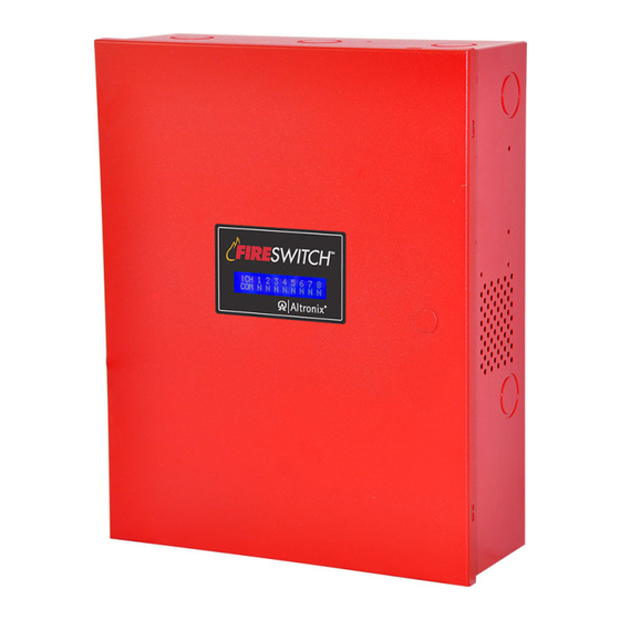
Overview: The Altronix FireSwitch108 is a cost effective managed NAC Power Extender. It interfaces with 12 or 24VDC Fire Alarm Control Panels (FACP) to provide Notification Appliance Circuit expansion support, for additional horns/strobes to allow ADA compliancy. It also provides auxiliary power to support system accessories. It delivers electronically regu- lated and filtered 24VDC power to Class B or Class A NAC loop circuits. -
Page 3: Power Supply Specifications
Use two (2) 12VDC/12AH or two (2) 12VDC/7AH or two (2) 12VDC/40AH Battery batteries connected in series. Stand-by/Alarm Current 180mA/200mA Consumption EOL Resistor (end of line) 10K (10,000 ohm), Altronix Model # AL-EOL10. (EOL10K-C for Canadian applications) Ground fault maximum 1000 ohm. test impedance Maximum Loop 1 ohm. - Page 4 Power Limited Outputs - Regulated Power Limited 2.5 amp per output in alarm (Supervised) When programmed for AUX - Special Application only Battery 2 Battery 1 Battery connections are (non-power limited): Use two (2) 12V battery hook-up in series - 4 - FireSwitch108...
- Page 5 (form “C” contact 1 amp / 28VDC 0.35 Power Factor) (Fig. 2, pg. 4). Designed to be connected to + INP1 --- or + INP2 --- of Altronix FireSwitch models only. Maximum of four (4) units can be interconnected, the distance between the units should not exceed + SYNC --- 20 ft., wiring to be in conduit, 20 AWG wire minimum.
-
Page 6: Led Diagnostics
LED Diagnostics: Power Supply Board Red (DC) Green (AC) Power Supply Status Normal operating condition. Loss of AC, Stand-by batteries supplying power. No DC output. Loss of AC. Discharged or no stand-by battery. No DC output. - 6 - FireSwitch108... -
Page 7: Wiring Diagram
Common Trouble Sync Power Limited Regulated NAC Outputs Power Limited Aux. Output Regulated 24VDC @ 1 amp ALL POWER LIMITED Power Limited WIRING IS TO BE ROUTED (0.45 for Canadian UNDER THE CHASSIS applications) (BETWEEN CHASSIS AND BACKBOX) FireSwitch108 - 7 -... -
Page 8: Hookup Diagram
Class A output (Combines two (2) outputs, ex. 1-2, 3-4, 5-6, 7-8). Class B output. Aux. output with battery backup. Aux. output without battery backup. Depress the joystick one time from Stand-by screen. Use [UP/DOWN] to select Function, Use [Left/Right] to select channel. - 8 - FireSwitch108... -
Page 9: Protocol Selection
Use [UP/DOWN] to select Protocol, Use [Left/Right] to select outputs. Use [Right] to copy setting to next output. Class A outputs are paired. If output is set for Ax or Bx - Protocol settings are not available. FireSwitch108 - 9 -... - Page 10 Version 4 (TCP/IPv4) or Internet Protocol Version 6 (TCP/IPv6), and then click Properties. d. To specify IPv4 IP address settings, click Obtain an IP address automatically, and then click OK. e. To specify IPv6 IP address settings, click Obtain an IPv6 address automatically, and then click OK. - 10 - FireSwitch108...
-
Page 11: Battery Calculation Worksheet
[+ BAT -] to insure there is no break in the battery connection wires. Note: Expected battery life is 5 years, however it is recommended changing batteries in 4 years or less if needed. FireSwitch108 - 11 -... -
Page 12: General Information
FireSwitch Applications: 1. General Information: Altronix FireSwitch units are very versatile devices. They can be used with or without specific synchronization modules provided by some manufacturers. Multiple units can be synchronized by using either the built-in sync mode or a external synchronization module. Please note, that only notification appliances with synchronization capabilities can be synchronized. - Page 13 FireSwitch is designed to follow (replicate) the coded sequence, generated by a manufacturer’s sync module. Up to eleven (11) FireSwitch108 units can be synchronized when interconnected with a host FACP. Connect the output of the FACP module to Input 1 and Input 2 Terminate the input circuit with the EOL (FACP), connecting it to terminals marked [RET+ and RET-], or continue the input circuit, connecting to terminals marked [RET+ and RET-] to [INP+ and INP-] of the next unit, when multiple units need to be triggered.
- Page 14 FireSwitch For continuous loop circuit use 10K EOL, (Altronix Model # AL-EOL10). When connecting, keep wires on different sides of the screw terminals in order to maintain loop integrity supervision. DO NOT LOOP CONTINUOUS WIRE AROUND THE SCREW.
- Page 15 Programmed for Following INP2 (2c) A total of four (4) FireSwitch units can be inter-connected INP2 RET2 For this application set Dip Switches for INP2 to “ON” position on all units, except the one triggered from FACP FireSwitch108 - 15 -...
- Page 16 SW3 to the OFF position. For INP2 to the sync output of FireSwitch unit for synchronization purposes set SW2 to the ON position and SW4 to the OFF position. INP1 - Dry NC ----------- ----------- INP2 - Dry NC ----------- ----------- INP1 - Sync ----------- ----------- INP2 - Sync ----------- ----------- - 16 - FireSwitch108...
-
Page 17: Appendix A - Ul/Cul Listed Compatible Devices For Synchronization
SL-24W - UL/cUL SSC8-177W - UL SSS8-75110W - UL SH-1224WP-R - UL/cUL SH24C-177R - UL/cUL SSR2-3075110R - UL SH-1224WP-W - UL/cUL SH24C-177W - UL/cUL SSR2-3075110W - UL SSC2-3075110R - UL SSS2-1530R - UL SSR2-177R - UL FireSwitch108 - 17 -... -
Page 18: Appendix B - Ul Listed Compatible Devices
B112LP Base 0.12 B114LP Base B404B Base DH100ACDC Photoelectric 0.15 0.70 DH100ACDCLP Photoelectric 0.15 0.70 DH100ACDCLPW Photoelectric 0.15 0.70 DH400ACDCI Ionization Duct DH400ACDCP Photoelectric Duct 1112/24/D Ionization 0.05 1424 Ionization 0.10 1451 (w/B402B Base) Ionization 0.10 - 18 - FireSwitch108... - Page 19 B.2 Relays Table B-3 below lists relays compatible with FireSwitch AUX output. Manufacturer Model Current (mA) Manufacturer Model Current (mA) PR-1 R-20T PR-2 R-24T PR-3 R-10E System Sensor System Sensor EOLR-1 R-14E R-10T R-20E R-14T R-24E FireSwitch108 - 19 -...
-
Page 20: Enclosure Dimensions
1.500" 4.615" 4.615" 1.500" Altronix is not responsible for any typographical errors. 140 58th Street, Brooklyn, New York 11220 USA, 718-567-8181, fax: 718-567-9056 web site: www.altronix.com, e-mail: info@altronix.com, Lifetime Warranty, Made in U.S.A. IIFireSwitch108 G08M MEMBER - 20 - FireSwitch108...
Need help?
Do you have a question about the FireSwitch108 and is the answer not in the manual?
Questions and answers