Altronix AL1002ULADA Installation Manual
Nac power extender, rack mountable nac power extender
Hide thumbs
Also See for AL1002ULADA:
- Installation manual (13 pages) ,
- Application manual (9 pages) ,
- Installation manual (17 pages)

Related Manuals for Altronix AL1002ULADA


Summary of Contents for Altronix AL1002ULADA
- Page 1 AL1002ULADA NAC Power Extender R1002ULADA Rack Mountable NAC Power Extender Installation Guide (see Application Guide for additional information) Altronix Corp. 140 58th St. Brooklyn, NY More than just power. Rev. 062320...
-
Page 2: Specifications
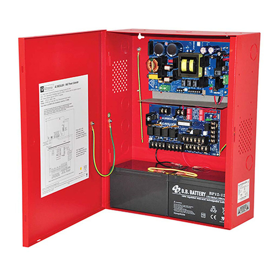
Overview: Altronix AL1002ULADA (wall mount) and R1002ULADA (rack mount) are extremely cost-effective 10A NAC power extenders with built-in battery charging. It may be connected to any 12 or 24 volt Fire Alarm Control Panel (FACP). Primary applications include Notification Appliance Circuit (NAC such as strobes and horns) expansion support to meet ADA requirements. -
Page 3: Power Supply Specifications
Use two (2) 12VDC / 7AH, two (2) 12VDC / 12AH or two (2) 12VDC / 36AH Battery batteries connected in series. Stand-by/Alarm 130mA/300mA Current Consumption: EOL Resistor (end of line): 2.2K (2200 Ohm), Altronix Model # AL-EOL22 (included). Ground fault maximum 1000 Ohm. test impedance: Stand-by Specifications: Stand-by Time Total... - Page 4 Secure enclosure to earth ground (Fig. 5, pg. 5). Small terminal block wire gauges range from 16 AWG to 24 AWG, all others range from 14 AWG to 24 AWG. Z Bracket Installation for R1002ULADA: Altronix R1002ULADA enclosure includes Z Bracket, a convenient and reliable wire management accessory. Hardware (included): Ten (10) bolts and eight (8) lock nuts.
-
Page 5: Installation Instructions
If additional battery enclosure is required, it must be UL Listed for the application and mounted within 5’ of the AL1002ULADA enclosure in the same room; minimum 12 AWG wire in appropriate conduit is required for connection. When using conduit, make sure it is installed in a matter where it can not turn. - Page 6 (strobes) to be silenced/ deactivated at Cooper Wheelock. the same time. *Note: The AL1002ULADA/R1002ULADA will only synchronize horns, horn/strobes and strobes that contain synchronization capability. The same synchronization mode must be selected for all outputs Amount of Notification Appliances per NAC:...
- Page 7 For loads connected to “AUX” please refer to battery “Stand-by Specifications”, pg. 3 for ratings. When loads are connected to “AUX” output during alarm condition, the remaining outputs may not exceed 10A total alarm current (example: AUX = 1A, outputs up to 10A). AL1002ULADA / R1002ULADA - 7 -...
-
Page 8: Led Diagnostics
To reset the memory depress the reset button (Fig. 8c, pg. 11). The LED(s) will extinguish. Note: If indicating circuits have been restored, memory reset is not required for normal operation of the unit. - 8 - AL1002ULADA / R1002ULADA... - Page 9 NEC Power-Limited Wiring Requirements for AL1002ULADA Models: Power-limited and non power-limited circuit wiring must remain separated in the cabinet. All power-limited circuit wiring must remain at least 0.25” away from any non power-limited circuit wiring. Furthermore, all power-limited circuit wiring and non power-limited circuit wiring must enter and exit the cabinet through differ- ent conduits.
- Page 10 Non Power- Non Power- Power-Limited Limited Limited Non-Supervised Class E Power-Limited Supervised Power-Limited Outputs Power-Limited 2.5A per output in alarm Supervised Power-Limited Non-Supervised Power-Limited Class E NO C "FAULT" NC Non-Supervised Class E Power-Limited - 10 - AL1002ULADA / R1002ULADA...
- Page 11 BAT FAIL AC FAIL AL1002ULADA / R1002ULADA - 11 -...
-
Page 12: Maintenance
Input fuse rating is 6.3A@ 250V, Output fuse rating is 15A @ 32V. Note: Maximum charging current is 1.5A. Note: Expected battery life is 5 years; however, it is recommended changing batteries in 4 years or less if needed. - 12 - AL1002ULADA / R1002ULADA... -
Page 13: Battery Calculation Worksheet
(30% extra insurance to meet desired performance) Total ampere - hours required Units are capable of recharging 36AH battery max. If total ampere - hour required exceeds 36AH, decrease AUX current to provide enough stand-by time for the application. AL1002ULADA / R1002ULADA - 13 -... -
Page 14: Appendix A: Compatible Ul/Cul Listed Devices For Synchronization
Appendix A: Compatible UL/cUL Listed Devices for Synchronization –––––––––––––––––––––––––––––––––––––––––––––––––––––––––––––––––––––––––––––––––––––––––– A-1 Strobes, Horns, and Horn/Strobes Table A-1 below lists Strobes, Horns, and Horn/Strobes compatible with AL1002ULADA/R1002ULADA NAC outputs. System Sensor: CHSR - UL P4R-SP - UL PC4RH-P - UL SPSCW - UL... - Page 15 Appendix A (cont’d): Compatible UL/cUL Listed Devices for Synchronization –––––––––––––––––––––––––––––––––––––––––––––––––––––––––––––––––––––––––––––––––––––––––– A-1 Strobes, Horns, and Horn/Strobes (cont’d) Table A-1 below lists Strobes, Horns, and Horn/Strobes compatible with AL1002ULADA/R1002ULADA NAC outputs. Gentex: GCS24CR - UL GCCB24PCR / W - UL GEC24-15/75WR - UL...
- Page 16 Appendix A (cont’d): Compatible UL/cUL Listed Devices for Synchronization –––––––––––––––––––––––––––––––––––––––––––––––––––––––––––––––––––––––––––––––––––––––––– A-1 Strobes, Horns, and Horn/Strobes (cont’d) Table A-1 below lists Strobes, Horns, and Horn/Strobes compatible with AL1002ULADA/R1002ULADA NAC outputs. Cooper/Wheelock: 50-241575W-FR - UL/cUL E70-24MCW-FN - UL/cUL ET90-24MCCH-FN - UL/cUL LSTW-A* - UL/cUL...
-
Page 17: Appendix B - Ul Listed Compatible Devices
Appendix B - UL Listed Compatible Devices ––––––––––––––––––––––––––––––––––––––––––––––––––––––––––––––––––––––––––––––––––––––– B-1 Relays Table B-2 below lists relays compatible with AL1002ULADA/R1002ULADA AUX output and Outputs 1-8 when programmed as AUX. Manufacturer Model Current (mA) Manufacturer Model Current (mA) PR-1 R-20T PR-2 R-24T PR-3... - Page 18 Notes: - 18 - AL1002ULADA / R1002ULADA...
- Page 19 AL1002ULADA Enclosure Dimensions: 15.5” x 12” x 4.5” (393.7mm x 304.8mm x 114.3mm) 1.5” 1.5” 4.615” (117.2mm) 4.615” (117.2mm) (38.1mm) (38.1mm) 1.75” (44.5mm) 1.25” 1.25” 4.5” (114.3mm) 4.5” (114.3mm) 12.23” (310.6mm) (31.8mm) (31.8mm) 1.1” (27.9mm) 1.1” (27.9mm) 1.375” 1.5” 1.5”...
- Page 20 3.25” 82.3mm Altronix is not responsible for any typographical errors. 140 58th Street, Brooklyn, New York 11220 USA | phone: 718-567-8181 | fax: 718-567-9056 website: www.altronix.com | e-mail: info@altronix.com | Lifetime Warranty | Made in U.S.A. MEMBER IIAL1002ULADA/R1002ULADA B16U - 20 -...
Need help?
Do you have a question about the AL1002ULADA and is the answer not in the manual?
Questions and answers