Advertisement
Quick Links
Advertisement

Related Manuals for Altronix AL800ULADA


Summary of Contents for Altronix AL800ULADA
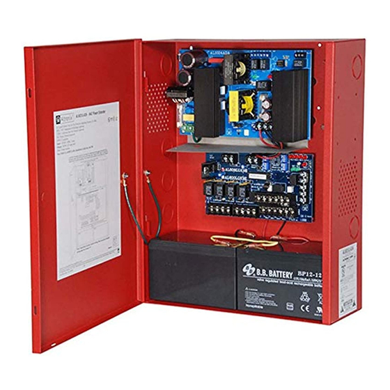
- Page 1 AL800ULADA NAC Power Extender Installation Guide Rev. 122000...
- Page 2 The AL800ULADA in non-alarm condition provides independent loop supervision for Class A and/or Class B FACP NAC circuits. In the event of a loop trouble the FACP will be notified via the AL800ULADA’s steered input (input 1 or input 2). In addition, there are common trouble output terminals (NC, C, NO) which are used to indicate general loop/system trouble.
- Page 3 The AL800ULADA should be installed in accordance with article 760 of The National Electrical Code as well as NFPA 72 and all applicable Local Codes. 1. Mount the AL800ULADA in a desired location. It is recommended to first review the following tables for screw XFMR terminals, switch selection and LED status indications.
- Page 4 Mode 4 Will accept a steady or pulsing input. (Amseco). Note: The AL800ULADA will only synchronize strobes that contain synchronization capability. Contact signal manufacturer for more detailed info. The same synchronization mode must be selected for all outputs. When using 2-wire horn/strobes, horns will be silenced.
- Page 5 ** Indicates trouble condition memory. When a trouble condition restores, the units red output LED, (OUT1- OUT4) will blink with a shorter and distinctly different duration. The green input LED(s) will be off (normal condition). To reset the memory remove and restore AC and battery power to the unit. The LED(s) will extiguish. Note: If indicating circuits have been restored, memory reset is not required for normal operation of the unit.
- Page 6 Power Supply Board Terminal Function/Description Legend AC/AC Low voltage AC input. -- DC + 12VDC or 24VDC @ 8 amp continuous non-power limited output. AC FAIL Form “C” dry contacts used to signal the loss of AC, with AC present terminals N.O. and C are C, N.C., N.O.
- Page 7 INPUT SELECT TEMPORAL OUT1 OUT2 OUT3 OUT4 STROBE SYNC IN > OUT SYNC INP1 INP2 OUT2 OUT4 FAULT INPUT SELECT NO "REMOTE " C TEMPORAL RESET STROBE SYNC IN > OUT SYNC Typical Application Diagrams: AL800LGK Class B hookup: Fig. 2 •...
- Page 8 Optional Hookup Diagram: Ground Fault Ground Fault Fig. 4 Detection Disabled Detection (Factory Set) Fig. 4C Fig. 4A Fig. 4B Plastic Plastic Washer Washer Power Supply Power Supply Board Board Stand-Off Stand-Off Fire Alarm OPEN = 24V SW1 CLOSED = 12V XFMR XFMR Control...
- Page 9 Note: When using this configuration you must enable the Input to Output Follower Mode (Dip Switch 1 ON) and disable the Strobe Sync Mode (Dip Switch 2 OFF). 2.2K Sync Module AL800ULADA 2.2K FACP ADA Compliant (Fire Alarm NAC Power Control Panel) 2.2K...
- Page 10 Typical Application Diagram for Connecting Horn/Strobes With Independent Control of Horns and Strobes: --- AUX + --- DC + OUT1 OUT3 INPUT SELECT TEMPORAL OUT1 OUT2 OUT3 OUT4 STROBE SYNC IN > OUT SYNC INP1 INP2 OUT2 OUT4 FAULT INPUT SELECT NO "REMOTE "...
- Page 11 Enclosure Dimensions: 15.5”H x 12”W x 4.5”D 12" 2.25" 3.68" 4.56" 1.22" 4.5" 1.22" 1.22" .875" 1.3" 9.97" 1" 1" 2" 2" 8" 13.25" 13.53" 3.25" 2.2" 1.25" 1" 15.5" 1.22" 2.25" 3.68" 4.56" - 11 -...
- Page 12 Notes: Altronix is not responsible for any typographical errors. Altronix Corp. 140 58th Street, Brooklyn, New York 11220 USA, 718-567-8181, fax: 718-567-9056 web site: www.altronix.com, e-mail: info@altronix.com, Lifetime Warranty, Made in U.S.A. IIAL800ULADA G29E MEMBER - 12 -...
Need help?
Do you have a question about the AL800ULADA and is the answer not in the manual?
Questions and answers