
Related Manuals for Go Power GP-SW3000


Summary of Contents for Go Power GP-SW3000
- Page 1 Go Power! Manual GP-SW3000 Inverter GP-SW2000 Inverter GP-SW1000 Inverter GP-SW600 Inverter...
-
Page 3: Table Of Contents
Warranty Return Procedure ................. 25 Additional Information ..................26 Out of Warranty Items ..................26 Configuring your GP-SW3000, GP-SW2000, GP-SW1000, and GP-SW600....................27 10.1 Configuring the Dip Switches GP-SW3000, GP-SW2000, and GP-SW1000 . 27 10.2 Other Dip Switches (Professional Installer Only) ..........27... -
Page 4: Introduction
Owner’s Manual 1. Introduction The Go Power! Sine Wave series models are used in a wide range of applications including remote homes, RVs, sailboats, and powerboats. It will operate most televisions and VCRs, personal computers, small appliances, and tools such as drills, sanders, grinders, mixers and blenders. -
Page 5: Specifications
Go Power! GP-SW3000, GP-SW2000, GP-SW1000and GP-SW600 Owner’s Manual 2. Specifications 2.1 GP-SW3000 W Inverter GP-SW3000 Specification 12 V 24 V Continuous output power 3000 W Surge rating 6000 W Output waveform Sine Wave <3% THD Output Voltage ± 3% 115 VAC RMS Output Frequency ±... -
Page 6: Gp-Sw2000 W Inverter
Go Power! GP-SW3000, GP-SW2000, GP-SW1000and GP-SW600 Owner’s Manual 2.2 GP-SW2000 W Inverter GP-SW2000 Specification 12 V 24 V Continuous output power 2000 W Surge rating 4000 W Output waveform Sine Wave <3% THD Output Voltage ± 3% 115 VAC RMS Output Frequency ±... -
Page 7: Gp-Sw1000 W Inverter
Go Power! GP-SW3000, GP-SW2000, GP-SW1000and GP-SW600 Owner’s Manual 2.3 GP-SW1000 W Inverter GP-SW1000 Specification 12 V 24 V Continuous Output Power 1000 W Surge Rating 2000 W Output Waveform Sine Wave <3% THD Output Voltage ± 3% 115 VAC RMS Output Frequency ±... -
Page 8: Gp-Sw600 W Inverter
Go Power! GP-SW3000, GP-SW2000, GP-SW1000and GP-SW600 Owner’s Manual 2.4 GP-SW600 W Inverter GP-SW600 Specification 12 V 24 V Continuous Output Power 600 W Surge Rating 860 W Output Waveform Sine Wave <3% THD Output Voltage ± 3% 115 VAC RMS Output Frequency ±... -
Page 9: Inverter Drawings
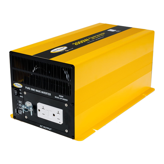
Go Power! GP-SW3000, GP-SW2000, GP-SW1000and GP-SW600 Owner’s Manual 3. Inverter drawings 3.1 GP-SW3000 and GP-SW2000 3.1.1 Front view (GP-SW3000 and GP-SW2000) i) AC outlets a) Ventilation b) On / Off switch c) Input level d) Load level e) Status f) Frequency... - Page 10 Go Power! GP-SW3000, GP-SW2000, GP-SW1000and GP-SW600 Owner’s Manual 3.1.2 Rear view (GP-SW3000 and GP-SW2000) a) Ventilation b) Remote port c) Chassis ground d) Battery terminals Operation of the inverter without a proper ground connection may result in an electrical safety hazard.
-
Page 11: Gp-Sw1000
Go Power! GP-SW3000, GP-SW2000, GP-SW1000and GP-SW600 Owner’s Manual 3.2 GP-SW1000 3.2.1 Front view (GP-SW1000) a) On / Off switch b) AC outlets c) Input level d) Load level e) Status f) Ventilation ports g) Frequency h) Power save ON / OFF switch: Power ON/OFF switch, leave in the OFF position during installation. - Page 12 Go Power! GP-SW3000, GP-SW2000, GP-SW1000and GP-SW600 Owner’s Manual 3.2.2 Rear view (GP-SW1000) c) Ventilation port b) Remote port a) Chassis ground d) Battery terminals Operation of the inverter without a proper ground connection may result in an electrical safety hazard.
-
Page 13: Gp-Sw600
Go Power! GP-SW3000, GP-SW2000, GP-SW1000and GP-SW600 Owner’s Manual 3.3 GP-SW600 3.3.1 Front view (GP-SW600) a) On / Off switch b) AC outlets c) Input level d) Load level e) Fault f) Frequency g) Ventilation ports ON / OFF switch: Power ON/OFF switch, leave in the OFF position during installation... - Page 14 Go Power! GP-SW3000, GP-SW2000, GP-SW1000and GP-SW600 Owner’s Manual 3.3.2 Rear view (GP-SW600) b) Ventilation port a) Chassis ground c) Battery terminals Operation of the inverter without a proper ground connection may result in an electrical safety hazard. Chassis Ground: Ground to vehicle chassis using # 8 AWG wire.
-
Page 15: Installation
For hook-up, please follow these guidelines: 1. Unpack and inspect your Go Power! Inverter, then check to see that the power switch is in the OFF position. Set up your power output according to Section 10, Configuring your Sine Wave. -
Page 16: Hard Wire
GP-SW600-24V: Please use 8 ft or less of #8 Cable with a 70 Amp fuse. A GP-DC Kit 2 suitable for both 12 and 24 V applications is available from Go Power Inc. (please use the included GP-SW600 crimp lugs for this application). -
Page 17: Grounding
GP-SW1000-24V: Please use 10 ft or less of #6 Cable with a 70 Amp fuse. A GP-DC Kit 2 suitable for both 12 and 24 V applications is available from Go Power Inc. GP-SW2000-12V: Please use 10 ft or less of 2/0 Cable with a 300 Amp fuse. -
Page 18: Operation
2.5 W (GP-SW600), 14.4 W (GP- SW1000, GP-SW2000 and GP-SW3000) from the battery. When in Power Save mode the GP-SW1000, GP-SW2000 and GP-SW3000 will draw approximately 3.0 W from the battery. -
Page 19: Over Temp Indicator (Otp)
5.8 Over Temp Indicator (OTP) During over temp, the fault light (GP-SW600) or status light (GP-SW1000, GP-SW2000 and GP-SW3000) will continually flash red twice every other second, five double beeps will sound and the AC output will disconnect. 5.9 Maximum Load / Overload Indicator (OLP) During maximum load, the GP-SW600, GP-SW1000 and GP-SW2000 Load Level LED will flash red twice per second and five single beeps will sound every eight seconds. -
Page 20: Remote
Owner’s Manual 5.12 Remote The GP-SW1000, GP-SW2000 and GP-SW3000 are available with an optional remote. The remote will turn the inverter on and off and indicate normal operation or any faults that have caused the inverter to shut down. The remote will show battery voltage and power consumption. -
Page 21: Operating Limits
Go Power! GP-SW3000, GP-SW2000, GP-SW1000and GP-SW600 Owner’s Manual 6. Operating limits 6.1 Input voltage: The power inverter will operate from input voltage ranging 10.5 to 15 V (12 V) or 21 to 30 V (24 V). If the voltage drops below 11 V (12 V) or 22 V (24 V), the Input Level LED will flash red twice per second and five single beeps will sound every eight seconds. -
Page 22: Troubleshooting
Go Power! GP-SW3000, GP-SW2000, GP-SW1000and GP-SW600 Owner’s Manual 7. Troubleshooting 7.1 Common problems Television interference: Operation of the power inverter can interfere with television reception on some channels. If this situation occurs, the following steps may help to alleviate the problem: •... -
Page 23: Maintenance
Go Power! GP-SW3000, GP-SW2000, GP-SW1000and GP-SW600 Owner’s Manual 8. Maintenance Very little maintenance is required to keep your inverter operating properly. You should clean the exterior of the unit periodically with a damp cloth to prevent accumulation of dust and dirt. At the same time, tighten the screws on the DC input terminals. -
Page 24: Warranty
(“Sale Date”), that the Go Power! Product provides coverage as follows: For the period ending 2 years from the Sale Date, Go Power! will, at Go Power!’s discretion, repair or replace the Product which fails to meet the Product Specifications due to a defect in materials or workmanship or apply credit towards the purchase of new Go Power! Product. -
Page 25: Warranty Return Procedure
Go Power! Product shall in no event exceed the purchase price of the Go Power! Product which gave rise to the claim. IN NO EVENT SHALL... -
Page 26: Additional Information
Go Power! GP-SW3000, GP-SW2000, GP-SW1000and GP-SW600 Owner’s Manual Additional Information Unless approved by Go Power! management, all product shipped collect to Go Power! will be refused. Test items or items that are not under warranty, or units that are not defective, will be charged a minimum bench charge of ($50.00 US) plus taxes and shipping. -
Page 27: Configuring Your Gp-Sw3000, Gp-Sw2000, Gp-Sw1000, And Gp-Sw600
The default voltage setting for the GP-SW600, GP-SW1000, GP-SW2000, and GP-SW3000 is 115 V AC, however all these inverters may be configured for other voltages by a professional installer via the two red dip switches located close to the AC connection inside each unit. - Page 28 © 2008 Carmanah Technologies Corporation www.carmanah.com Go Power! Building 4, 203 Harbour Road Victoria, British Columbia Canada V9A 3S2 Toll Free: 1.877.722.8877 | Fax: +1.250.380.0062 Email: info@carmanah.com Number: GP-SW600_SW3000_57150_Manual_vB 57150...
Need help?
Do you have a question about the GP-SW3000 and is the answer not in the manual?
Questions and answers