Table of Contents
Advertisement
Quick Links
Connection Diagrams
GP Inverter
GP Fuse
*Installation using two 12 volt batteries.
GP Fuse
GP Inverter
*Installation using two 6 volt batteries.
Go Power! Modified Sine Wave Inverter
Owner's Manual
12 V Batteries
6 V Batteries
Go P
Go Po o o o o w w w w w er! Man
Go P
er! Man
er! Man
Go P
Go P
er! Man
er! Manual
GP-1000 Inverter
Canadian Contact Information
Go Power!
A Division of Carmanah
Technologies Corporation
4, 203 Harbour Rd
Victoria, BC V9A 3S2
Tel: 800-667-6527
Fax: 250-380-0062
Email: info@gpelectric.com
ual
ual
ual
ual
Advertisement
Table of Contents

Related Manuals for Go Power GP-1000


Summary of Contents for Go Power GP-1000
- Page 1 Go Po o o o o w w w w w er! Man er! Man er! Man Go P Go P er! Man er! Manual GP-1000 Inverter 12 V Batteries GP Fuse *Installation using two 12 volt batteries. GP Fuse GP Inverter 6 V Batteries *Installation using two 6 volt batteries.
- Page 2 Go Power! Modified Sine Wave Inverter Go Power! Modified Sine Wave Inverter Owner’s Manual Owner’s Manual Maintenance Very little maintenance is required to keep your inverter operating properly . You should Table of Contents clean the exterior of the unit periodically with a dry cloth to prevent accumulation of dust and dirt.
-
Page 3: Specifications
95-105 VAC. meter. 2. Specifications Overload No output voltage, LED Turn off. Reduce load, turn indicator is orange. Model No. GP-1000 Continuous Output Power 1000 W Low DC input voltage No output voltage, LED Recharge battery, check Surge Rating 1300 W Inverter switched off. -
Page 4: Troubleshooting
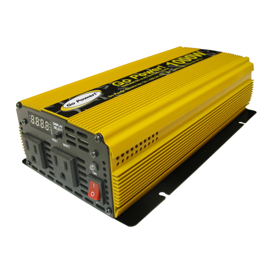
6.2 Overload The status LED will be orange and will come on when the power inverter has shut itself 3.1 Front view – GP-1000 down because its output circuit has been short circuited or drastically overloaded. Switch the ON/OFF switch to OFF , correct the fault condition, and then switch the ON/OFF switch c) Status light back to ON. -
Page 5: Operating Limits
Owner’s Manual 4.6 Grounding 3.1 Rear view – GP-1000 The power inverter has a lug on the rear panel: “Chassis Ground.” This is to connect the chassis of the power inverter to the ground. The ground terminals in the AC outlets on the... - Page 6 See “Grounding” for more information. • GP-1000 – 110 amp fuse 7. Set the power switch to the ON position. Check that the power LED is ON, and if not, check your battery bank and the connections to the inverter .
Need help?
Do you have a question about the GP-1000 and is the answer not in the manual?
Questions and answers