Table of Contents
Advertisement
Quick Links
See also:
User Manual
Advertisement
Table of Contents

Related Manuals for Go Power GP-1750HD GP


Summary of Contents for Go Power GP-1750HD GP
- Page 1 Go Power! Manual GP-1750HD GP Inverter GP-2500 GP Inverter Go Power! Electric Inc. PO Box 6033 Victoria, BC V8P 5L4 Tel: 866-247-6527 Fax: 866-607-6527 Email: info@gpelectric.com...
-
Page 2: Table Of Contents
Go Power! Modified Sine Wave Inverter Owner’s Manual Table of Contents INTRODUCTION....................3 SPECIFICATIONS ................... 3 FEATURES...................... 4 INSTALLATION....................7 OPERATION....................10 OPERATING LIMITS ..................11 TROUBLESHOOTING .................. 12 MAINTENANCE..................... 13 WARRANTY ....................13 RV SUPPLEMENT..................14 Go Power! Electric Inc. -
Page 3: Introduction
Owner’s Manual 1. Introduction The Go Power! Inverter series provides mobile power for people on the go. Run standard AC appliances wherever you travel. Silent, lightweight and simple to use, Go Power! Inverters can be used in a wide range of applications including remote homes, RVs, boats and long haul trucks. -
Page 4: Features
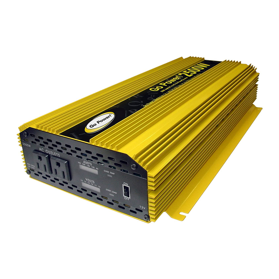
Go Power! Modified Sine Wave Inverter Owner’s Manual 3. Features 3.1 Front view – GP2500 b. AC outlets a. Bar graph meters g. Over temp indicator c. Voltage graph d. Overload indicator e. On/Off switch f. Remote On / Off a) Bar graph meters: Display battery voltage and current. - Page 5 Go Power! Modified Sine Wave Inverter Owner’s Manual 3.2 Front view – GP1750HD b. Over Temp. indicator Bar graph meters f. Remote On/Off d. Overload indicator c. AC outlets e. On/Off connector a) Bar graph meters: Display battery voltage and current. Current should be in the green zone for continuous operation.
- Page 6 Go Power! Modified Sine Wave Inverter Owner’s Manual 3.3 Rear view – GP 2500 b. Battery terminals a. Ventilation port Warning! a) Ventilation port: Do not obstruct, allow at least 1 inch for air flow. Operation of the inverter without a...
-
Page 7: Installation
Go Power! Modified Sine Wave Inverter Owner’s Manual 3.4 Rear view – GP1750HD a. Ventilation window b. Battery terminals c. Chassis ground a) Ventilation port: Do not obstruct, allow at least 1 inch for air flow. b) Battery terminals: Connect to 12 V battery or other 12 V power source. Note that "+" is positive, "-" is negative. - Page 8 4.2 Hook-up and testing To hook-up the inverter please follow these guidelines: 1. Unpack and inspect your Go Power! Inverter, check to see that the power switch is Caution! in the OFF position. We recommend using DC Install Kits whenever installing a GP A reverse polarity Inverter.
-
Page 9: Inverter Fuse
Go Power! Modified Sine Wave Inverter Owner’s Manual 4.3 DC Kits Go Power! DC Installation Kits include everything you will need to properly connect your Go Power! Inverter to the batteries. • GP-2500, GP-SW2000-12 – Use GP Install Kit 4 •... -
Page 10: Operation
Go Power! Modified Sine Wave Inverter Owner’s Manual *Installation using two 12 volt batteries 12 V GP Inverter Fuse 12 V * Installation using two 12 volt batteries. Fuse GP Inverter * Installation using two 6 V batteries. 5. Operation To operate the power inverter, turn it on using the ON/OFF switch on the front panel. -
Page 11: Operating Limits
Go Power! Modified Sine Wave Inverter Owner’s Manual 5.3 Battery voltage indicator The battery voltage bar graph indicates the voltage at the input terminals of the power inverter. At low input current, this voltage is very close to the battery voltage. At high input current, this voltage will be lower than the battery voltage. -
Page 12: Troubleshooting
Go Power! Modified Sine Wave Inverter Owner’s Manual 6.2 Input voltage The power inverter will operate from input voltage ranging 10 V – 15 V. If the voltage drops below 10.7 V, an audible low battery warning will sound and the voltage indicator will be in the lower red zone. -
Page 13: Maintenance
Go Power! Modified Sine Wave Inverter Owner’s Manual No output voltage, no voltage Inverter switched off. Turn inverter on. Check indication. No power to wiring to inverter. inverter. Internal fuse open. Have qualified service technician check and replace. Reverse DC polarity. -
Page 14: Rv Supplement
Go Power! Modified Sine Wave Inverter Owner’s Manual 10. RV Supplement 10.1 Installing the GP 2500, GP 1750HD, and without an automatic transfer switch • Plug main power cord into inverter (a 15 amp adapter may be required). • Battery inter-connects should be a minimum of 4 gauge.
Need help?
Do you have a question about the GP-1750HD GP and is the answer not in the manual?
Questions and answers