Table of Contents
Advertisement
Quick Links
Advertisement
Table of Contents

Related Manuals for Go Power GP-ISW-200


Summary of Contents for Go Power GP-ISW-200
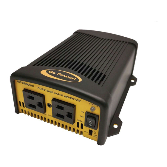
- Page 1 PURE SINE WAVE INVERTER GP-ISW-200/400 User Manual © 2018 Go Power! ® Worldwide Technical Support and Product Information gpelectric.com Go Power! Headquarters 201-710 Redbrick St, Victoria, BC Canada V8T 5J3 Tel: 1.866.247.6527 82654_MAN_ISW200-400_RevA...
- Page 2 Congratulations on purchasing your Go Power! GP-ISW Inverter. The unit is a highly reliable DC- AC inverter system, designed with advanced power electronic and microprocessor technology offering the following features; • Pure Sine wave output (THD <5%). • Intelligent power management software.
-
Page 3: Table Of Contents
1. CONTENTS GENERAL INFORMATION ....................4 CAUTIONS / WARNINGS .................4 DISCLAIMERS....................10 GP-ISW KIT PARTS..................11 2.3.1 PARTS CHECKLIST ................. 11 UNIT DIMENSIONS ..................12 VOLTAGE AND TEMPERATURE PERFORMANCE ........13 INSTALLATION .........................15 TYPICAL SYSTEM OVERVIEW ..............15 MOUNTING REQUIREMENTS ..............16 DC WIRING ....................18 3.3.1 DC WIRING SIZING .................19 3.3.2... -
Page 4: General Information
2.1 CAUTIONS / WARNINGS This document contains important safety instructions for the products produced by Go Power. Read all instructions and cautionary markings on the product and on any accessories or additional equipment included in the installation. Failure to follow these instructions could result in severe shock or possible electrocution. - Page 5 CAUTION! Equipment Damage Only use components or accessories recommended or sold by Go Power! or its authorized agents. Do not attempt to install this equipment if it appears to IMPORTANT be damaged in any way. See the Warranty section for instructions on returning the equipment.
- Page 6 GENERAL INFORMATION Personal Safety Use safe lifting techniques when lifting this equipment as recommended by the Occupational Safety and Health Association (OSHA) or other local codes. Use standard safety equipment when working on this equipment, such as safety glasses, ear protection, steel- toed safety boots, safety hard hats, etc.
- Page 7 WARNING! installation instructions unless qualified to do so, or have Lethal Voltage been instructed to do so by Go Power! Technical Support personnel. To avoid electric shock, disconnect the DC input and AC input of the inverter at least 5 minutes before performing any installation or maintenance.
- Page 8 GENERAL INFORMATION Battery Safety Ensure the cables (conductors) are properly sized. Ensure clearance requirements are strictly enforced around the batteries. Ensure the area around the batteries is well ventilated and clean of debris. Never smoke, or allow a spark or flame near the batteries. WARNING! Always use insulated tools.
- Page 9 GENERAL INFORMATION Use the battery types recommended by Go Power. Follow the battery manufacturer’s recommendations for installation and maintenance. Insulate batteries as appropriate against freezing temperatures. A discharged battery will freeze more easily than a charged one. If a remote or automatic generator control system is used,...
-
Page 10: Disclaimers
We have made every reasonable effort to ensure the accuracy of the instructions in this manual, but Go Power does not guarantee that the information is error free, nor do we make any other representation, warranty or guarantee that the information is accurate, correct, reliable or current. -
Page 11: Gp-Isw Kit Parts
2.3 GP-ISW KIT PARTS Please unpack and make sure all parts shown in the list below are included in the kit. If any parts are missing please contact Go Power customer service team at customersupport@ gpelectric.com or 1.866.247.6527. 2.3.1 PARTS CHECKLIST... -
Page 12: Unit Dimensions
GENERAL INFORMATION 2.4 UNIT DIMENSIONS Model A (mm) B (mm) C (mm) D (mm) E (mm) F (mm) GP-ISW200 35.7 GP-ISW400 35.7 GP-ISW700 GP-ISW1000 GP-ISW1500 GP-ISW2000 GP-ISW3000 GP-ISW4000 [page 12] | gpelectric.com... -
Page 13: Voltage And Temperature Performance
150 mm X 68mm X187 mm Weight 1.6kg Others Remote Control CR-8 (optional) GP-SWR-A Cooling Temperature & Load Controlled cooling Fan Table 1. GP-ISW-200 Specification Note: This test condition is normal DC input and temperature 25˚C gpelectric.com | [page 13]... - Page 14 GENERAL INFORMATION GP-ISW-400 Specification Specification Model No. 2-3-3. GP400 Specification Electrical Item GP-ISW-400-12 GP-ISW-400-24 Specification Model No. Voltage 12VDC 24VDC Electrical Item GP400-112 GP400-124 GP400-148 Voltage Range 10.5~16.0VDC 2 1.0~32.0VDC No Load Current < 1A @12VDC < 0.5A @24VDC Voltage 12VDC 24VDC 48VDC...
-
Page 15: Installation
RV application. The diagrams show where the remote and Inverter are installed and how the mobile power system can be integrated with a Go Power! RV Solar Kit (sold separately by Go Power, please contact an authorized dealer directly). -
Page 16: Mounting Requirements
INSTALLATION 3.2 MOUNTING REQUIREMENTS 1. TEMPERATURE Make sure the GP-ISW is installed in a location where the normal air temperature is between -20°C and 40°C. The cooler the better within this range. 2. MOISTURE Do not allow water or other fluids to come into contact with the GP-ISW. Do not expose to rain, snow or water. - Page 17 INSTALLATION HORIZONTAL WALL MOUNT, BASE DOWN HORIZONTAL WALL MOUNT, BASE DOWN HORIZONTAL MOUNT, BASE DOWN HORIZONTAL MOUNT, BASE UP VERTICAL MOUNT, DO NOT MOUNT THE GP-ISW IN THIS CONFIGURATION *GP-ISW model may not be exactly as shown gpelectric.com | [page 17]...
-
Page 18: Dc Wiring
INSTALLATION 3.3 DC WIRING Solar Panel ISW Remote Control (Optional) GP-ISW Loads DC Panel Battery Disconnect Switch (not required if circuit breaker is used) Fuse or Circuit Breaker Earth Ground (RV Ground) Fuse Battery Bank To Battery Bank To Battery Bank The following points must be observed for the DC Wiring. -
Page 19: Dc Wiring Sizing
INSTALLATION 3.3.1 DC WIRING SIZING The distance between the battery bank and the GP-ISW should be as short as possible to achieve maximum efficiency and to reduce fire hazards. The size of the cable should be thick enough to limit the voltage drop to less than 2% when carrying the maximum input current to prevent frequent low-input voltage warnings and shutdown. -
Page 20: Dc Overcurrent Protection
3.3.3 PREPARING THE DC CABLES Go Power! supplies 2 ring lugs with the GP-ISW which can be used for the Inverter end of the DC Cables. Source the correct ring terminals for the batteries you are using. -
Page 21: Wiring The Inverter To The Batteries
INSTALLATION To help prevent seizing and corrosion around the terminals the use of an anti-seize lubricant is highly recommended. Apply the antioxidant grease or spray after all the connections are made and tightened. 3.3.5 WIRING THE INVERTER TO THE BATTERIES WARNING: Lethal currents will be present if the positive and negative cables attached to the battery bank touch each other. -
Page 22: Dc Grounding
INSTALLATION 3.3.6 DC GROUNDING To protect against electrical shock hazards the GP-ISW metal chassis must be connected to the DC grounding system. The DC grounding system is sometimes referred to as the earth ground or another designated ground. For example on an RV, the metal frame of the RV is designated as the negative DC ground / RV ground. -
Page 23: Ac Output Interface
3.4.2 GFCI (GROUND FAULT CIRCUIT INTERRUPTION) OUTLETS Compliance with UL standards requires that Go Power! test and recommend specific GFCIs for use on the AC output of the GP-ISW. GFCIs shall be installed in the AC output wiring system to protect all branch circuits. - Page 24 OPERATION 4. OPERATION GP-ISW-200 LED signal Status LED Signal Description Beep twice, LED shows red Power on orange green green R=red, O=orange, R=red Green LED lights in solid green Normal LED flashes green LED flashes green condition in...
-
Page 25: Operation
LED flashes red light every 0.1 Shut down over seconds, then inverter shut voltage down. OPERATION LED flashes red light slowly Fan alarm once and quickly twice every 1.6 seconds GP-ISW-400 LED signal Table 7. GP200 & GP350 LED status ... -
Page 26: Testing The Installation
OPERATION 4.2 TESTING THE INSTALLATION Apply battery power to the inverter by engaging the fuse or switching the breaker to the ON position. Disconnect all AC loads from the inverter. Press the ON/OFF button. The inverter will carry out self-diagnosis and the LED’s will also appear (various colors). -
Page 27: Inverter Status To Display Fault Condition
OPERATION Green 11.5 ~ 15.0V 23.0 ~ 30.0V Orange 15.0 ~ 15.5V 30.0 ~ 31.0V >15.5V >31.0V 4.4.2 INVERTER STATUS TO DISPLAY FAULT CONDITION LED status Status Recovery point Green Normal Over Current Protection / Over Load Protection (AC output short-circuit and over load) Under Voltage Protection 12.5V @ DC12V system... -
Page 28: Function Switch
OPERATION 4.5 FUNCTION SWITCH 4.5.1 OUTPUT VOLTAGE SELECTION (S1&S2) Output Voltage 100V 110V 115V 120V 4.5.2 OUTPUT FREQUENCY SELECTION (S3) Frequency 50Hz 60Hz 4.6 POWER SAVING SELECTION (S4) Saving Function Power Saving OFF Power Saving ON [page 28] | gpelectric.com... -
Page 29: Shutdown Conditions
OPERATION 4.7 SHUTDOWN CONDITIONS Over Voltage (DC) Under Voltage (DC) Under ISW200 Voltage /400 Alarm Shutdown Restart Shutdown Restart 14.5V± 10.5V ± 12.5V± 16V ± 0.3V 10V ± 0.3V 0.3V 0.3V 0.3V 33V ± 0.5V 29V ± 0.5V 21V± 0.5V 20V ±... -
Page 30: Warranty Return Procedure
Go Power! electronic products are non-repairable, Go Power! does not perform repairs on its products nor does it contract out those repairs to a third party. Go Power! does not supply schematics or replacement parts for any of its electronic products. -
Page 31: Product End Of Life & Recycling
If you have no local certified e-waste recycling centre, the GP-ISW can be disassembled manually and recycled responsibly. A Phillips screwdriver is required to disassemble the GP- ISW. Note: The GP-ISW should only be disassembled at the end of its service life. Go Power! provides no spare parts for the GP-ISW. - Page 32 © 2018 Go Power! ® Worldwide Technical Support and Product Information gpelectric.com Go Power! Headquarters 201-710 Redbrick St, Victoria, BC Canada V8T 5J3 Tel: 1.866.247.6527 82654_MAN_ISW200-400_RevA...
Need help?
Do you have a question about the GP-ISW-200 and is the answer not in the manual?
Questions and answers