Sign In
Upload
Download
Table of Contents
Contents
Add to my manuals
Delete from my manuals
Share
URL of this page:
HTML Link:
Bookmark this page
Add
Manual will be automatically added to "My Manuals"
Print this page
×
Bookmark added
×
Added to my manuals
Manuals
Brands
Go Power Manuals
Inverter
GP-225HD
User manual
Go Power GP-225HD User Manual
Modified sine wave inverter
Hide thumbs
1
Table Of Contents
2
3
4
5
6
7
8
9
10
11
12
13
14
15
16
17
18
19
20
21
22
23
24
25
26
27
28
29
30
31
32
page
of
32
Go
/
32
Contents
Table of Contents
Troubleshooting
Bookmarks
Table of Contents
Table of Contents
Contents
General Information
Cautions / Warnings
Disclaimers
Modified Hd Features
Specifications
Installation
Installation Precautions
Inverter Shutdown
Where to Install
Gp-225Hd: Installation and Testing
Gp-400/800/1000Hd: Installation and Testing
Battery Precautions
DC Wiring Sizing
DC Grounding
Operation
Operating Precautions
Connecting Ac Loads
Controls and Indicators
Optional On/Off Remote
Power Output
Input Voltage
Overtemp
Overload
Troubleshooting
Troubleshooting Guide
Maintenance
Servicing Precautions
Warranty Return Procedure
End of Life - Recycling
Advertisement
Quick Links
Download this manual
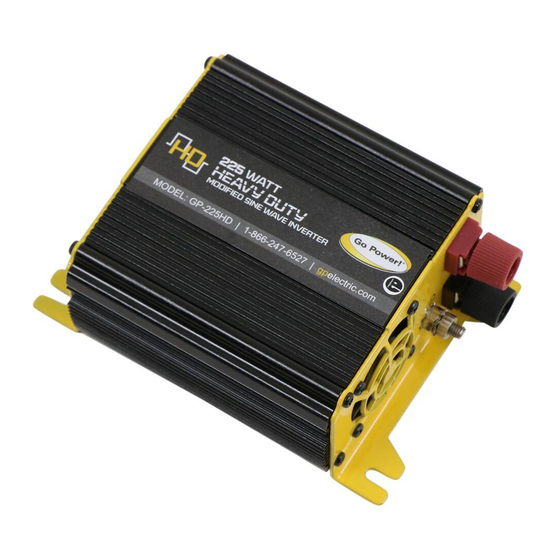
MODIFIED SINE WAVE
INVERTER
GP-225/400/800/1000HD
User Manual
© 2016 Go Power!
Worldwide Technical Support and Product Information
Go Power! Corporate Headquarters
250 Bay St, Victoria, BC Canada V9A 3K5
Tel: 1.866.247.6527
80690_MANUAL_GP-225-400-800-1000-HD_RevA
®
gpelectric.com
Table of
Contents
Previous
Page
Next
Page
1
2
3
4
5
Advertisement
Table of Contents
Need help?
Do you have a question about the GP-225HD and is the answer not in the manual?
Ask a question
Questions and answers
Related Manuals for Go Power GP-225HD
Inverter Go Power GP-1750HD GP Owner's Manual
Modified sine wave gp inverter (14 pages)
Inverter Go Power GP-12-300 Instruction Manual
Dc to ac (5 pages)
Inverter Go Power GP-3000HD Owner's Manual
Modified sine wave inverter (20 pages)
Inverter Go Power GP-SW2000 Manual
(16 pages)
Inverter Go Power GPSW-3000 Owner's Manual
Pure sine wave inverter (24 pages)
Inverter Go Power GPSW-300 Owner's Manual
Pure sine inverter (20 pages)
Inverter Go Power GP-SW150 Manual
(11 pages)
Inverter Go Power GPSW-600 Owner's Manual
Pure sine wave inverter (20 pages)
Inverter Go Power! GP-1000 Owner's Manual
(6 pages)
Inverter Go Power GP-FLEX-55 User Manual
(18 pages)
Inverter Go Power GP-PSK-80 User Manual
Portable solar kits (16 pages)
Inverter Go Power GP-PWM-30 User Manual
30 amp pwm solar controller (23 pages)
Inverter Go Power GP-ISW-700 User Manual
Pure sine wave inverter (42 pages)
Inverter Go Power GP-DURALITE-100 User Manual
Duralite 100-watt portable solar kit (20 pages)
Inverter Go Power GP-ISW-200 User Manual
Pure sine wave inverter (32 pages)
Inverter Go Power GP-PWM-30-SQ Owner's Manual
Solar charge controller 12volt 30amp (11 pages)
This manual is also suitable for:
Gp-400hd
Gp-800hd
Gp-1000hd
Table of Contents
Print
Rename the bookmark
Delete bookmark?
Delete from my manuals?
Login
Sign In
OR
Sign in with Facebook
Sign in with Google
Upload manual
Upload from disk
Upload from URL


Need help?
Do you have a question about the GP-225HD and is the answer not in the manual?
Questions and answers