
Subscribe to Our Youtube Channel
Related Manuals for Go Power GPSW-3000


Summary of Contents for Go Power GPSW-3000
- Page 1 Pure Sine Wave Inverter GPSW-1000 GPSW-2000 GPSW-3000 ________________________________________________ Owner’s Manual ...
-
Page 2: Table Of Contents
Disclaimer of Liability and Warranty 1.0 Introduction The Go Power! Sine Wave series models are used in a wide range of applications including remote homes, RVs, sailboats, and powerboats. It will operate most televisions and VCRs, personal computers, small appliances, and tools such as drills, sanders, grinders, mixers and blenders. -
Page 3: Specifications
GPSW-1000/2000/3000 ___________________________________________________________ 2.0 Specifications 2.1 GPSW-3000 W Inverter GPSW-3000 (12V) SPECIFICATIONS GPSW-3000 (24V) Continuous Output Power 3000 W Surge Rating 6000 W Output Waveform Pure Sine Wave <3% THD Output Voltage ± 5% 115 VAC RMS Input Voltage 10.5 – 15 VDC 21.0-30.0 Efficiency 85-95%... - Page 4 GPSW-1000/2000/3000 ___________________________________________________________ 2.2 GPSW-2000 W Inverter GPSW-2000 (12V) SPECIFICATIONS GPSW-2000 (24V) Continuous Output Power 2000 W Surge Rating 4000 W Output Waveform Pure Sine Wave <3% THD Output Voltage ± 5% 115 VAC RMS Input Voltage 10.5 – 15 VDC 21.0-30.0 Efficiency 85-92%...
- Page 5 GPSW-1000/2000/3000 ___________________________________________________________ 2.3 GPSW-1000 W Inverter GPSW-1000 (12V) SPECIFICATIONS GPSW-1000 (24V) Continuous Output Power 1000 W Surge Rating 2000 W Output Waveform Pure Sine Wave <3% THD Output Voltage ± 5% 115 VAC RMS Input Voltage 10.5 – 15 VDC 21.0-30.0 Efficiency 85-92%...
-
Page 6: Name And Main Function
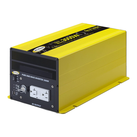
GPSW-1000/2000/3000 ___________________________________________________________ 3. Name and Main Function 3.1 Front view (GPSW3000 and GPSW2000) i) AC outlets a) Ventilation b) On / Off switch c) Input level d) Load level e) Status f) Frequency g) Power save h) Strain relief clamp ... - Page 7 GPSW-1000/2000/3000 ___________________________________________________________ Frequency: Typical North American setting is 60 Hz. Set dip switch S4 to “0” for 50 Hz and “1” for 60 Hz. Power Save: Puts inverter to sleep until a load is present. Strain Relief Clamp: Provides strain relief for Hard Wire AC Output option. AC Outlet: Ground Fault Protected (GFCI) Outlet sockets available: North America.
- Page 8 GPSW-1000/2000/3000 ___________________________________________________________ Ground to vehicle chassis using # 8 AWG wire. Battery terminals: Connect to 12/24 V battery or other 12/24 V power source. [+] is positive and [-] is negative. Reverse polarity connection will blow the internal fuse and may damage inverter permanently. 3.2 GPSW-1000 3.2.1 Front View (GPSW-1000) ON / OFF switch:...
- Page 9 GPSW-1000/2000/3000 ___________________________________________________________ Solid Green: AC power OK Flashing Green Power Saving Active Fast Red Blink: Over voltage protection (OVP) Slow Red Blink: Under voltage protection (UVP) Intermittent Red Blink: Over temperature protection (OTP) Solid Red: Overload protection (OLP) Ventilation Ports: Do not obstruct, allow at least one inch for airflow Frequency: Typical North American setting is 60 Hz.
-
Page 10: Installation
For hook-up, please follow these guidelines: Unpack and inspect your Go Power! Inverter, then check to see that the power switch is in the OFF position. Set up your power output according to Section 10, Configuring your Sine Wave. - Page 11 GPSW-1000/2000/3000 ___________________________________________________________ black terminal is negative (-). Connect the cables into the terminals and tighten the terminal screw to clamp the wires securely. Connect the cable from the negative terminal of the inverter to the negative terminal of the battery. Make a secure connection. Loose connections result in excessive voltage drop and may cause overheated wires and melted insulation.
- Page 12 GPSW2000-24V: Please use 10 ft or less of #2 Cable with a 200 Amp fuse. A GP-DC Kit 4 suitable for 12 V and a GP-DC Kit 3 suitable for 24 V applications is available from Go Power Inc. GPSW3000-12V: Please use 10 ft or less of 4/0 Cable with a 400 Amp fuse.
-
Page 13: Operation
GPSW-1000/2000/3000 ___________________________________________________________ available, the chassis ground lug should be connected to a grounding point, which will vary depending on where the inverter is installed. In a vehicle, connect the chassis ground to the chassis of the vehicle. In a boat, connect the chassis ground lug to the boat's grounding system. - Page 14 GPSW-1000/2000/3000 ___________________________________________________________ approximately 3.0 W from the battery. 5.2 Input Level (battery voltage) indicator The GPSW600, GPSW1000, GPSW2000 and GPSW3000 Input Level LED changes colour from green to yellow to red as battery voltage decreases from a resting voltage of 12.7 V - 10.5 V (12 V) or 25.4 V – 21V (24 V). The Input Level LED changes colour from green to yellow to red as battery voltage increases from a resting voltage of 12.7V –...
- Page 15 GPSW-1000/2000/3000 ___________________________________________________________ Over temperature Red LED blinking Over temperature protection protection intermittently indicates that the inverter has shut itself down because it has become overheated. The inverter may overheat if it has been operated at power levels above its rating or if it has been installed in a location which does not allow it to properly dissipate heat.
- Page 16 GPSW-1000/2000/3000 ___________________________________________________________ 95 W 210 W 115 W 245 W 135 W 280 W To disable power saving, leave dip switches S1, S2 and S3 in the OFF or 0 position. 5.7 What is Power Saving? (GPSW1000, GPSW2000 and GPSW3000) Power saving mode enables the inverter to be “on”...
-
Page 17: Operating Limits
GPSW-1000/2000/3000 ___________________________________________________________ 6.0 Operating limits 6.1 Power output Some induction motors used in refrigerators, freezers, pumps, and other motor- operated equipment require very high surge currents to start. The inverter may not be able to start some of these motors even though their rated current draw is within the power rating of inverter. -
Page 18: Troubleshooting
GPSW-1000/2000/3000 ___________________________________________________________ 7.0 Troubleshooting 7.1 Common problems Television interference: Operation of the power inverter can interfere with television reception on some channels. If this situation occurs, the following steps may help to alleviate the problem: Make sure that the chassis ground lug on the back of the power inverter is solidly connected to the ground system of your vehicle, boat or home. -
Page 19: Maintenance
9.1.1 What the Go Power! Warranty Covers and for How Long Subject to the exclusions and claim procedure set out below, Go Power! warrants for a period of 2 years from the date of purchase at the point-of-sale to the original end-user customer (“Sale Date”), that the Go Power! - Page 20 Product. To exercise this right, the Purchaser shall ship, at its own expense, and return the Product to Go Power! according to the return instructions detailed below, and Go Power! will, repair or replace the Product and return it to the Purchaser free of charge, or offer credit towards the purchase of new Product.
- Page 21 's liability on any claim, whether in warranty, contract, negligence, or any other legal theory, for loss, damage or injury arising directly or indirectly from or in relation to the use of the Go Power! Product shall in no event exceed the purchase price of the Go Power! Product which gave rise to the claim .
- Page 22 Contact your sales representative or Dealer and discuss the problem. Often the sales representative can troubleshoot common scenarios. If applicable, warranty will be handled between the End User and the Dealer. Go Power! will only accept returned items from an End User as a last resort. If you are unable to...
- Page 23 GPSW-1000/2000/3000 ___________________________________________________________ 23 ...
- Page 24 GPSW-1000/2000/3000 ___________________________________________________________ © 2011 GO POWER!™ By Carmanah Technologies www.gpelectric.com MOBI_MAN_GPSW-600-1000-2000-3000_vE_Dec2011 24 ...
Need help?
Do you have a question about the GPSW-3000 and is the answer not in the manual?
Questions and answers