
Related Manuals for Go Power GP-PWM-30


Summary of Contents for Go Power GP-PWM-30
- Page 1 GP-PWM-30 ™ User Manual 30 AMP PWM SOLAR CONTROLLER © 2015 Go Power!® By Carmanah Technologies Solid Signal www.solidsignal.com ® info@solidsignal.com 1.877.312.4547 77727_MANUAL_GP-PWM-30_vE powered by...
-
Page 2: Table Of Contents
Contents 1. Installation Overview ................... 3 Introduction ....................3 1.2 Specifications ..................... 4 2. Warnings ......................5 3. Tools and Materials Needed ..............6 4. Choosing a Location ..................6 5. Installation Instructions ................6 6. Wiring Diagram ....................8 Charging Only One Battery ................ -
Page 3: Installation Overview
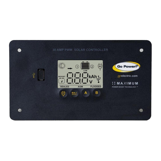
Controller prevents overcharging by limiting the current flowing into the batteries from your solar array. The GP-PWM-30 is a 12-volt flush mounted photovoltaic (PV) charge controller rated for a continuous solar current input of 30 amps. The GP-PWM-30 uses Pulse Width Modulation (PWM) technology and a unique four stage charging system that includes an automatic equalize setting to charge and protect your battery bank (for flooded batteries only). The GP-PWM-30 features an LCD digital display that shows the charge current of the solar array, system battery voltage and battery capacity. -
Page 4: Specifications
The total rated Maximum Power Current (Imp) of the PV input should not exceed 30 amps. The GP-PWM-30 will limit PV current above 30 Amps. Although the GP-PWM-30 will accept PV current greater than 30 Amps for a short duration, damage may occur if the GP-PWM-30 operates continuously with greater than 30 Amps of PV input. -
Page 5: Warnings
PV strings in parallel. The resulting Do not exceed the system Imp current is not to exceed 30A. The GP-PWM-30 amp voltage of the array is the rated open circuit current and max voltage (Voc) of the PV array and is not to voltage ratings exceed 28V. -
Page 6: Tools And Materials Needed
The wire from the solar array most commonly enters the RV through the fridge vent on the roof or by using the Go Power! Cable Entry Plate (sold separately) that allows installers to run wires through any part of the roof. PV connections should connect directly to the controller. - Page 7 Wiring the GP-PWM-30. Wire the GP-PWM-30 according to the wiring schematic in Section 6. Run wires from the solar array and the batteries to the location of the GP-PWM-30. Keep the solar array covered with an opaque material until all wiring is completed.
-
Page 8: Wiring Diagram
Wiring Diagram The GP-PWM-30 is based on a 30 amp max input from the solar modules. E.G. Three modules in parallel with an input of 7 amps each equal a total input of 21 amps. Most solar modules list the input amps on their specifications label. -
Page 9: Charging Two Batteries
Wiring Diagram 6.2 Charging Two Batteries Use the wiring diagram on the next page if you are using the GP-PWM-30 to charge two batteries. First, connect battery 1 to the battery 1 terminals and battery 2 to the battery 2 terminals on the back of the solar controller. Then, connect the solar panel to the controller. -
Page 10: Display Symbols
7. Display Symbols 1. Sun = Daytime: PV Charge Current 6.USB Charging On Moon = Nighttime: No Charge Current (symbol will disappear when charger is off) . Battery 1 or Battery 2 Indication 7. Battery Type Profiles (Sealed/Gel AGM, Flooded) 3. Battery State of Charge Boost Mode (Controller tries to 4. -
Page 11: Operating Instructions
Power Up mode. Icons Displayed: All segments of the numerical display blink Depending on the battery voltage when the GP-PWM-30 Power Up occurs, the controller may do a Boost Charge or quickly go into Float Charge. The Charging Profile selected will commence the following day after a Power Up (refer to the Charging Profile Chart on page 15 for more details). - Page 12 Battery 2 and no status information will be displayed on the LCD screen. Non-volatile memory: Any settings made on the GP-PWM-30 will be saved even when the power has been disconnected from the controller. Refer to the Battery Charge Profile Chart on page 15 for details on each profile.
-
Page 13: Viewing The Controller Display Information
Operating Instructions 8.3 Viewing the Controller Display Information The GP-PWM-30 has two modes to watch the display information, manual and auto scroll.You can change between the two modes by holding down the A Button for 3 seconds. Mode 1- Manually Scroll Through... - Page 14 Symbol (V), Symbol 2. Battery 2 Current Screen Push the B Button to show the PV charging current for battery 2. The GP-PWM-30 will begin to limit the current as the battery 2 reaches a full charge. Icons Displayed: Arrow, Ampere...
-
Page 15: Battery Charging Profile Chart
The terms SEALED/GEL, AGM and FLOODED are generic battery designations. Choose the charging profile that works best with your battery manufacturer’s recommendations. Auto Equalize: The GP-PWM-30 has an automatic equalize feature that Note will charge and recondition your batteries once a month at a higher voltage to ensure that any excess sulfation is removed. Auto equalize is only available for flooded batteries. -
Page 16: Errors
Battery 1 drops below 6 volts (this is because the GP-PWM-30 is powered by Battery 1). Icons Displayed: Battery SOC Symbol, LOW, Symbol 1 or 2 page 16... -
Page 17: Inverter On/Off
9. Inverter Control (On/Off) The following Go Power!® inverters can be turned on/off through the GP-PWM-30 when a modular 6p4c RJ11 type connector is used (included with an optional Go Power!® inverter remote): • GP-SW1000-12 • GP-SW2000-24 • GP-SW1000-24 • GP-SW3000-12 •... -
Page 18: Usb Charging
10. USB Charging The GP-PWM-30 offers a standard USB connector for delivering 5V to small mobile appliances such as cell phones, tablets and small music players. This charging port is capable of supplying up to 800 mA of current. Remove the rubber cover of the USB terminal to access the terminal. -
Page 19: Troubleshooting Problems
There may be a slight difference between the battery voltage displayed on the GP- PWM-30 display and the battery voltage measured at the battery terminals. When troubleshooting using a voltmeter, check both the battery voltage at the GP-PWM-30 controller terminals and battery voltage at the battery terminals. If a difference of more than 0.5 volts is noted, this indicates a large voltage drop possibly caused by loose... - Page 20 4. Blown diode in solar the module may be faulty. module when two 4. Disconnect array wires from Contact the Go Power! or more modules the controller. Take a voltage Technical Support team as are connected in reading between the positive listed in section 13.1 for...
-
Page 21: Limited Warranty
Go Power! electronic products are non-repairable. Go Power! does not perform repairs on its products nor does it contract out those repairs to a third party. Go Power! does not supply schematics or replacement parts for any of its electronic products. -
Page 22: Installation Template
14. Installation Template Use the template on page 23 for flush mounting the controller. page 22...
Need help?
Do you have a question about the GP-PWM-30 and is the answer not in the manual?
Questions and answers