
Related Manuals for TANDBERG MCU


Summary of Contents for TANDBERG MCU
-
Page 1: User Manual
User Manual Software version D3 D12911-03 This document is not to be reproduced in whole or in part without permission in writing from:... - Page 2 TANDBERG MCU...
-
Page 3: Trademarks And Copyright
Our products are low energy consuming products. Waste handling: There is need to send material back to TANDBERG. Please contact your local dealer for information on recycling the product by sending the main parts of the product for disassembly at local electronic waste stations. -
Page 4: Operator Safety Summary
TANDBERG MCU Operator Safety Summary For your protection, please read these safety instructions completely before operating the equipment and keep this manual for future reference. The information in this summary is intended for operators. Carefully observe all warnings, precautions and instructions both on the apparatus and in the operating instructions. -
Page 5: Table Of Contents
Configure the MCU ................41 PRI Configuration ..................41 IP Configuration ..................... 46 H.323 Configuration ..................48 Dataport Configuration .................. 50 SNMP Configuration ..................51 Miscellaneous Configuration ................. 52 Software Upgrade ..................54 MCU Dial In Numbers ..................55 MCU Features ....................56... - Page 6 TANDBERG MCU Dial Profiles ....................57 Conference Template ..................58 File Management ................... 59 Appendices ..................61 Appendix 1: Using the file system ..............61 Appendix 2: Declaration of Conformity ............62 Appendix 3: Capacity ..................63 Index ....................64...
-
Page 7: Introduction
Introduction This User Manual is provided to help you make the best use of your TANDBERG MCU. The MCU enables sites on IP and sites on ISDN to participate in meetings with each other, and at the same time it offers superior quality and ease of use in one fully-featured multipoint control unit (MCU). -
Page 8: The Tandberg Mcu
Yellow Alarm or Remote Alarm Indicator (RAI) means that the MCU is receiving framing info, but in this framing info the other side tells the MCU that it is not reading the MCU’s transmitted framing info. Typically, this may be a broken connector in the transmit (TX) part of the PRI cable. -
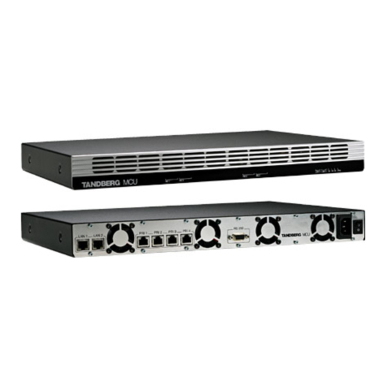
Page 9: Rear View
NOTE CONNECTOR IS NOT USED MCU Capacity – typical scenarios (16 video sites and 16 telephony calls option) Below is an overview of the number of video calls possible to connect on different bandwidths, when 4xE1 (or 4xT1) PRI ISDN lines are connected. In addition to the video calls, telephony calls can also be added. -
Page 10: Installation
- There should be a clearance of 9.1cm between the product and any other product mounted in the rack. Unpacking To avoid damage to the unit during transportation, the MCU is delivered in a special shipping box which should contain the following components: •... -
Page 11: Installation Site Preparations
• Make sure that the MCU is accessible and that all cables can be easily connected. • For ventilation: Leave a space of at least 10cm (4 inches) behind the MCU’s rear panel and 10cm (4 inches) in front of the front panel. -
Page 12: Connecting Cables
CSU between your MCU and the PRI line from your network provider. LAN cable To use the MCU on IP, connect a LAN cable from the ‘LAN 1’ connector on the MCU to your network. The ‘LAN 2’ connector is not used and should be left open. -
Page 13: Mcu Configuration
5. Start a WEB browser and enter the IP-address of the MCU. Default password: ‘TANDBERG’. 6. To configure the MCU for ISDN dial in, enter the PRI numbers and dial in number(s). For details, see the ‘PRI Configuration’ section and the ‘MCU Dial In Numbers’ section under ‘Configure the MCU’. -
Page 14: Mcu Start-Up
TANDBERG MCU MCU start-up To start the MCU, make sure that the power cable is connected, and press the power switch button to ‘1’. On the front panel of the MCU the power indicator LED, marked ‘Pwr’, will now turn GREEN. -
Page 15: Using The Mcu
Conference Shows each active conference. MCU Conference A conference is active. Click on MCU Conference to see conference status in details. It is possible to change the conference name. [Idle] No conference is active. Click on [Idle] to set up a new conference. -
Page 16: Allow Incoming Calls
Shows the call duration of the conference. Allow Incoming Calls Participants can dial in to the conference. No incoming calls are allowed. The MCU must dial out to all participants. Encryption (Secure conference The MCU supports Secure Conference DES and AES. - Page 17 Shows the current status of all the available resources (Video, Telephone, ISDN Channels, Total Bandwidth). Video Calls 4 of 16, indicate that four video calls are connected to the MCU. Maximum is 16. Telephone Calls 0 of 16, indicate that no telephone calls connected to the MCU. Maximum is 16.
-
Page 18: Set Up A New Conference
TANDBERG MCU Using the MCU Set up a new conference To set up a new conference, click on ‘Conference 1, 2 or 3’ to begin a new conference. Shown below is the set up for ‘Conference 3’. O MODIFY THE DEFAULT CONFERENCE TEMPLATE ‘C... -
Page 19: Conference Configuration
Overview’ page and on the ‘Conference Status’ page. Default Call Type Specifies the default call rate that the MCU shall use when dialing to a participant. It is also the maximum rate allowed in the conference. If a participant does not support this rate, the MCU will connect at the highest rate possible. - Page 20 When connecting older videoconferencing endpoints to the MCU, problems can occur since older equipment sometimes do not handle modern capabilities. When selected, some capabilities are not being sent from the MCU. Please refer to the software release document for more information.
- Page 21 30 frames per second (fps). In Continuous Presence 5+1, 7+1, 9 and 16 mode, the MCU will select ‘Motion (CIF)’ if the call rate is below 256 kbps and ‘Sharpness (4CIF)’ when the call rate is 256 kbps or higher.
- Page 22 Allow G.728 The MCU supports high quality audio even on low call rate. On low call rate the MCU will prioritize G.722.1. Video participants not supporting this, will receive low quality audio G.728 instead, when ‘Allow G.728’ is selected. To ensure high quality audio on low call rate, unselect ‘Allow G.728’...
- Page 23 After entering the correct password and confirming (typically by pressing ‘OK’), the participant will join the conference. When using DTMF tones, the MCU will automatically accept the password without having to press a confirmation key. Should the password be incorrect, the participant is met with the ‘Password Incorrect’...
- Page 24 Add Participants Selecting ‘Add Participants’ will create a conference with the above-specified configuration and at the same time, the MCU will open the ‘Add Participants’ page. Here the conference administrator can add participants from the phone book or manually dial one.
-
Page 25: Manage An Active Conference
Shows the conference ISDN and IP dial in number. Each conference has separate dial in numbers. Call Duration Shows the call length of the current conference. Video Out Shows the outgoing video rate, video encoding algorithm and resolution that is transmitted from the MCU to the participants. - Page 26 ‘Cascading Slave’ indicates that this conference has become Slave when connecting to another MCU. Conference Snapshot Shows a snapshot of the video transmitted from the MCU to the participants. Click on the picture to enlarge it in a separate window. DuoVideo Snapshot Shows a snapshot of the DuoVideo transmitted from the MCU to the participants.
-
Page 27: Disconnect All
TANDBERG MCU Using the MCU Add Participants To add new participants to the conference, press ‘Add Participants’ and the ‘Add Participants’ window is shown. Select the participant(s) from the Phone book and press ‘Call Participants’. If a participant is not listed, use the ‘Manual Dial’... -
Page 28: End Conference
Status Shows the status of the connection. Establ Out Shown during call setup between the participant and the MCU. Alerting Waiting for the participant to answer the outgoing call. Connected, 384 kbps The participant is connected at 384 kbps bandwidth. - Page 29 The participant has either disconnected or been disconnected by the conference administrator. Clear Out The MCU is currently disconnecting the participant. Shows the network protocol used for the connection. H323 The participant is connected on IP using the H.323 protocol.
- Page 30 TANDBERG MCU Using the MCU DuoVideo Shows the DuoVideo status for each participant. The participant is transmitting DuoVideo. The participant is receiving DuoVideo. In Picture Shows the current Picture Mode and where each participant is displayed in the outgoing video image from the MCU.
-
Page 31: Advanced View
To mute a participant, press the ‘Mute Site’ button and the participant will not be heard by the other participants. Note that muted participants will not be able to ‘un mute’ themselves, since this is done on the MCU. The participants can independently of this function, mute their microphone locally on their system. -
Page 32: Terminal List
TANDBERG MCU Using the MCU Terminal List List the participants in the conference. If the conference is cascaded to another conference, this is also shown here. -
Page 33: Manage The Phone Book
Manage the Phone Book By selecting the ‘Phone Book’ tab, you can add new or edit existing Phone Book entries in the MCU. The Phone Book can be used to dial out to a participant, either through ISDN or IP, and can contain up to 99 single entries and 16 group entries. -
Page 34: Add New Entry
Video number or telephone number. Call Type Select the call rate to be used. For details, see the ‘Set up a new conference’ section under ‘Using the MCU’. 2nd Number If two numbers are required, both should be specified (2x64 kbps, 2x56 kbps calls). -
Page 35: Add New Group Entry
TANDBERG MCU Manage the Phone Book Add New Group Entry It is possible to define up to 16 group entries. The Group entries are useful for recurring meetings where the same participants meet each time. By doing this, only the group entry has to be selected in the ‘Add Participants’... - Page 36 TANDBERG MCU Manage the Phone Book Edit Entry To edit an entry in the Phone Book, press the ‘Edit’ button and the ‘Edit Entry’ will open, as shown in the figure below. By selecting an existing Entry in the Phone Book and then pressing the ‘Edit’ button, you will be able to edit the selected entry.
-
Page 37: View System Status
TANDBERG MCU System Status View System Status To view current MCU status, open ‘System Status’ as shown in the figure below. PRI Status To view status of the PRI, open ‘PRI Status’ as shown in the figure below. If a participant has been disconnected, the cause code can be viewed by pressing the link next to the PRI... -
Page 38: Pri Alarms
Yellow Alarm or Remote Alarm Indicator (RAI) means that the MCU is receiving framing info, but in this framing info the other side tells the MCU that it is not reading the MCU’s transmitted framing info. Typically, this may be a broken connector in the transmit (TX) part of the PRI cable. -
Page 39: H.323 Status
‘Inactive’ means the MCU is not registered to a gatekeeper. ‘Registering’ means the MCU is having problems registering with the selected gatekeeper. System Information To view MCU information, open ‘System Information’ as shown in the figure below. This page provides information on installed software and hardware. -
Page 40: Available Resources
TANDBERG MCU System Status Available Resources To view available resources on the MCU, open ‘Available Resources’ as shown in the figure below. -
Page 41: Configure The Mcu
TANDBERG MCU Configure the MCU Configure the MCU To Configure the MCU, open ‘System Configuration’ and ‘MCU Configuration’. Shown in the figure below is the ‘System Configuration’. PRI Configuration To configure the PRI settings on the MCU, open ‘PRI’ as shown in the figure below. -
Page 42: Parallel Dial
Send Own Number The MCU will send its own number to the far end. The MCU will not send its own number to the far end, but please note that the network may still send your number to the far end. - Page 43 TANDBERG MCU Configure the MCU NSF Example: AT&T offers several digital switched services. These include SDN with service code 1 and ACCUNET with service code 6. Example: Service profiles for Sprint: Below is a list of common service profiles. As these profiles...
-
Page 44: Interface Configuration
However, if PRI Trunk Grouping is enabled, the number range for PRI 1 will also apply for PRI 2, 3 and 4. Number Range Start The PRI lines connected to the MCU should have at least one number each, to allow dial in from ISDN. If the PRI line has a range of numbers, the start number must be entered here. -
Page 45: Channel Hunting
• If you have a PRI with only 12 channels. Set Max channel to 12. Max Channels Indicates the maximum number of B-channels the MCU is allowed to use for each of the PRI-interfaces. For E1 (ETSI/Euro ISDN), the maximum number of channels is 30. For T1 (National ISDN and AT&T Custom), the maximum number of channels is 23. -
Page 46: Ip Configuration
TANDBERG MCU Configure the MCU IP Configuration To configure the IP settings on the MCU, open ‘IP’ as shown in the figure below. Configuration IP Address Assignment DHCP: Dynamic Host Configuration Protocol can be selected when a DHCP server is present. Static IP Address, Static IP Subnet Mask and Static IP Gateway are ignored because these parameters are assigned by the DHCP server. - Page 47 Configure the MCU Static IP Address The Static IP Address defines the network address of the MCU. This address is only used in static mode. Your LAN administrator will provide you with the correct address for this field. Static IP Subnet Mask The Static IP Subnet Mask defines the type of network.
-
Page 48: H.323 Configuration
TANDBERG MCU Configure the MCU H.323 Configuration To dial in to a conference from IP requires the use of H.323 numbers (E.164 aliases). This means that the MCU must be registered to a Gatekeeper. H.323 G ATEKEEPER TATUS SHOWS CURRENT STATUS OF ATEKEEPER REGISTRATION H.323 Configuration... -
Page 49: Quality Of Service
The network must support Quality of Service for these settings to work. RSVP No RSVP Quality of Service is initiated for any connections. Auto Resource Reservation Protocol enables the MCU to request the optimal amount of bandwidth for the duration of an IP video call. QoS Mode No QoS is used. -
Page 50: Dataport Configuration
BE A STRAIGHT THROUGH RS232 CABLE Dataport Configuration is used to configure the RS 232 serial port on the MCU. If you want to connect a PC to the dataport, you must ensure that the PC and the MCU are identically configured. Configuration... -
Page 51: Snmp Configuration
SNMP or Simple Network Management Protocol is used for monitoring and configuring different units in a network. The MCU’s SNMP Agent responds to requests from SNMP Managers (a PC program etc.). SNMP traps are generated by the agent to inform the manager about important events. -
Page 52: Miscellaneous Configuration
To delete the existing password, select ‘Delete Password’. Services The different IP services on the MCU - FTP, Telnet, Telnet Challenge, HTTP, HTTPS and SNMP can be independently disabled to prevent access to the MCU. In addition, the SNMP Service Read Only/Traps Only will make it possible to read SNMP messages in addition to... - Page 53 This function will notify any Management Application, such as TANDBERG Management Suite, if anyone tries to perform Remote Management on the MCU using an illegal password. The Security alert that is sent to the Management Application will contain information about the IP address and the service (WEB, Telnet, FTP) being used for the attempt.
-
Page 54: Software Upgrade
TANDBERG MCU Configure the MCU Software Upgrade Software upgrade is where new software to the MCU can be installed. It also shows the current software version and the MCU’s hardware serial number. MCU, NOTE O UPGRADE THE VALID ELEASE EY AND... -
Page 55: Mcu Dial In Numbers
TANDBERG MCU Configure the MCU MCU Dial In Numbers To configure the dial in number for each conference, open ‘MCU Dial In Numbers’ as shown in the figure below. H.323 N O USE THE UMBERS NOTE (E.164 A LIAS MUST BE REGISTERED TO A... -
Page 56: Mcu Features
MCU Features Experience has shown that new standardized features might cause interoperability problems between legacy video conferencing products. If you disable features on this page, the MCU can be used as a filter to ensure interoperability with legacy products. To configure the MCU features, open ‘Features’ as shown in the figure below. -
Page 57: Dial Profiles
Configure the MCU Dial Profiles Specifies the service prefix which the MCU must use when dialing out. Example: If you have to use ‘0’ in order to call outside your location, create a profile called ‘Ext’ with a prefix set to ‘0’. -
Page 58: Conference Template
TANDBERG MCU Configure the MCU Conference Template The Conference Template is the settings that will be used as default settings when creating new conferences. O LEARN MORE ABOUT EACH ‘S SETTING SEE THE ET UP A ’ ONFERENCE SECTION ‘U MCU’. -
Page 59: File Management
TANDBERG MCU Configure the MCU File Management The File Management allows viewing or changing pictures and sounds shown to the participant when connecting to the MCU. NOTE LEASE REFER TO THE ‘L ’ EGAL YPES FIELD AT THE BOTTOM OF... - Page 60 TANDBERG MCU Configure the MCU Clicking on ‘System Parameters’ allows users to backup the system configuration, which may be restored at a later time. Clicking on ’Directory’ allows users to save the directory file, which can be useful for backup purposes, and...
-
Page 61: Appendices
TANDBERG MCU Appendices Appendices Appendix 1: Using the file system It is possible to access a file system within the TANDBERG MCU by using ftp: DOS-window: ftp <IP-address of MCU>, or Web-browser: ftp:// <IP-address of MCU> Description of the different files all.prm... -
Page 62: Appendix 2: Declaration Of Conformity
Appendices TANDBERG MCU Appendix 2: Declaration of Conformity... -
Page 63: Appendix 3: Capacity
Example: If the MCU has made 6 calls at 768, 4 calls at 384, and 4 encrypted calls at 192 the calculation will be: 6x62 + 4x46 + 4x60 = 372 + 184 + 240 = 796. Since 796 is less than 845, this will be possible. -
Page 64: Index
Manage the Phone Book 33 Conference Name 19 Floor to Full Screen 20 Max Call Duration 19 Conference Overview 15 Front view of MCU 8 Max Channels 45 Conference Password 23 MCU Configuration 13 Conference Snapshot 26 MCU Dial In Numbers 55... - Page 65 Telephone Noise Suppression 22 Miscellaneous Configuration 52 Telephone Participant Limit 24 Rack Mounting (optional) 11 Terminal List 32 Rear view of MCU 9 The TANDBERG MCU 8 Release Key 54 Trademarks and copyright 3 Natural Video 46 Restart of MCU 53...
Need help?
Do you have a question about the MCU and is the answer not in the manual?
Questions and answers