
Related Manuals for AMX Epica DGX 32


Summary of Contents for AMX Epica DGX 32
-
Page 1: Instruction Manual
Instruction Manual Epica DGX 32 Distribution Matrix A u t o P a t c h M a t r i x S w i t c h e r s R e l e a s e : 3 / 1 9 / 2 0 1 0... - Page 2 Partner which include AMX Dealers, Distributors, VIP’s or other AMX authorized entity. AMX warrants its products to be free of defects in material and workmanship under normal use for three (3) years from the date of purchase, with the following exceptions: •...
-
Page 3: Table Of Contents
Technical Support........................40 Connecting to NXB-AP-1000 Server (TCP/IP Port) ..............40 Epica DGX 32 SC Optical Boards ..............45 Specifications Epica DGX 32 SC Optical Boards..............46 System Setup with DGX Modules..................47 Safety Recommendations for Laser Products ................ 48 Attaching Cables ........................48 Epica DGX 32 DVI Boards .................51... - Page 4 Determining the Need for EDID Programming..............104 Installing the EDID Programmer ..................104 Reading and Saving EDID Data from a Destination Device ..........105 Writing EDID Data to Epica DGX 32 DVI Input Connector ..........106 Epica DGX 32 Instruction Manual...
- Page 5 Using BCS to Access System Diagnostic Information ............134 Splash Screen Examples ...................... 135 Appendix E – Board Replacement ..............137 Procedure Overview......................137 Safety Recommendations for Laser Products ..............137 Replacing or Adding a Board ....................138 Board Troubleshooting......................140 Epica DGX 32 Instruction Manual...
- Page 6 Contents Epica DGX 32 Instruction Manual...
-
Page 7: Esd Warning
Grounding straps, conductive smocks, and conductive work mats are specifically designed for this purpose. Anyone performing field maintenance on AMX AutoPatch equipment should use an appropriate ESD field service kit complete with at least a dissipative work mat with a ground cord and a UL listed adjustable wrist strap with another ground cord. -
Page 8: Important Safety Information And Instructions
There are no user serviceable parts inside an AMX AutoPatch product; service should only be done by qualified personnel. If you see smoke or smell a strange odor coming from your AMX AutoPatch product, turn it off immediately and call technical support. -
Page 9: Information Et Directives De Sécurité Importantes
Placez uniquement des fusibles de calibre exact dans les boîtiers. Veillez à ce que la prise de courant soit proche de l’appareil et facile d’accès. Veillez à ce que votre appareil AMX AutoPatch soit installé sur une surface stable ou qu’il y soit fermement maintenu. -
Page 10: Notices
AMX. Copyright protection claimed extends to AMX hardware and software and includes all forms and matters copyrightable material and information now allowed by statutory or judicial law or herein after granted, including without limitation, material generated from the software programs which are displayed on the screen such as icons, screen display looks, etc. - Page 11 Warning: The icon to the left indicates text that warns readers against actions or conditions that could cause potential injury to themselves. Caution: The icon to the left indicates text that cautions readers against actions that could cause potential injury to the product or the possibility of serious inconvenience. Epica DGX 32 Instruction Manual...
- Page 12 Notices Epica DGX 32 Instruction Manual...
-
Page 13: Overview And General Specifications
Epica DGX 32 Enclosure (6 RU) Configuration FG # Model 32x32 FG1056-32 AVS-EPDGX32-ENC Epica DGX 32 Pre-Engineered Systems (DVI Only) Note: All of Epica DGX 32 pre-engineered systems contain DVI Input and Output Boards only. Configuration FG # Model 16x16 FGP56-1616-DD0 AVS-EPDGX32-1616-DD0 16x24... -
Page 14: Product Notes
Overview and General Specifications Product Notes The Epica DGX 32 is available in both pre-engineered (DVI only) and custom systems in a variety of input to output configuration sizes and can contain an assortment of input and output boards in a single enclosure. -
Page 15: Front View
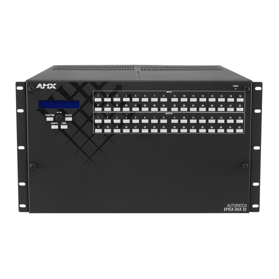
Note: Features and specifications described in this document are subject to change without notice. Front View The enclosure, which is the structural basis of the Epica DGX 32 Distribution Matrix, can be controlled using the standard front control panel, control software, or an external controller (for additional information on control options, see page 13). -
Page 16: Rear View
CPU/Control board Serial number FIG. 2 Rear view of an Epica DGX 32 enclosure Rear View Components Input and output boards (some slots may be empty, depending on the configuration) 2 non-functional slots (not designed for input or output boards) -
Page 17: Power Supply Units
DGX Fiber Modules used in the conversion process for the DGX 32 SC Optical boards. Epica DGX 32 enclosures have 16 vertical board slots (8 slots each for input and output boards with four connectors each), allowing for a maximum configuration of 32x32. -
Page 18: Epica Dgx 32 General Specifications
Approximately 70 lb. (31.8 kg) per loaded enclosure Compatible Fiber Modules AMX AutoPatch DGX Fiber TX and DGX Fiber RX modules For individual board information and specifications, see the specific board chapter in this manual. DGX SC Optical Boards – see page 45 DGX DVI Boards –... -
Page 19: Configuration Information And Control Options
Note: The Epica DGX 32 supports full Device Discovery through AMX’s AutoPatch Duet module (see page 119). Control Panel The control panel (see page 55) is standard on all Epica DGX 32 enclosures. Besides the control panel, the following external methods of control are available. AMX Control Devices The Epica DGX 32 is compatible with a number of AMX control devices via Native NetLinx communication. - Page 20 * For information on BCS commands, see the BCS Protocol Instruction Manual on the AMX AutoPatch CD or at www.amx.com. Third-Party Controllers A third-party controller can also be attached to an Epica DGX 32 enclosure via the RS-232 serial port. If using a third-party controller, see the controller documentation for operating instructions. XNNet Protocol Advanced programmers who want to design their own control programs can use XNNet protocol.
-
Page 21: Installation And Setup
FIG. 6 Caution label for Class 3R laser products Important: No user serviceable parts are included inside an AMX AutoPatch product; service should only be done by qualified personnel. Caution: Use of controls or adjustments or performance of procedures other than those specified herein may result in hazardous radiation exposure. -
Page 22: Site Recommendations
These recommendations address potential hazards that are common to all installations: Elevated Operating Temperature The maximum rated ambient temperature for Epica DGX 32 enclosures is 113° F (45° C). All equipment should be installed in an environment compatible with the manufacturer’s maximum rated ambient temperature. -
Page 23: Unpacking
After powering up the enclosure, apply power to the source and destination devices. Unpacking The Epica DGX 32 is shipped with one enclosure per shipping box. The invoice is sent separately; a packing slip is attached to the outside of each box. Each box contains the following items:... -
Page 24: System Setup Options
SC Optical DVI RX A typical system setup is illustrated on page 47 and shows an Epica DGX 32 with DGX SC Optical Boards used in conjunction with a DGX TX and a DGX RX. The DGX HD-15 TX and the DGX DVI TX modules can be installed interchangeably. The DGX HD-15 RX and the DGX DVI RX modules are interchangeable as well, providing for an extremely flexible system. -
Page 25: Installation Procedure
Note: If desired, remove rubber feet from bottom of enclosure before rack installation. To install and setup an Epica DGX 32 (requires a minimum of two people): Select a position in the rack for the Epica DGX 32 that is accessible and does not restrict airflow (see Caution above). - Page 26 10. If applicable – Use the EDID Programmer.* * EDID Programmer software can be used for re-programming the DGX DVI Input Boards if necessary (see page 103). This software is located on the AMX AutoPatch CD (also available at www.amx.com). Additional Setup Additional setup tasks may include the following:.
-
Page 27: Linking Enclosures
Replace the connector numbering plate that was removed in Step 1. Linking Enclosures The Epica DGX 32 can link to another Epica DGX 32 or to most other types of AMX AutoPatch Distribution Matrices (see the first table on the next page). - Page 28 AMX provides link cables and equipment for enclosures that are ordered as part of a linked system. The Epica DGX 32 can link to another Epica DGX 32 or to other AMX AutoPatch Distribution Matrices using the cable and equipment specified in the table below. A Multi-Port (8 or 5) Switch is also provided for some types of multiple-enclosure systems.
- Page 29 Linking Epica DGX 32 to Enclosure with RJ-45 Link Connector An Epica DGX 32 can be directly linked to another Epica DGX 32, an Epica DGX 144, Epica DG, Optima, Optima SD, or to a Precis SD enclosure via their 10Base-T Ethernet ports using an RJ-45 cable.
- Page 30 Linking Epica DGX 32 to Enclosure with BNC Link Connector (Also BNC Daisy Chain) An Epica DGX 32 enclosure can be linked to an enclosure with an Ethernet 10Base-2 (BNC) connector (Modula, Modula CatPro, Epica-128, or Epica-256) by using a Media Converter, RJ-45 cable, and RG-58 coax cable.
- Page 31 Multi-Port Switch (or hub) for linking enclosures, contact your network administrator. To link an Epica DGX 32 enclosure to a Multi-Port Switch: Insert one end of the RJ-45 cable into an Enc Link (RJ-45) Ethernet port on the Epica DGX 32 enclosure.
- Page 32 * Applies to Modula, Modula CatPro, Epica-128, and Epica-256 enclosures. ** The total length of all RG-58 coax cables between the Media Converter and the last enclosure in the daisy chain cannot exceed 10 ft. (3.05 m). Epica DGX 32 Instruction Manual...
-
Page 33: Attaching External Controllers
Installation and Setup Attaching External Controllers The Epica DGX 32 can be controlled externally by attaching a control device that uses one of the communication protocols listed below: BCS (Serial) – ASCII sent over a null modem serial cable via the serial port BCS (USB) –... - Page 34 Plug the other end of the serial cable into the serial port on the serial controller. If not already on, apply power first to the Epica DGX 32 enclosure and then to the source and destination devices (see “Applying Power and Startup” on page 34).
- Page 35 (default settings) for serial communication with an Epica DGX 32 Distribution Matrix are provided in the table above. Epica DGX 32 enclosures support baud rates of 9600 (default), 19200, 38400, and 57600. The settings on the PC serial communication software and the enclosure must correspond to each other. If a change is required to make them match, changing the PC’s settings is preferable.
- Page 36 Note: The following dialog boxes appear only during the initial USB connection. Once the virtual Com port has been assigned to the Epica DGX 32, the dialog boxes do not appear again. If they do appear, you have connected the USB plug to a different Com port than the initial one – either switch to the initial Com port or establish a virtual Com port for the new port on the PC.
- Page 37 The Found New Hardware Wizard opens with the default selected to automatically install the software. (The dialog boxes may differ slightly from those shown, depending on the operating system for the PC.) Insert the AMX AutoPatch CD into the PC’s CD holder. Click Next. Click Finish when prompted to close the wizard.
- Page 38 USB connector with the assigned virtual Com port. The PC will not recognize the Epica DGX 32 if you disconnect and reconnect using a different Com port on the PC. However, it will attempt to install a new virtual Com port using the new port. If completed, the new port will be assigned a different Com number.
-
Page 39: Attaching Input And Output Cables
When attaching input and output signal cables in a multiple-enclosure system, check the system and enclosure numbers are on the rear of the Epica DGX 32 (if not on the rear, the numbers are on the side). The system was programmed at the factory to operate only as a specifically configured system. -
Page 40: Applying Power And Startup
Epica DGX 32, we recommend cabling the primary Epica DGX 32 power feed, via a power strip to an outlet connected to one circuit breaker and the redundant power feed via a power strip to an outlet connected to a second circuit breaker (FIG. - Page 41 Execute a test switch (see page 38). (For startup information on specific types of control, see page 36 before executing a test switch.) 10. Attach the remaining sources and destinations and apply power to them. Epica DGX 32 Instruction Manual...
-
Page 42: Serial Control Device Startup
100 Mbps (on) or 10 Mbps (off) * IOS (Initial Operating System) is the base layer operating system on AMX AutoPatch equipment. IOS performs functions such as hosting higher level run-time software applications. When unexpected critical errors are encountered within such hosted applications, system control of the equipment may be passed to the IOS layer preventing normal system operation until the error is manually cleared. -
Page 43: Redundant Power Supply (Rps)
Ready FIG. 20 Power-up splash screen in HyperTerminal Note: AMX reserves the right to add to the contents of the splash screen at any time, without notice. Redundant Power Supply (RPS) Each enclosure ships with two mutually-redundant (hot-swappable) power supplies. -
Page 44: Executing A Test Switch
Directions for establishing an NXB-AP-1000 Server connection for control via the TCP/IP port start on page 40. AMX Controller For executing and disconnecting switches using an AMX Controller, see the instruction manual for the specific device. APControl 3.0 Directions for executing and disconnecting switches using APControl 3.0 are found in its Help file. - Page 45 Verify that the source signal is present (visible and/or audible) at the destination. For a complete list of BCS commands and responses, see the BCS Protocol Instruction Manual on the AMX AutoPatch CD or at www.amx.com. Test Switch Troubleshooting If the test switch did not execute correctly: Check the power indicator on the front of the enclosure.
-
Page 46: Technical Support
Distribution Matrix connected to a LAN. Both computers in the illustration have access to the Epica DGX 32, as does the NetLinx Controller. If only one computer will be used, the Epica DGX 32’s TCP/IP port can be connected directly to the computer’s network card, in which case the NetLinx Controller is also connected directly to the PC. - Page 47 Computer Connection (NIC card) – an RJ-45 cable (either crossover or straight-through) is required to connect the Epica DGX 32 enclosure directly to a network card in a computer. LAN Connection – an RJ-45 cable (either crossover or straight-through) is required to connect the Epica DGX 32 enclosure to a LAN.
- Page 48 Check the indicator LEDs for the TCP/IP connector (see page 41). Follow the instructions for accessing Zero-Config information in the NetLinx Studio WebConsole (see below). Make note of the IP address for the Epica DGX 32 (you will need the IP address for the test procedure below).
- Page 49 All power, signal, and link connections on all of the equipment. LED indicators for the TCP/IP (RJ-45) connector on the rear of the Epica DGX 32. If the LED indicators are not illuminated, check the cable type to make sure it meets cable requirements (see page 41).
- Page 50 Installation and Setup Epica DGX 32 Instruction Manual...
-
Page 51: Epica Dgx 32 Sc Optical Boards
Epica DGX 32 SC Optical Boards FIG. 25 Epica DGX 32 enclosures are built to hold up to sixteen DGX SC Optical Boards with four inputs or outputs per board. Each enclosure holds a maximum of eight input and eight output boards, accommodating connector configurations up to a maximum of 32x32, as well as subsets (for example, 12x24 or 32x8). -
Page 52: Specifications Epica Dgx 32 Sc Optical Boards
Note: Either Transmitter (TX) module can be used in conjunction with either Receiver (RX) module. Epica DGX 32 SC Optical Specifications Parameter Value Compatible AMX AutoPatch Fiber Products DGX HD-15 TX and RX, DGX DVI TX and RX, other AMX AutoPatch DGX SC Fiber signal management products Signal Types over Fiber... -
Page 53: System Setup With Dgx Modules
Epica DGX 32 SC Optical Boards System Setup with DGX Modules DGX SC Optical Input and Output Boards are used in conjunction with AMX AutoPatch DGX Fiber TX and RX modules. Compatible DGX Fiber modules are listed on page 46. A table with system setup options is on page 18. -
Page 54: Safety Recommendations For Laser Products
Attaching Cables Instructions for attaching AMX AutoPatch cable management bars are on page 21. These bars are recommended and provided with each DGX SC Optical Board. Caution: Do not severely bend or kink the SC fiber cable. Irreversible damage can occur. Refer to the physical limitations (bend radius) specified for the cable. - Page 55 FIG. 27 Tie the SC fiber cable to the cable management bar far enough below the connector to allow for the manufacturer’s recommended bend radius. The bend radius for AMX SC terminated fiber cables is 2 inches (5 cm). Repeat the previous steps for the remaining fiber cables.
- Page 56 Epica DGX 32 SC Optical Boards Epica DGX 32 Instruction Manual...
-
Page 57: Epica Dgx 32 Dvi Boards
Epica DGX 32 DVI Input and Output Boards Epica DGX 32 enclosures are built to hold up to sixteen DGX DVI Boards with four inputs or outputs per board. Each enclosure holds a maximum of eight input and eight output boards, accommodating connector configurations up to a maximum of 32x32, as well as subsets in increments of four (e.g., 12x16 or 24x8). -
Page 58: Specifications Epica Dgx 32 Dvi
1024x768 60 Hz, 70 Hz, 75 Hz, 87 Hz 1280x1024 75 Hz ** Some monitors may not support the maximum refresh rate. AMX reserves the right to modify its products and their specifications without notice. Epica DGX 32 Instruction Manual... -
Page 59: Attaching Cables
Epica DGX 32 DVI Boards Attaching Cables To connect DVI inputs and outputs: Fasten the DVI-I (or DVI-D) connectors on the cable ends onto the DVI-I receptacles on the boards. (For DVI pinout information, see below.) DVI-I connector FIG. 29... - Page 60 Epica DGX 32 DVI Boards Epica DGX 32 Instruction Manual...
-
Page 61: Control Panel Operation
Control Panel Operation Overview The Epica DGX 32 Control Panel (standard on all enclosures) is used for controlling the system’s switches and system attributes. Note: AMX AutoPatch software can also be used to control a system; for more information on control options, see page 13. - Page 62 Take Key is pressed. Note that Keys 21 through 24 in the second row of inputs are not available. Key flashing white (input selected) Keys not illuminated (inputs not available) Blue keys Blue keys White keys (outputs available) (outputs available) (outputs selected) Example of key states during Change Mode FIG. 32 Epica DGX 32 Instruction Manual...
- Page 63 Locking the panel limits access which can prevent accidental switches (see page 70). Adjust Audio This menu item will not display unless the Epica DGX 32 is linked to an enclosure that supports audio functions. Selecting Adjust Audio accesses the Adjust Audio submenu. From this menu, you can place the panel in Output Volume Mode, Mute/Unmute Mode, or Input Gain Mode (see page 66).
- Page 64 Executing a command: press the Take Key. Labeling Input and Output Keys Each Epica DGX 32 system ships with a kit for custom labeling. Additional kits may be ordered separately. The Control Panel Label Kit (KA1056-01) includes: Perforated card stock sheets –...
-
Page 65: Executing Switches
To execute a test switch: Press the Function Key. The Function menu appears. Press the Select Key to choose Change. The system is in Change Mode (the available Input and Output Keys turn blue). Virtual matrix Epica DGX 32 Instruction Manual... -
Page 66: Changing The Virtual Matrix
VM 1 = “Video.” The system also supports any custom virtual matrices created in XNConnect; 2 digits are the maximum allowed (0 through 99). VM 0 is the factory default, and for the Epica DGX 32, VM 0 normally routes the same as VM 1. If you create a custom configuration, you will need to change the virtual matrix on the control panel to execute switches (or other operations) using the custom virtual matrix. -
Page 67: Disconnecting Switches
Inputs and outputs can be selected in the same disconnect command. You can disconnect inputs or outputs from the Epica DGX 32 Control Panel using the steps below. If you need to change the virtual matrix, see “Changing the Virtual Matrix” on page 60. -
Page 68: Verifying Signal Status
Or press the Function Key to return to the Function menu. Verifying Signal Status The status of inputs or outputs can be checked using the Epica DGX 32 Control Panel. Signal status can be verified to confirm that a switch has executed properly or to confirm correct routing to multiple outputs (destinations). -
Page 69: Defining And Executing Global Presets
That system state can be restored at any time by selecting the assigned global preset number. Global presets can be defined or recalled using either the Epica DGX 32 Control Panel or BCS commands interchangeably. The Epica DGX 32 Control Panel supports up to 64 global presets. - Page 70 Press either the Select Key or the Take Key. Global Preset 3 is executed. The system returns to the Global Preset submenu. Press the Function Key to return to the Function menu. Note: Status is not invalidated by global presets. Epica DGX 32 Instruction Manual...
-
Page 71: Executing Local Presets
Local presets are not programmed (defined) at the factory. To program them, use XNConnect configuration software (see page 116) or contact your AMX representative (for contact information, see page 40). Once the local presets have been defined as part of the configuration file, the new file must be loaded to the system’s CPU (see page 118) and reloaded to the control panel (see page 73). -
Page 72: Adjusting Audio
Some audio boards in AMX AutoPatch Distribution Matrices offer optional volume control and digital input gain adjustment features. If your Epica DGX 32 system is linked to an enclosure that contains these boards, output volume or digital input gain can be adjusted using either the Epica DGX 32 control panel or BCS commands sent through a serial controller. - Page 73 Note: If the selected output is muted, “Muted” displays as the current setting. Turning the Control Dial will un-mute a muted output and adjust the Volume. To reapply mute, see the next page). FIG. 34 Example of muted output in Output Volume Mode Epica DGX 32 Instruction Manual...
- Page 74 Control Panel Operation Muting and Un-Muting Outputs This feature will work only for an enclosure linked to the Epica DGX 32 that supports volume control. Note: The mute/un-mute option applies to output volume only and is not available for input gain.
- Page 75 If adjusting input gain for a single input – Repeat Steps 7 and 8 for the desired input. 10. Press the Cancel Key to return to the Adjust Audio submenu. Press the Function Key to return to the Function menu. Epica DGX 32 Instruction Manual...
-
Page 76: Locking And Unlocking
Control Panel Operation Locking and Unlocking Locking the Epica DGX 32 Control Panel prohibits access to the system and can prevent accidental switching. While the panel is locked, BCS commands still work; however, they cannot be used to unlock the panel. The panel remains locked if the power is cycled. -
Page 77: Setup Options
– software version of the initial operating system (IOS) for the Control Panel XNet ID – Control Panel’s XNNet device number Use the following steps to check the software version information for the Epica DGX 32 Control Panel. To check the software version information: Press the Function Key. - Page 78 Default Virtual Matrix The factory default virtual matrix for the Epica DGX 32 is VM 0. You have the option of changing the factory default virtual matrix for your system. When you choose a new default virtual matrix, the system will revert to that virtual matrix each time the system is powered up even if you changed the virtual matrix using the V.Matrix list during normal operation.
- Page 79 C o n f i g Press the Select Key. The configuration file reloads to the control panel and the display returns to the top of the Setup Options submenu. Press the Function Key to return to the Function menu. Epica DGX 32 Instruction Manual...
-
Page 80: Setting The Password
Setting the Password The Epica DGX 32’s default password is “1 2 3 4 5” entered using the first five input keys. A new password can be set using any combination of five of the Input Keys 1 through 8 when the LCD displays “Enter New PWD”... -
Page 81: System Error Codes And Troubleshooting
This section provides an overview of the most common error codes that may appear on an Epica DGX 32 Control Panel. The table on the next page lists the error code, the name of the code, the meaning of the code, and some basic troubleshooting strategies (additional error code troubleshooting strategies are included on page 76). - Page 82 In other cases, the command has specified a value that is not valid (e.g., a global preset number that does not correspond to a defined global preset). If the error code persists after correcting and resending the command, contact technical support (see page 40). Epica DGX 32 Instruction Manual...
-
Page 83: Nxb-Ap-1000 Interface - Initial Setup By Network Admin
Internet browsing software. The Epica DGX 32 is connected via an RJ-45 link cable to a LAN (Local Area Network), the Internet, or a network card in a PC (which could then connect to a LAN or the Internet). For installation and link cable information, see page 40. -
Page 84: Opening The Nxb-Ap-1000 Interface
NXB-AP-1000 Interface offers a single, remote access point to a system, and its interactions with that system can cause interference and collision issues if more than one NXB-AP-1000 Interface is present. Note: The instructions in this chapter assume that all of the AMX AutoPatch devices in the system are connected and powered up. -
Page 85: Navigating The Nxb-Ap-1000 Interface
Zero-Config. Assuming that the Epica DGX 32 resides on the same LAN as the PC running NetLinx Studio and the NetLinx Master to which the matrix switcher is connected, you can access the Epica DGX 32 via the Zero-Config feature in NetLinx Studio. - Page 86 Master Username and Master Password. Click Accept to save the changes. Click Reboot to reboot the Epica DGX 32 connection. Once rebooted, the matrix switcher is in communication with the NetLinx Master, as indicated by steady a blink on the enclosure’s NXB-AP-1000 LED to the left of the TCP/IP port.
-
Page 87: Handling Security Issues
Setting Security Settings From the Admin drop down menu, select Security Settings to open the Security Settings page (FIG. 38). Use the options on the page to specify security settings and login information for the Epica DGX 32. FIG. 38... - Page 88 Click the Login link in the upper-right corner of any page. The Login dialog box opens. Enter the login information specified during security setup (see above). Default Username = administrator Default Password = password Click the Login button. Epica DGX 32 Instruction Manual...
-
Page 89: Setting A Static Ip Address
Click Reboot. The NXB-AP-1000 Interface begins searching for a DHCP server. If the search times out, the address will revert to the original IP address. (If the computer is on the same subnet, use the AutoUpdate.exe program on the AMX AutoPatch CD to see the IP address to connect to.) Important: Any time you click “Reboot”... -
Page 90: Executing A Test Switch With The Xbar Controller
Note: For complete information on the XBar Controller, see page 93. The test switch below routes Input 1 (source channel 1) to Output 1 (destination channel 1) on VM 0 (the default virtual matrix for the Epica DGX 32). To execute a test switch with the XBar: Install the Java Plug-in* if necessary. -
Page 91: Customizing The Xbar Controller
If the XBar is open, close before proceeding. From the IP Control drop down menu, select Preferences. In the Initial VM Displayed field, enter the virtual matrix number (the Epica DGX 32 normally has two virtual matrices: VM 0 = all; VM 1 = video). -
Page 92: Executing And Disconnecting Switches
Executing and Disconnecting Switches The NXB-AP-1000 Interface provides the XBar Controller for executing and disconnecting switches on an AMX AutoPatch Routing System. For complete information, see the “NXB-AP-1000 Interface – Controlling the Epica DGX 32” chapter on page 93. Editing the Clock Manager Settings The NXB-AP-1000 Interface provides a Clock Manager (accessible from the Admin drop down menu) for selecting the current mode of the system time. - Page 93 From the Admin drop down menu, select Clock Manager (or select Mode from the Clock Manager submenu). Under Time Sync, select Network Time and click Accept. Click the NIST Servers tab. NIST Server Manager page FIG. 43 Modify any of the settings on the NIST Servers page and click Accept. Epica DGX 32 Instruction Manual...
-
Page 94: Dod Security Mode / Icsp Support
DoD Security Mode / ICSP Support DoD Security Mode The Epica DGX 32 is a matrix switcher that provides a DoD Security mode, which allows for BCS (Basic Control Structure, AMX AutoPatch’s ASCII command protocol) tunneling over IP. Important: When DoD Security mode is “on” a BCS tunnel is available; however, the NXB-AP-1000 interface is unavailable. - Page 95 NXB-AP-1000 Interface – Initial Setup by Network Admin To disable DoD Security mode for the Epica DGX 32: Insert one end of an RJ-45 cable into a network card on a PC. Insert the other end of the cable into the TCP/IP port on the enclosure.
- Page 96 For information on ICSP connectivity, see the NetLinx Integrated Controllers WebConsole & Programming Guide at www.amx.com. For information on BCS commands, see the BCS Protocol Instruction Manual on the AMX AutoPatch CD or at www.amx.com. Epica DGX 32 Instruction Manual...
- Page 97 DNS 3 IP Address: ______ . ______ . ______ . ______ Port Settings HTTP Port Number: ___________ HTTPS Port Number: ___________ Telnet Port Number: ___________ SSH Port Number: ___________ FTP Port Number: ___________ BCS Tunnel Port Number: ___________ (1025 - 65535, except 1319) ******************************************************************** Epica DGX 32 Instruction Manual...
- Page 98 NXB-AP-1000 Interface – Initial Setup by Network Admin Epica DGX 32 Instruction Manual...
-
Page 99: Nxb-Ap-1000 Interface - Controlling The Epica Dgx 32
IP Control drop down menu and selecting Controller. The directions in this chapter assume the following: The Epica DGX 32 has been connected via its TCP/IP port to a LAN or to a PC (see page 40). The NXB-AP-1000 Interface has been accessed (see page 78). - Page 100 NXB-AP-1000 Interface – Controlling the Epica DGX 32 Note: Multiple independent AMX AutoPatch Routing Systems (each with server connection) can be controlled from a single PC. Each NXB-AP-1000 Interface can be assigned a unique IP address. The individual addresses can then be entered as needed in the browser. The IP address displays at the top of the XBar Controller, indicating which XBar you are using.
- Page 101 NXB-AP-1000 Interface – Controlling the Epica DGX 32 To execute or disconnect switches on the XBar: Access the XBar using the instructions on page 93. The XBar opens. Optional (to change the virtual matrix) – Click the VM title block in the upper left corner.
- Page 102 NXB-AP-1000 Interface – Controlling the Epica DGX 32 Epica DGX 32 Instruction Manual...
-
Page 103: Nxb-Ap-1000 Interface - Additional Info For Network Admin
Click the Browse (...) button to navigate to the target directory. From the Files list, select the appropriate .KIT file. Enter the Device and System ID Numbers for the Epica DGX 32 in the Device and System text boxes. Review the File, Connection, Address, and Target Device information. -
Page 104: Embedding The Xbar Applet
> <param name = "InitialVM" value = "0"> <param name = "VMLockDown" value = "locked"> <param name = "AllowGain" value = "true"> <param name = "AllowVolume" value = "true"> </APPLET> </BODY> </HTML> Epica DGX 32 Instruction Manual... -
Page 105: Changing The Proxy Setting
Check all power, signal, and link connections on all of the equipment. Check LED indicators for the TCP/IP (RJ-45) connector on the rear of the Epica DGX 32. If the LED indicators are not illuminated, check the cable type to make sure it meets cable requirements (see page 41). - Page 106 The Local Area Network (LAN) Settings dialog box opens. If the Proxy server box is checked, go to Step 4. If the Proxy server box is not checked, check it before going to Step 4. Be sure Proxy server box is checked Epica DGX 32 Instruction Manual...
- Page 107 The Proxy Settings dialog box opens. Enter NXB-AP-1000 Interface IP address In the Exceptions field, enter the appropriate NXB-AP-1000 Interface IP address (see page 80). Click OK to exit each of the dialog boxes used in these steps. Epica DGX 32 Instruction Manual...
- Page 108 NXB-AP-1000 Interface – Additional Info for Network Admin Epica DGX 32 Instruction Manual...
-
Page 109: Appendix A - Edid Programmer
Matrix Switchers and EDID Matrix switchers, such as the Epica DGX 32, provide the ability to route one source signal to many potentially different types of display devices. As long as the source signal being routed is supported by all of the display devices, the result would be a good image on each display. -
Page 110: Determining The Need For Edid Programming
Epica DGX 32 to each of the destination devices. -
Page 111: Reading And Saving Edid Data From A Destination Device
Click the Save button (select location, enter file name, and click Save). Leave the EDID Programmer open for instructions on writing the EDID to the TX on the next page. Disconnect the DVI cable from the PC and from the destination device. Epica DGX 32 Instruction Manual... -
Page 112: Writing Edid Data To Epica Dgx 32 Dvi Input Connector
Click the Query AutoPatch Device button to obtain the XNNet ID address from the enclosure. Attach a DVI video cable to the PC using the PC’s spare monitor port. Attach the open end of the DVI video cable to the DVI input connector on the Epica DGX 32 Board that requires programming. - Page 113 13. If applicable – Repeat any of the steps that are necessary for any additional DVI input connectors. 14. Disconnect the DVI video cable from the PC and from the Epica DGX 32 Input Board. 15. Disconnect the serial cable from the PC and from the Epica DGX 32 enclosure.
- Page 114 Appendix A – EDID Programmer Epica DGX 32 Instruction Manual...
-
Page 115: Appendix B - Managing Configuration Files
.xcl file or ask for assistance. Standard Virtual Matrices and XNConnect The standard virtual matrix for switching signals in an Epica DGX 32 Distribution Matrix is VM 0, which routes video. For video sources that also include audio (e.g., sources with video and embedded audio routed through DGX SC Optical Boards), VM 0 routes the video and any embedded audio. -
Page 116: Overview
XNConnect to discover the .xcl file on the CPU or use XNConnect to open a copy of the .xcl file. The .xcl file copy is provided on the AMX AutoPatch CD (MyXCL folder). In either case, after the configuration is modified in XNConnect, it is loaded back onto the CPU (replacing the original file). -
Page 117: Installing And Launching Xnconnect
Appendix B – Managing Configuration Files AMX AutoPatch CD Information If you cannot locate the AMX AutoPatch CD that shipped with your system and your AMX account has the required permissions, you can download the newest version of XNConnect from www.amx.com. -
Page 118: Discovering A System
Discover the system (recommended). This works for both conventionally and automatically configured systems (see page 110). Open a copy of the .xcl file located in the MyXCL folder on the AMX AutoPatch CD. The .xcl file is only available on the CD if the system was conventionally configured (see page 110). -
Page 119: Opening An .Xcl Configuration File
Use the standard Open dialog box to locate and open the .xcl configuration file. The default location is in the MyXCL folder on the AMX AutoPatch CD. From the File menu, select Save As and save an .xcl file with a new name to the PC. -
Page 120: Navigating The Interface
Properties of highlighted device Highlighted device Primary Components of the device primary device This view will show any linked AMX AutoPatch primary devices Communication settings Device firmware version FIG. 51 XNConnect interface with Hardware tab selected Epica DGX 32 Instruction Manual... -
Page 121: Modifying An .Xcl Configuration File
Discover the system (see page 112) or open the .xcl file (see page 113). In the Hardware view, right-click the control panel icon (CP-15 style). If the control panel icon is not displayed, double-click the Epica DGX 32 icon. Select Set Password from the drop-down menu. - Page 122 The process for creating local presets involves three dialog boxes that cover managing, naming, and modifying presets. The Epica DGX 32 supports a maximum of 64 local presets. The instructions following are for creating a local preset. For detailed information on modifying and deleting local presets, see the XNConnect Help file.
- Page 123 13. From the File menu, select Save As and save an .xcl file with a new name to the PC. (We strongly recommend making a duplicate copy every time the file is modified.) 14. Reload the .xcl file from the CPU to the control panel according to the directions on page 73. Epica DGX 32 Instruction Manual...
-
Page 124: Loading An .Xcl Configuration File
PC. (We strongly recommend making a duplicate copy every time the file is modified.) Connect the Epica DGX 32 enclosure to the PC (see page 27). (For systems with multiple enclosures, you can connect any of the enclosures to the PC as long as all the enclosures are linked together.) In XNConnect, open the Communication menu and select Serial Port. -
Page 125: Device Discovery Support
However, certain conditions may warrant a custom string, such as the need to limit the VMs that are available for control by an AMX control system. Or a need may exist to limit the features available for a system, e.g., omitting the ability to adjust input gain, but leaving support for output volume in an Epica DGX 32 system that links to enclosures with adjustable audio. - Page 126 Appendix B – Managing Configuration Files Epica DGX 32 Instruction Manual...
-
Page 127: Appendix C - Apdiagnostics
Note: The default port when APDiagnostics is first launched is the Ethernet (Enc Link) port. To install APDiagnostics using an Enc Link port (recommended): Connect an RJ-45 cable to an Enc Link (Ethernet 10/100) port on the Epica DGX 32. Attach the other end of the RJ-45 cable to a PC. - Page 128 Attach a null modem serial cable without hardware flow control to the Control (DB-9 serial) port on the Epica DGX 32. Use a null modem cable that matches the pin diagram below for RS-232. AMX AutoPatch equipment requires pins 2, 3, and 5 only.
-
Page 129: Modes
AutoPatch Distribution Matrix. For this mode to be used effectively, we recommend using a dedicated PC because the Epica DGX 32 must be connected to your PC via an Enc Link (Ethernet 10/100) port (default) or Control (DB-9 serial) port and the program must be running continuously to acquire data. - Page 130 * A fan should be replaced if the speed drops significantly lower than its setting value, indicating that it will eventually fail. If a fan has failed completely, its speed will be reported as 0 RPM. Epica DGX 32 Instruction Manual...
- Page 131 Warning or Error setpoint, the color of the meter changes from green (Good) to yellow (Warning) or red (Error), making it easy to identify problem areas at a glance. Epica DGX 32 Instruction Manual...
- Page 132 The signal may or may not be routed, but the source device must be connected and powered on for the table to indicate that the signal is present. Note: The Signal Sense table does not show crosspoint status. Epica DGX 32 Instruction Manual...
- Page 133 The information displayed in the Event Status Notebook is sorted under the following tabs: All Events, Notices, Warnings, Errors, and Async Network Msgs (Messages). Tabs Data Lines Note: A yellow or red outline around a data line indicates that the component was previously in a Warning or Error state. Epica DGX 32 Instruction Manual...
- Page 134 Advanced users can open .acp files with a packet/ network analyzer, such as “Analyzer” (http://analyzer.polito.it/). Activity (.log) – displays system activity in the Activity Log dialog box in text format. Epica DGX 32 Instruction Manual...
- Page 135 “Cached Probe History” value on the General tab. (The Max. Cached Probe History is 168 hours. For default values, see the dialog box.) Large history sets may impede performance of the application, so set this value in accordance with the resources available on the target PC. Epica DGX 32 Instruction Manual...
- Page 136 APDiagnostics is running in Acquisition mode. You can also specify how big the active Log file should get before it is archived and a new one is started. These parameters are specified on the Logging tab. Browse parent directory for log files Epica DGX 32 Instruction Manual...
- Page 137 LogFiles > Activity in the installation directory). Open the desired .apd and/or .zip file(s). The Status bar at the bottom indicates which file is being processed (for example, “Processing file 2 of 3”). Epica DGX 32 Instruction Manual...
-
Page 138: Communications
2) Open Network Connections. 3) Right click on the Local Area Connection (under LAN or Internet) and select Properties. 4) Hover the mouse pointer over the entry in the Connect Using field to display the MAC Address (e.g., 00-1E-4F-A1-82-5D). Epica DGX 32 Instruction Manual... -
Page 139: Appendix D - Programmer's Interface For System Diagnostics
PC. * AMX reserves the right to add to the contents of the splash screen at any time, without notice. ** Verbosity (i.e., wordiness) refers to the amount of information provided; the higher the verbosity setting, the more information is displayed. -
Page 140: Using Bcs To Access System Diagnostic Information
Enter the verbosity level setting v# and the component identity setting i#. Either may be specified first. Enter ! (to send the command). Example ~scrv3i6! or ~scri6v3! (Either displays the highest level of detail for the Power System.) Epica DGX 32 Instruction Manual... -
Page 141: Splash Screen Examples
[available system power] 2418w [required system power] 990w [ac power slot 1] good [status flags] 0x0000 [available power] 806w [output power] 150.850w [voltage] 12.248V [current] 12.248v FIG. 4 Display for v3i6 (verbosity 3, component 6) Epica DGX 32 Instruction Manual... - Page 142 [mtx driver 1] M21151 32x32 driver [revision code] 0x4 [product code] 0xc0 [mtx driver 2] M21151 32x32 driver [revision code] 0x4 [product code] 0xc0 [mtx driver 3] M21151 32x32 driver FIG. 5 Display for v3i4 (verbosity 3, component 4) Epica DGX 32 Instruction Manual...
-
Page 143: Appendix E - Board Replacement
Appendix E – Board Replacement Appendix E – Board Replacement This appendix covers the removal and replacement procedure for an Epica DGX 32 board. The procedure can be done while the system is powered up. Procedure Overview Important: Adding or replacing boards should only be done by personnel trained to handle ESD sensitive parts and assemblies. -
Page 144: Replacing Or Adding A Board
(see “Board Troubleshooting” on page 140). In almost all cases, Epica DGX 32 systems are configured to accommodate a full enclosure’s worth of boards and do not require modification to the configuration file when a board is added. If you cannot execute switches with the new board after it has been installed, see “Board Troubleshooting”... - Page 145 Appendix E – Board Replacement Caution: Each Epica DGX 32 Board has an EMI (Electromagnetic Interference) gasket along the left edge of the face plate to ensure the boards fit snugly. Handle the boards carefully to avoid dislodging or damaging this gasket on the board being installed and on the board to its right.
-
Page 146: Board Troubleshooting
(see page 40), so they can add board support to the modified file before you download the file to the CPU (requires XNConnect). Epica DGX 32 Instruction Manual... - Page 147 It’s Your World - Take Control™ 3000 RESEARCH DRIVE, RICHARDSON, TX 75082 USA • 800.222.0193 • 469.624.8000 • 469-624-7153 fax • 800.932.6993 technical support • www.amx.com...
Need help?
Do you have a question about the Epica DGX 32 and is the answer not in the manual?
Questions and answers