Table of Contents
Advertisement
Quick Links
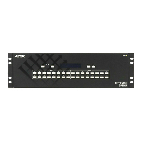
Overview
Because the Optima Distribution Matrix is available in two sizes (2 RU and 3 RU) and
various board configurations, the illustrations in this guide may differ from the model(s)
you purchased. For complete documentation for this product (including individual
board specifications), see the "Instruction Manual – Optima" on the AMX AutoPatch
CD or at www.amx.com. This product supports full Device Discovery through AMX's
AutoPatch Duet module (firmware v1.4.1 or higher is required).
General Specifications
Approvals
MTBF
Operational Temperature
Storage Temperature
Humidity
2 RU Enclosures
AC Power
100 VAC to 240 VAC single phase
(50 Hz to 60 Hz)
1.8 A @ 100 to 240 VAC (max.)
Power Consumption
260 W per enclosure (max.)
110 W per loaded enclosure (typical)
Thermal Dissipation
887 BTU/hr (max.)
375 BTU/hr, fully loaded enclosure (typical)
Dimensions
Approximately 12 in. (30.5 cm) depth
18.9 in. (48.0 cm) width with rack ears
17.4 in. (44.2 cm) width without rack ears
3.5 in. (8.9 cm) height
Weight
Approximately 10 lb. (4.54 kg)
per loaded enclosure
Installation
Rack Mounting
To rack mount an Optima enclosure:
1.
Attach the rack ears as shown left (screws provided).
2.
Install in a rack leaving a minimum of one empty rack
unit above and below (required); three empty rack
units above and below are recommended.
FIG. 1
Attach rack ears to sides of enclosure
Linking Multiple Enclosures (if applicable)
If the system has multiple enclosures, cable(s) for linking and the "Quick Start Guide,
AutoPatch – Linking Enclosures" have been provided. Link the enclosures according
to the guide.
Attaching Input and Output Cables/Wires
Before connecting all input and output cables/wires, attach only the first two inputs and
outputs, apply power (see next page), and execute a test switch (see "Completing the
Installation" on the next page). When the test switch is successful, attach the rest of
the input and output cables and wires according to the AutoPatch Connector Guide.
Follow the guide exactly; the system is configured to operate based on the guide.
Video I/O Boards – BNC
Video BNC connectors are used for standard video, wideband video, Hi-Z sync,
HV Hi-Z sync, Y/c, SD-SDI, and HD-SDI signal types.
FIG. 2
Three BNC connectors are required for a three-component signal
AutoPatch Optima Distribution Matrix
CE, UL, cUL, RoHS
92,000 hours
32° F to 110° F (0° C to 43° C)
-22° F to 158° F (-30° C to 70° C)
0 to 90% non-condensing
3 RU Enclosures
AC Power
100 VAX to 240 VAC single phase
(50 Hz to 60 Hz)
3.3 A @ 115 VAC (max.)
1.6 A @ 230 VAC (max.)
Power Consumption
260 W per enclosure (max.)
150 W per loaded enclosure (typical)
Thermal Dissipation
887 BTU/hr (max.)
512 BTU/hr, fully loaded enclosure (typical)
Dimensions
Approximately 12 in. (30.5 cm) depth
18.9 in. (48.0 cm) width with rack ears
17.4 in. (44.2 cm) width without rack ears
5.2 in. (13.2 cm) height
Weight
Approximately 12 lb. (5.44 kg)
per loaded enclosure
Note: Component signals (e.g., Y/Pb/Pr)
Y
require more than one BNC connection.
The example to the left shows three BNC
Pb
cable connectors attached for routing a
three-component signal through Output 9.
Pr
S-Video I/O Boards
S-Video boards are equipped with locking connectors, which lock on to AMX
AutoPatch S-Video cables. Standard S-Video connectors may be used, but will not
lock.
To fasten a locking S-Video connector:
1.
Hold the connector at a slight angle to the right and push in.
Or
Pull back on the connector housing while pushing in.
Connector housing
FIG. 3
Pull back on connector housing while pushing in
RGBHV/HD-15 I/O Boards
RGBHV/HD-15 boards use HD-15 connectors.
Note: 55 mA is supplied on Output Pin 9; power draw not to exceed 50 mA per port.
DVI I/O Boards
EDID Programmer software is provided for the 8x8 DVI boards to assist with in-field
programming of custom EDIDs (4x4 DVI boards do not support this software). For
information, see the "Instruction Manual – Optima."
DVI Output Pin 14 (+5 VDC out):
•
On the 4x4 DVI board, Output Pin 14 supplies 55 mA; power draw not to exceed
50 mA per port.
•
On the 8x8 DVI board, Output Pin 14 supplies 1000 mA shared total available on
Output 1 through Output 4 and 270 mA shared total available on Output 5
through Output 8. For installation information for the High-Amperage Outputs on
the 8x8 DVI board, see the "Instruction Manual – Optima."
HDMI I/O Boards
The HDMI I/O board has 8 input and 8 output HDMI connectors. It is HDMI 1.3
compatible and fully HDCP compliant. Priming the system for InstaGate
(pre-authorization of all connected source and destination devices) significantly
reduces HDCP latency (time required for authentication) in the matrix switcher for
HDCP negotiations with all connected displays (see "Instruction Manual – Optima").
* Some destination devices have a longer lag time than others between receiving a
signal and displaying that signal. Although InstaGate
switcher, it cannot reduce the lag time inherent in a device.
If needed, EDID Programmer software is provided to assist with in-field programming
of custom EDIDs (see the "Instruction Manual – Optima").
Stereo Audio I/O Boards – 5-Term
Balanced audio
FIG. 4
5-Term stereo audio wiring
Note: When using shielded twisted-pair wire, connect the shield (ground) at one end
only (recommend receiving end) to minimize low frequency noise (see FIG. 5 below).
Source and destination devices require either balanced or unbalanced connections.
More than one of the options shown in FIG. 5 can be used in the same system.
Inputs
FIG. 5
Options for source-to-Optima-to-destination 5-Term wiring
Quick Start Guide
®
reduces latency in the matrix
Note: Audio boards with 5-position
terminal block connectors can be
wired for balanced (differential) or
unbalanced (single-ended) audio.
Unbalanced audio
Outputs
®
technology*
Advertisement
Table of Contents

Related Manuals for AMX AutoPatch Optima


Summary of Contents for AMX AutoPatch Optima
-
Page 1: Quick Start Guide
Overview S-Video I/O Boards S-Video boards are equipped with locking connectors, which lock on to AMX Because the Optima Distribution Matrix is available in two sizes (2 RU and 3 RU) and AutoPatch S-Video cables. Standard S-Video connectors may be used, but will not various board configurations, the illustrations in this guide may differ from the model(s) lock. - Page 2 ©2010 AMX. All rights reserved. AMX and the AMX logo are registered trademarks of AMX. AMX reserves the right to alter specifications without notice at any time. 3000 RESEARCH DRIVE, RICHARDSON, TX 75082 • 800.222.0193 • fax 469.624.7153 • technical support 800.932.6993 • www.amx.com...
Need help?
Do you have a question about the AutoPatch Optima and is the answer not in the manual?
Questions and answers