Table of Contents
Advertisement
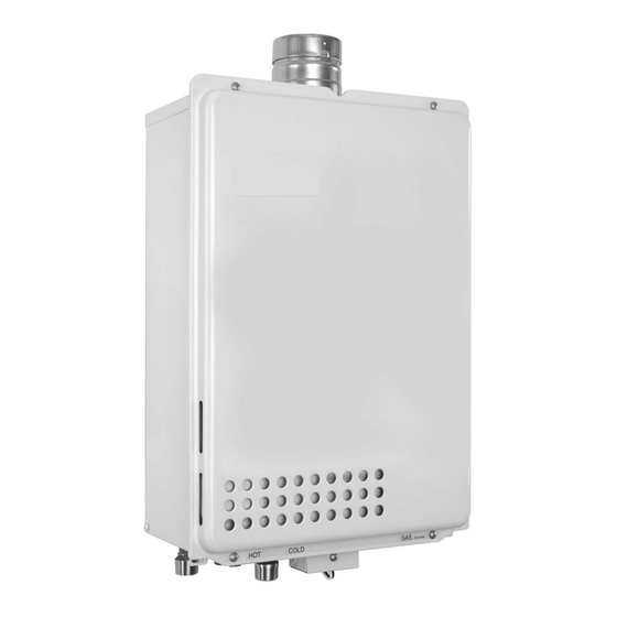
660 EF/EFO
INDOOR MODEL/OUTDOOR MODEL
Installation must conform with local codes, or in the absence of local codes, the National Fuel Gas Code,
ANSI Z223.1/NFPA 54.
When applicable, installation must conform with the Manufactured Home Construction and Safety Standard, Title 24 CFR, Part
3280 or the Canadian Standard CAN/CSA-Z240 MH Mobile Homes, Series M86. (660 EFO only)
INDOOR MODEL 660 EF- Natural Gas/Liquefied Petroleum (LP) Gas
OUTDOOR MODEL
Warning: If the information in this manual is not
followed exactly, a fire or explosion may result
causing property damage, personal injury or death.
Do not store or use gasoline or other flammable
vapors and liquids in the vicinity of this or any other
appliance.
Improper
installation,
service or maintenance can cause injury or
property damage. Refer to this manual. For
assistance or additional information consult a
qualified installer, service agency or the gas
supplier.
In the Commonwealth of Massachusetts this
product must be installed by a licensed plumber or
gas fitter.
Upon completion of the installation, these
instructions should be handed to the user of the
appliance for future reference.
SBA8517
660 EFO- Natural Gas/Liquefied Petroleum
adjustment,
alteration,
What to do if you smell gas
• Close gas valve. Open windows.
• Do not try to light any appliance.
• Do not touch any electrical switch; do not use any
phone in your building.
• Immediately call your gas supplier from a neighbor's
phone. Follow the gas supplier's instructions.
• If you cannot reach your gas supplier, call the fire
department.
• Installation and service must be performed by a
qualified installer, service agency or the gas supplier.
(LP) Gas
Advertisement
Table of Contents

Related Manuals for Bosch 660 EF


Summary of Contents for Bosch 660 EF
- Page 1 When applicable, installation must conform with the Manufactured Home Construction and Safety Standard, Title 24 CFR, Part 3280 or the Canadian Standard CAN/CSA-Z240 MH Mobile Homes, Series M86. (660 EFO only) INDOOR MODEL 660 EF- Natural Gas/Liquefied Petroleum (LP) Gas OUTDOOR MODEL...
-
Page 2: Table Of Contents
Follow- up Service Requesting Service Gas conversion Appliance details Features Specifications (Technical data) Interior components diagram Before Installation 660 EF Interior components Dimensions (660 EF) 660 EFO Interior components Dimensions (660 EFO) Protecting the environment Installation instructions Specialized tools Limited Warranty... -
Page 3: Important Safety Information
Important Safety Information Important Safety Information Attention Installers • In order to use the water heater safely, read this To prevent damage to property and injury to the user, installation manual carefully, and follow the installa- the icons shown below will be used to warn of varying tion instructions. - Page 4 Do not use this water heater if any part Fig. 2 has been under water. lmmediately call a qualified service technician to inspect Danger: [660 EF] - do not install the water heater and to replace an dam- outdoors! aged parts.
- Page 5 Warning: [660 EF only] Carbon Monoxide Poisoning Hazard. Warning: Do not install this water heater in a mo- Consult the nearest Bosch agent if the bile home, recreation vehicle or on a water heater location needs to be boat. changed.
- Page 6 Important Safety Information Warning: Caution: Contact Bosch before using with a so- Do not turn off the water heater while lar pre-heater. someone is bathing. Warning: Caution: California Proposition 65 lists chemical- Do not cover the water heater and the...
-
Page 7: Appliance Details
• Cross Recess Head Screw (660 EFO NG, 660 EFO up to 1350m (4500 ft.) above sea level. For installations at higher elevations, • Power Cord (660 EF NG, 660 EF LP). contact Bosch Thermotechnology Corp. for Instructions. Accessories (Bosch part #) •... -
Page 8: Specifications (Technical Data)
Appliance details Specifications (Technical data) Safety devices • Flame Rod Approved in US/Canada • Thermal Fuse Capacity • Lightning Protection Device (ZNR) Maximum flow rate: 5.3 GPM (20 l/min) at a 45°F • Overheat Prevention Device (25°C) rise. • Freezing Prevention Device Maximum Input •... -
Page 9: Before Installation
- Check that the rating plate indicates the correct type of gas. - Check that the gas supply line is sized for 140,000 BTU for 660 EF, 660 EFO.) Fig. 3 Ex. For LP Gas 660 EFO Warning: Check the power! The power supply required is 120VAC, at 60Hz. -
Page 10: Dimensions (660 Ef)
Appliance details Dimensions (660 EF) Fig. 4 Dimensions Dimensions (660 EFO) Fig. 5 Dimensions 6 720 644 063... -
Page 11: Installation Instructions
• Bosch Vent System is suggested for the vent system. of the pipe is not covered with snow or hit by falling If Bosch Vent is not used, a UL listed category III lumps of snow ventsystem must be used •... - Page 12 Installation instructions Horizontal Vent Termination Vertical Vent Termination Fig. 6 • Terminate at least 12" (300mm) above grade or above snow line. • Terminate at least 7' (2.1m) above a public walkway, 6' (1.8m) from the combustion air intake of any appli- ance, and 3' (0.9m) from any other building opening, gas utility meter, service regulator etc.
- Page 13 Installation instructions Clearance Requirements from Vent Terminations to Building Openings *All clearance requirements are in accordance with ANSI Z21.10.3 and the National Fuel Gas Code, ANSI Z223.1 and in Canada, in accordance with NSCNGPIC. Fig. 8 6 720 644 063...
- Page 14 Z21.10.3 and the National Fuel Gas Code, ANSI Z223.1 and in Canada, in accordance with NSCNGPIC. Vent Clearances When Heater is Installed Indoors (For 660 EF appliance) Maintain the following clearances to any opening in any building: • 4' (1.2m) below, 4' (1.2m) horizontally from, or 1' (0.3m) above any door, operable window, or gravity...
-
Page 15: Combustion Air Requirements
Installation instructions Combustion air requirements Combustion Air Supply combustion air to the units as per the National Fuel Gas Code, ANSI Z223.1 and in Canada, in accordance with NSCNGPIC. • Provide two permanent openings to allow circulation of combustion air. •... - Page 16 Installation instructions Attention residents of the Commonwealth of Massachusetts: In the Commonwealth of Massachusetts the following signage installed in accordance with the provisions of regulation went into effect on 12/30/2005: 248 CMR 5.08(2)(a)1 through 4. (a)For all side wall horizontally vented gas fueled (b)EXEMPTIONS: The following equipment is exempt equipment installed in every dwelling, building or from 248 CMR 5.08(2)(a)1 through 4:...
-
Page 17: Choosing Installation Site
Ignition failures and malfunction may gas flow will not be affected by fans or occur as a result. range hoods. Warning: [660 EF only] Caution: Carbon Monoxide Poisoning Hazard. Take care that noise and exhaust gas Do not install this water heater in amo-... -
Page 18: Installation Clearances
National Fuel Gas Code ANSIZ223.1/NFPA 54 – latest edition. In Canada, see NSCNGPIC for detailed requirements. For 660 EF Required Clearances From Heater • Maintain the following clearance from both combus- tible and non-combustible materials. 12” (300 mm) or more 4”... -
Page 19: Installation
Installation instructions For 660 EFO Required Clearances From Heater • Maintain the following clearance from both combus- tible and non-combustible materials. * ( ) indicates the distance when installing a heat insulat- ing board (non-combustible material other than metal, with thickness of 0.1" (2.5mm) or more) or "section of building effectively finished with non-combustible mate- rial."... - Page 20 Installation instructions 3.7.2 Locating Scew Holes 3.7.5 Installations at Elevations Above 2,000' (610m) Caution: • If this water heater is being installed at an elevation B When installing with bare hands, take of 2,000' (610m) or higher, disconnect the connec- caution to not inflict injury.
-
Page 21: Gas Piping
• Gas flex lines are not recommended unless they are rated for 140,000 btuh (660 EF/660 EFO). • Install a gas shutoff valve on the supply line. • Use only approved gas piping materials. - Page 22 Installation instructions Measuring Gas Pressure • In order to check the gas supply pressure to the unit, a tap is provided on the gas inlet. Remove the hex head philips screw from the tap, and connect a manometer using a silicon tube. •...
- Page 23 Installation instructions Gas Line Sizing For a BOSCH Gas Water Heater 6 720 644 063...
-
Page 24: Water Piping
Heating Boilers). This pressure relief valve must be capable of an hourly Btu rated temperature steam dis- charge of 140,000 Btuh for 660 EF-(O)). Multiple valves may be used. The pressure relief capacity must not exceed 150 psi. No valve shall be placed between the relief valve and the water heater. -
Page 25: 3.10 Water Treatment
Required Total Hardness 100 mg/L (6 gpg) or less Table 5 Aluminum 0.05 to 0.2 mg/L or less Install Bosch Isolation Valves to allow for flushing. Chloride 0.05 to 0.2 mg/L or less Copper 1 mg/L or less Iron 0.3 mg/L or less Manganese 0.05 mg/L or less... - Page 26 Water Softener Softener (> 239 mg/L) Required Table 6 Install Bosch Isolation Valves to allow for flushing. Flushing is required if a water softener is not installed. Flushing is required if a water softener is not installed. 6 720 644 063...
-
Page 27: 3.11 Plumbing Applications
Installation instructions 3.11 Plumbing Applications Refer to section 11 for Limited Warranty. Fig. 25 Fig. 26 6 720 644 063... -
Page 28: Electrical Wiring
Electrical Wiring Electrical Wiring Electrical wiring Warning: Tie the redundant power cord outside Consult a qualified electrician for the the water heater. Putting the redundant electrical work. length of cord inside the water heater may cause electrical interference and faulty operation. Warning: Do not connect electrical power to the unit until all electrical Ground... -
Page 29: Remote Controller
130°F (55°C) ,140°F, 150°F, 160°F (60°C, 65°C, 70°) Cusing the UP and DOWN setting buttons. • The 660 EF can be programmed so that it will default 10. To put the water heater back into operation, press to one of three temperatures 140°F, 130°F, 120°F the ON/OFF button on the remote controller. -
Page 30: Remote Controller Installation Guide
Electrical Wiring • Be sure to hand tighten when screwing to the termi- Included Parts List nal block. Power tools may cause damage to the ter- Part Name Quantity minal block. Remote controller cord Remote Controller • For extensions, a 26' (7.8m) cord can be purchased Wall Packing (Part # BRC26CORD) or use 18AWG wire. - Page 31 Electrical Wiring 3. Insert the wall pipe containing the remote controller wires through the hole. 4. Slide the junction box packing and the junction box over the remote controller wires and wall pipe protrud- ing from the outside wall. Fig. 31 3.
- Page 32 Electrical Wiring Fig. 36 Tie the redundant length of the remote controller cord outside the junction box. 7. Close the junction box. 6 720 644 063...
-
Page 33: Operation Instructions
Operation instructions Operation instructions 2. Turn off all electrical power to the unit. The installer should test operate the unit, 3. Do not attempt to light the burner by hand. explain to the customer how to use the unit, and give the owner this manual be- 4. -
Page 34: How To Use
If you want to the temperature to be changed to 130 °F (55 °C) or 140 °F (60 °C), contact the installer or Bosch. Danger: To prevent scalding Hot Water Heater temperatures over 125 °F (52 °C) can cause severe burns instantly or death from scalding. -
Page 35: How To Use (Using The Remote Controller)
Operation instructions How to Use (Using the remote controller) Setting and Using the Water Heater The illustration below shows the remote controller display. What is actually dis- played depends on how the water heater is set. CANADA REMOTE CONTROL USA REMOTE CONTROL (PART N# BRC01CA) (PART N# BRC01US) Fig. - Page 36 Operation instructions The alarm will sound when the set level has been Danger: To prevent scalding reached. Stop the water. Do not allow anyone to change the wa- ter temperature while hot water is run- An alarm will sound for ten seconds when ning.
-
Page 37: Maintenance And Service
Maintenance and service Maintenance and service • For abnormal sounds during operation. Periodically check the following to ensure • For abnormalities in external appearance, discolora- proper operation of the water heater. tion or flaws. • For proper operation of pressure relief valve. •... -
Page 38: Preventing Damage From Freezing
• Isolation valves may be purchased as an accessory (outdoor installation). This method can protect not only from Bosch. They allow for full diagnostic testing and to the heater, but also to the water supply, water piping easy flushing of the system and mixing valves. - Page 39 Maintenance and service 4. When the water is flowing again, check for water leaks from the equipment and piping before using. If the heater or the piping is frozen, do not use the heater or it may get damaged. If the water heater will not be used for a long period of time, drain the water Drain the water as follows: Caution:...
-
Page 40: Troubleshooting
Troubleshooting Troubleshooting Initial Operation Unit does not attempt to ignite when Check for reversed plumbing or crossed pipes. water is running. Check the water drain valve filter. Unit attempts to ignite but fails. Reset unit and try again. There may be air in the gas line. Have a professional check the gas supply pressure. -
Page 41: Amount Of Hot Water
When hot water is demanded at other fixtures, the amount available may fixture is not constant. be reduced. The maximum flow available from the 660 EF, 660 EFO is 5.3 GPM (20.0L/min.) at a 45°F ( 25°C) temperature rise. Pressure fluctuations and other plumbing conditions can cause the tem- perature and pressure at a fixture to be unstable, but it should stabilize after a short time. -
Page 42: Remote Controller
Troubleshooting Remote Controller The light on the power button does not come Has there been a power failure? Is the power connected properly? The water temperature changes after a The temperature setting and the flow meter alarm setting may power failure or when the power is discon- both need to be reset after a power outage. -
Page 43: Others
Troubleshooting Others The heater stops burning during operation. Are the gas and water supply valves fully open? Is the water supply cut off? Is the hot water fixture sufficiently open? Is the gas being cut off by the gas meter? (Can other gas devices such as stoves be used?) (For LP) Is there enough gas in the tank? (Can other gas devices such as stoves be used?) -
Page 44: Check For An Error Code (Using The Remote Controller)
If the flashing number doesn't return the problem is solved. Abnormal combustion, low gas supply pres- Have a professional check the gas supply sure. pressure. Contact the nearest Bosch agent. Abnormal combustion. Contact the nearest Bosch agent. Table 15 Contact Bosch Thermotechnology if: •... -
Page 45: Follow- Up Service
Requesting Service your water heater model on the table First follow the instructions in the troubleshooting sec- provided below. tion. If the error is not corrected, contact Bosch Ther- motechnology Corp. at 1-866-330-2730. Conversion Conversion We will need to know:... -
Page 46: Interior Components Diagram
Interior components diagram Interior components diagram 660 EF Interior components Fig. 45 Components 6 720 644 063... -
Page 47: Efo Interior Components
Interior components diagram 660 EFO Interior components Fig. 46 Components 6 720 644 063... -
Page 48: Protecting The Environment
Protecting the environment Protecting the environment Packing The packing box may be fully recycled as confirmed by the recycling symbol Components Many parts in the heater can be fully recycled in the end of the product life. Contact your city authorities for information about the disposal of recyclable products. -
Page 49: Limited Warranty
Bosch Thermotechnology Corp. shall be in lieu of any • 4. to failure of the heat exchanger resulting from the and all other warranties, express or implied, including... - Page 50 Limited Warranty 6 720 644 063...
- Page 51 Limited Warranty 6 720 644 063...
- Page 52 Installation manual should be left with the owner after the installation is tested and completed Replacement Parts available from: BOSCH THERMOTECHNOLOGY CORP. Bosch Termotecnologia SA 50 Wentworth Avenue Estrada de Cacia Londonderry, NH 03053 USA 3801 - 856 Aveiro - PORTUGAL Tel. 866-330-2730 www.boschpro.com © 2010 Bosch Thermotechnology Corp., Londonderry, NH...
Need help?
Do you have a question about the 660 EF and is the answer not in the manual?
Questions and answers