Table of Contents
Advertisement
Gas water heaters
WT 11 AM1 E
Installation and Users Instructions
Read installation manual prior to installation of this unit!
Read user manual before putting this unit in operation!
Observe the warnings in the manuals!
The installation room must fulfill the ventilation requirements!
Installation by an authorised person only!
Advertisement
Table of Contents

Related Manuals for Bosch WT 11 AM1 E


Summary of Contents for Bosch WT 11 AM1 E
- Page 1 Gas water heaters WT 11 AM1 E Installation and Users Instructions Read installation manual prior to installation of this unit! Read user manual before putting this unit in operation! Observe the warnings in the manuals! The installation room must fulfill the ventilation requirements!
-
Page 2: Table Of Contents
2 | Table of contents Table of contents Key to symbols and safety instructions ..3 Electrical connection ..... . . 18 Key to symbols . -
Page 3: Key To Symbols And Safety Instructions
Key to symbols and safety instructions | 3 If there is a smell of burnt gases: Key to symbols and safety instructions ▶ Disconnect the appliance. ▶ Open doors and windows. Key to symbols ▶ Inform an installation company. Warnings Fitting, modifications ▶... -
Page 4: Appliance Specifications
4 | Appliance specifications appliance and understand the resulting Appendices • Gas water heater dangers. Children must not play with the • Fitting elements appliance. Cleaning and user maintenance • Set of flow-restrictor plates must not be performed by children without •... -
Page 5: Dimensions
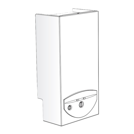
Appliance specifications | 5 Dimensions Ø 6720607298-04.2Av Fig. 1 [1] Front cover [2] Mirror [3] On/off switch [4] Fan [5] Heat exchanger [6] Burner [7] Control box [8] Temperature selector [9] Fixing bracket WT11 Table 4 Dimensions 6 720 607 800 (2016/02) -
Page 6: Electrical Layout
6 | Appliance specifications Electrical layout Operational instructions Hot water Open the gas and water valves and ensure that all joints are hermetic. Place the main switch (Fig. 3, [3]) in the operating position (chapter 3.2), so that the appliance is quickly ready for use. When a hot tap is opened, the water flow sensor should be in (Fig. -
Page 7: Technical Data
Appliance specifications | 7 Technical data Technical characteristics Symbols Units WT11 Power Usable power 19,3 Minimum usable power Pmin Regulatory field 7 - 19,3 Nominal power 21,8 Minimum nominal power Qmin Gas data Inlet pressure G.P.L. (Butane/Propane) G30/G31 mbar 28-30/37 Consumption* G.P.L. -
Page 8: 2.10 Product Data On Energy Consumption
The following product data complies with the requirements of EU Regulations 811/2013, 812/2013, 813/2013 and 814/2013 as supplement to the Directive 2010/30/EU. Product data Symbol Unit 7701411040 Product type – – WT 11 AM1 E 31 Emissions of nitrogen oxides mg/kWh Sound power level, indoors dB(A) Declared load profile – – Other load profiles –... -
Page 9: Use
Use | 9 Fig. 3 Connect and disconnect the appliance [1] Reset button [2] Temperature selector Connect [3] Main switch ▶ Turn the main switch to position I. [4] Burner state key The panel shows the temperature to which the water will be Before operating the appliance heated. -
Page 10: Regulation Of Water Temperature
10 | Use Regulation of water temperature Purge appliance If there is a risk of freezing, proceed as follows: The temperature value on the regulator ▶ Loosen the purge screw (Fig. 6) located on the water inlet corresponds to the emission temperature. pipe. -
Page 11: Flue Accessories
Flue accessories | 11 Type Description TTNR Flue accessories AZ388 Horizontal set 7 716 050 063 Flue Accessories Flue pipe 350 mm 7 736 995 059 Flue pipes have an internal diameter of 60 mm and external Flue pipe 750 mm 7 736 995 063 diameter of 100 mm. - Page 12 12 | Flue accessories Fig. 8 Restrictor plate ▶ Loosen accessory fixing screws (Fig. 11, [1]). ▶ Place restrictor plate (Fig. 11, [2]) between the accessory and the appliance. ▶ Reassemble the accessory in the appliance using the 4 screws (Fig. 11, [1]). Security distance, flat roof inflammable material inflammable material...
-
Page 13: 4.1.3 Horizontal Flue
Flue accessories | 13 4.1.3 Horizontal flue Fig. 10 Recommended clearance (mm) [1] AZ 388 WT11 Table 10 4.1.4 Fitting the restrictor plate Depending on flue exhaust and installations conditions, a restrictor plate may need to be fitted (Fig. 11) under the accessory (table 11 and 12). -
Page 14: Regulation
14 | Regulation Flue configuration C - horizontal, with accessory AZ388 and 7736995083 90° [mm] [mm] WT.11 1500 1 x 90° 4000 Ø 78 1500 - 2500 Ø 78 2500 - 4000 Ø 78 2000 2 x 90° 2000 Ø... -
Page 15: Installation
Installation | 15 Solar installations Installation DANGER: Explosion ▶ Always turn off the gas cock before carrying out any work on components which carry gas. Installation, electrical connection, gas installation, connection of inlet and exhaust pipes and initial startup must be realized exclusively by authorized personnel. -
Page 16: Minimum Distances
16 | Installation ▶ The appliance must not be installed in sites where the Installation of support bar ambient temperature is susceptible to drop below 0 °C. Before installing the support bar, ensure that Where there is a risk of freezing, disconnect and empty the the water/gas/exhaust connections are appliance (Fig. -
Page 17: Water Connection
Installation | 17 CAUTION: ▶ Never rest the heater on the gas or water connections. For ease of installation it is recommended that the water be connected followed by the rest of the connections. Water connection ▶ Mark the hot and cold water pipes in order to avoid confusion. -
Page 18: Electrical Connection
18 | Electrical connection Electrical connection DANGER: Electrical discharge! ▶ Before working on the electrical installation, always disconnect the electrical current. The appliance is provided with a labelled feed cable. All regulation, verification and safety mechanisms have been rigorously tested in the factory and are ready for use. CAUTION: Storms 6720680323-01.1Av ▶... -
Page 19: Pressure Regulation
Gas regulation | 19 ▶ Connect the U-tube manometer to the burner pressure The selection of the fastest burner pressure measuring point. process is recommended. Pressure regulation Access to the adjuster screw ▶ Remove the appliance front cover (see page 16). ▶... -
Page 20: Changing Gas Type
Prior to commencing maintenance work: ▶ Isolate the appliance from the power supply. ▶ Close the water shut-off valve. ▶ Close the gas tap. ▶ Your appliance must only be serviced by a BOSCH Technical Assistance delegate. 6 720 607 800 (2016/02) -
Page 21: Periodic Maintenance Tasks
Maintenance | 21 ▶ Use only authentic spares and accessories. ▶ Remove the fuses from the box (Fig. 22, [1]) and remove cap. ▶ Order spares from the list supplied with the appliance. ▶ Substitute dismantled joints and o-rings with new ones. ▶... -
Page 22: Problems
22 | Problems Problems Note: Installation, maintenance and repairs must be carried out only by qualified technicians. In the table above solutions to possible problems are described (solutions followed by * must only be carried out by qualified technicians). Problem Cause Solution Appliance does not ignite and control... -
Page 23: Environmental Protection
Environmental protection | 23 Environmental protection Environmental protection is one of the fundamental company policies of the Bosch Group. Safety, environmental compatibility and economy are of equal importance in the development and manufacture of our products. These values improve safety and the way our customers feel...
Need help?
Do you have a question about the WT 11 AM1 E and is the answer not in the manual?
Questions and answers