Table of Contents
Advertisement
Quick Links
U S E R M A N U A L
Series X - Maritime Multi Display (MMD) Models
HD 12T21 MMD-xxx-Fxxx - 12.1 inch Maritime Multi Display
HD 15T21 MMD-xxx-Fxxx - 15.0 inch Maritime Multi Display
HD 17T21 MMD-xxx-Fxxx - 17.0 inch Maritime Multi Display
HD 19T21 MMD-xxx-Fxxx - 19.0 inch Maritime Multi Display
HD 24T21 MMD-xxx-Fxxx - 24.0 inch Maritime Multi Display
HD 26T21 MMD-xxx-Fxxx - 25.54 inch Maritime Multi Display
Please visit www.hatteland-display.com for the latest electronic version of this manual.
Hatteland Display AS, Åmsosen, N-5578 Nedre Vats, Norway
Tel: (+47) 4814 2200 - mail@hatteland-display.com - www.hatteland-display.com
User Manual MMD Series X
Updated: 10 Jan 2013
Doc Id: INB100519-1 (Rev 5)
Created: 363
Approved: 6542
Advertisement
Table of Contents

Related Manuals for Hatteland HD 12T21


Summary of Contents for Hatteland HD 12T21
- Page 1 Updated: 10 Jan 2013 Doc Id: INB100519-1 (Rev 5) Created: 363 Approved: 6542 Please visit www.hatteland-display.com for the latest electronic version of this manual. Hatteland Display AS, Åmsosen, N-5578 Nedre Vats, Norway Tel: (+47) 4814 2200 - mail@hatteland-display.com - www.hatteland-display.com...
- Page 2 Copyright © 2013 Hatteland Display AS Aamsosen, N-5578 Nedre Vats, Norway. All rights are reserved by Hatteland Display AS. This information may not, in whole or in part, be copied, photocopied, reproduced, translated or reduced to any electronic medium or machine- readable form without the prior written consent of Hatteland Display AS.
-
Page 3: Table Of Contents
Contents Contents ..................3 Contents of package ..................6 General .................... 7 About this manual ..................8 About Hatteland Display ................8 www.hatteland-display.com ................8 Contact Information ..................8 Maritime Multi Display (MMD) - Introduction ..........9 Product Labeling ..................10 Labels and Locations ..............10 Typenumber Structure (example) ..........10 Warranty Label ................10... - Page 4 Specifications - HD 24T21 MMD-xxx-Fxxx ..........62 Specifications - HD 26T21 MMD-xxx-Fxxx ..........63 Technical Drawings ..............65 Technical Drawings - HD 12T21 MMD-xxx-Fxxx ........66 Technical Drawings - HD 15T21 MMD-xxx-Fxxx ........67 Technical Drawings - HD 17T21 MMD-xxx-Fxxx ........68 Technical Drawings - HD 19T21 MMD-xxx-Fxxx ........69 Technical Drawings - HD 24T21 MMD-xxx-Fxxx ........70...
- Page 5 Contents Appendixes ................... 79 Pinout Assignments .................80 Basic Trouble-shooting ................84 Declaration of Conformity ................85 Return Of Goods Information ..............86 Terms .......................87 Pixel Defect Policy ...................89 Notes ......................90 Revision History ..................92 IND100130-43...
-
Page 6: Contents Of Package
Contents of package Item Description Illustration 1 pcs of Standard DVI Signal Cable. DVI-D 18+1P Male to DVI-D 18+1P Male Single Link - Length 2.0m HA-SDM-2M 1 pcs of Standard VGA Signal Cable. DSUB 15P Male to DSUB 15P Male - Length 2.0m HA-VGA-2M-32 1 pcs of power cable European Type F “Schuko”... -
Page 7: General
General... -
Page 8: About This Manual
About Hatteland Display Hatteland Display is the leading technology provider of specialized display and computer products, delivering high quality, unique and customized solutions to the international maritime, naval and industrial markets. -
Page 9: Maritime Multi Display (Mmd) - Introduction
Maritime Multi Display (MMD) - Introduction As a leading manufacturer of display and computer hardware for the maritime segment, Hatteland Display continuously gauges and responds to market needs. Our commitment to develop specialized products for a multitude of onboard ship systems continues, and with that the introduction now of a brand new product range called, Series X. -
Page 10: Product Labeling
Series X Displays - Typenumber Overview IND100780-3 - Rev 06 - 02 Mar 2012 This document explains the type number structure for the Product Type Hatteland Display Series X Maritime Multi Display product range. - Example standard typenumber: Manufacturer & Country Manufactured Date yyyymmdd HD 19T21 MMD-MA1-FAGA Input Voltages &... -
Page 11: Installation
Installation... -
Page 12: First Things First
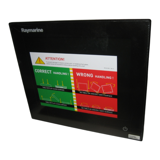
General Installation Recommendations First Things First! ATTENTION! IND100148-5 - Rev 02 To prevent damage to chassis and glass, please review the illustrations below before handling units. WRONG CORRECT HANDLING ! HANDLING ! Do not stress the corners, nor place Place horizontally on a smooth and clean surface it on a coarse and/or dirty surface Do not stress the corners, nor place Place horizontally on a smooth and clean surface... -
Page 13: General Mounting Instructions
9. The classification is only valid for approved mounting brackets provided by Hatteland Display. The unit shall be mounted stand-alone without any devices or loose parts placed at or nearby the unit. Any other type of mounting might require test and re-classification. -
Page 14: Ergonomics
General Installation Recommendations Ergonomics 1. The front surface of the display glass has an anti-reflective (AR) coating which can be scratched and damaged with improper cleaning. It is recommended to use only 90+% pure Isopropyl alcohol (Isopropanol) and a soft fabric cloth for this first cleaning. -
Page 15: Maximum Cable Length
General Installation Recommendations Maximum Cable Length Any cable should generally be kept as short as possible to provide a high quality input/output. The maximum signal cable length will depend on the signal resolution and frequency, but also on the quality of the signal output from the computer/radar. -
Page 16: Panel / Console Mounting Key Hole Bracket Kit For 12",15",17",19
Installation Procedures Panel / Console Mounting Key Hole Bracket Kit for 12”,15”,17”,19” You need: Allen Wrench tool (3mm), 4 pcs of HD CMB SX1-A1 kit (included in delivery). Procedure suitable for: Display and Panel Computers Series X range. Attention: A suitable pre-cut panel cutout should be made prior to mounting. Do not force the unit into the panel cutout as it might break the outer glass or scratch the chassis on the unit. -
Page 17: Panel Cutout / Console Mounting Bracket Kit For 24",26
Installation Procedures Panel Cutout / Console Mounting Bracket Kit for 24”,26” You need: Pozidriv tool, 1 pcs of HD CMB SX1-B1 kit (included in delivery). Procedure suitable for: Display and Panel Computers Series X range. 24 inch used as illustration below, but same procedure also valid for 26 inch models. -
Page 18: Mounting Bracket For Table / Desktop Installation - 12",15",17",19
Attention: A suitable pre-drilled location and knowledge of measurements for both main unit and brackets/tilting functionality should be prepared and checked prior to mounting. Please disconnect ALL cables before proceeding. Please review User Manual or visit www.hatteland-display.com for Technical Drawings regarding measurements for both main unit and Mounting Brackets. - Page 19 Installation Procedures Note: Some units may have Single Key Hole, whilst others have Double Key Hole. This is due to slight variation in initial production vs Mass Production throughout 2012. During early 2013, all units will have Double Key Hole. 2012 2012 / 2013 5: Ensure that both Key Hole Plugs slide into the Key Holes and goes to the bottom position (FIG1 and FIG2).
-
Page 20: Mounting Bracket For Table / Desktop Installation - 24",26
Attention: A suitable pre-drilled location and knowledge of measurements for both main unit and brackets/tilting functionality should be prepared and checked prior to mounting. Please disconnect ALL cables before proceeding. Please review User Manual or visit www.hatteland-display.com for Technical Drawings regarding measurements for both main unit and Mounting Brackets. -
Page 21: Physical Connections
Physical Connections Connection area of unit (illustration) 3 x BNC, Composite Video IN USB Touch 2 x DVI-D In RS-232 COM VGA/RGB Out Power Input AC RJ45 Network RS-422/RS-485 COM 2 x VGA/RGB In Potmeter Port Power Input DC Grounding Screw Note: 19 inch unit used as example above, please review specifications for your actual model. -
Page 22: Ind100130
Physical Connections DVI-D IN: Connect your DVI cable to any of the two DVI-D 18+1P, Single Link Connector (female). Secure your DVI cable to the hex spacers provided on the unit and make sure you do not bend any of the pins inside the connector. Connect the other end of the cable to the DVI connector on your equipment and secure it. -
Page 23: Power Input
Physical Connections POWER INPUT: The internal AC power module supports both 115VAC/60Hz and 230VAC/50Hz power input. Please check specifications for your unit. POWER INPUT: Connect your DC power cable to the Phoenix 2pin 1927564 MSTB 2,5/2-GF-5,08 THT connector. The internal DC power module supports 24VDC. - Page 24 This page left intentionally blank...
-
Page 25: Operation
Operation... -
Page 26: User Controls
User Controls USER CONTROLS OVERVIEW The units are designed by using Glass Display Control™ (GDC) touch technology to allow interactivity adjusting brilliance (brightness) and control power on / off with the use of illuminated symbols. Note that these symbols are only visible (backlight illuminated) when suitable power is connected. - Page 27 Used to sense level of ambient light in the surrounding environment. The sensor data can be read by suitable software through the Hatteland Display SCOM functionality of the unit and thus can be used to control brightness remotely. Note: This sensor is not visible for the eye or has any illumination behind to indicate it’s position. Further, by touching or covering this area will naturally make the sensor data inaccurate.
-
Page 28: On Screen Display (Osd) Menu Introduction
OSD Menu Overview On Screen Display (OSD) Menu Introduction The OSD menu consists of main menus and submenus which is very easy to navigate through. All functions are explained in-depth later in this user manual. You should prior to using the OSD menu and functions, be sure to familiarize yourself with how to physically access the menu, how to navigate up/down/left/right, how to modify values, exiting menus and more. -
Page 29: Osd Simplified And Full Menu Modes (Examples)
OSD Menu Overview OSD Simplified and Full Menu modes (examples) You may encounter two different menu size setups based on factory default or by customized preset configuration. The Simplified Menu mode offers easy and clear access to most commonly used functions. The Full Menu mode offers a more advanced menu with technical information and is suited for more technical minded users. -
Page 30: Osd Menu Structure
OSD Menu Overview OSD Menu Structure In this table all functions within menus and their submenus are shown. Functions that begins with an asterix (*) and in bold/red font color style indicates this function/menu is only available during “Full” menu mode or during Video CVBS fullscreen. -
Page 31: Color Mode Settings
OSD Menu Overview Color Mode Settings (page 37) Level 1 (Main Menu) Level 2 Level 3 Level 4 Level 5 Color Mode Settings > < Exit Color Temperature > 9300K, 8000K, 6500K > (Automatic Action) User > < Exit Red > (Slider Bar) Green >... -
Page 32: Osd Settings
OSD Menu Overview OSD Settings (page 40-43) Level 1 (Main Menu) Level 2 Level 3 Level 4 Level 5 OSD Settings > < Exit OSD Position > < Exit OSD H Position > (Slider Bar) OSD V Position > (Slider Bar) Language >... -
Page 33: Management Settings
OSD Menu Overview Management Settings (page 44-49) Level 1 (Main Menu) Level 2 Level 3 Level 4 Level 5 Management Settings > < Exit * Graphic Scaling > < Exit Graphic Scaling > Full Screen, Fill to Aspect Ratio, 1:1 Zoom >... -
Page 34: On Screen Display (Osd) Menu Functions
OSD Menu Functions On Screen Display (OSD) Menu Functions The following section covers all possible settings that the user can (in a certain mode) encounter or needs to adjust via easy understandable menus, text and navigation. For simpler reading the menu choice “Exit” has been left out of description in this chapter intentionally. -
Page 35: Osd Menu Functions
OSD Menu Functions Input Source Settings - Rename Source |---2--- By factory default, every signal source input are named based on it’s signal property as described in the previous functions, but with the rename source function you can rename these into more understandable descriptions like;... - Page 36 OSD Menu Functions Image Settings Lets you configure various visual preferences for any signal. The contents of these submenu are listed below. Image Settings - Auto Position |---2--- Will automatically fit the current displayed full screen signal and center it based on the active area of the TFT display.
- Page 37 OSD Menu Functions Image Settings - Hue *Available in “Full Mode” only + Video Fullscreen |---2--- Allows to adjust/shift the main color properties of all Red, Green, Blue and Yellow (unique hues) values. This can be useful for certain Composite Video sources (no effect on DVI/VGA signals) whose output may have shifted or seems to be “out of phase”, where for instance blue seems more dominant than green, red and yellow-ish colors.
- Page 38 OSD Menu Functions Image Settings - Display - Clock |--------3-------- Adjust the horizontal frequency (clock) of the analog signal to improve visibility of the entire image. When it is adjusted, you will notice that the image will appear to be stretched and might in some situations start to flicker/scroll, at which point you must reverse the last adjustment to stop it from flickering/scrolling anymore.
- Page 39 OSD Menu Functions Image Settings - Video Setup *Available when Video Fullscreen only |---2--- Provides submenus where the following settings for Composite video signals are available: Image Settings - Video Setup - Main MADI mode |--------3-------- Motion Adaptive De-Interlacing. Motion adaptive de-interlacing is a pixel-based two-phase process.
- Page 40 OSD Menu Functions Image Settings - Video Setup - Noise Reduction - MPEG NR Mode |-------------4------------- MPEG NR (the generic coding of moving pictures and associated audio information) can be set to either “ON” or “OFF”. This function will try to reduce noise as result from compressed/formatted MPEG video streams.
- Page 41 OSD Menu Functions Color Mode Settings Lets you adjust the color temperature (Kelvin degrees) of the image. This applies to the Main Source signal. Window overlays (PIP/PBP) and the OSD Menu overlay will be unaffected. Lower values make the image appear warmer, while higher values will make it appear cooler.
- Page 42 OSD Menu Functions Multi-PIP Settings Lets you adjust how the Picture-in-Picture (PIP) or Picture-by-Picture (PBP) display mode is set up. The default position of the rectangle is set to upper left corner of the Active Display area. Note that this requires a valid incoming signal to be present in either the VGA or CVBS inputs.
- Page 43 OSD Menu Functions Multi-PIP Settings - PIP Position |--------3-------- When PIP Child mode is active, the size and position of the frame displaying the Secondary Source can be adjusted by means of submenus for size and position respectively below. Settings as follows: “PIP H-Position”...
- Page 44 OSD Menu Functions OSD Settings Allows you to customize the visual appearance of the On Screen Display (OSD) menu, such as; position, transparency, time-out, assign hot keys, define access modes and save, load and recall favourite settings and more. The contents of these submenus are listed below. OSD Settings - OSD Position |---2---...
- Page 45 OSD Menu Functions OSD Settings - Presets - Save |--------3-------- Allows to save current state of all function and values to user defined presets. The contents of the submenu is listed below. Settings as follows: “User 1” = Save all OSD settings to User 1 slot. “User 2”...
- Page 46 OSD Menu Functions OSD Settings - OSD Mode |---2--- Configuring the OSD Mode to show as simplified/most common functions or advanced (full) setup. Settings as follows: “Simplified” = A few functions is not visible/available in this state. For most uses this is the preferred setting and are safe for the display functionality and continuous trusted operation on the unit.
- Page 47 OSD Menu Functions OSD Settings - OSD Key Outdoor |---2--- To prevent accidental activation of Glass Display Control™ (GDC) touch functions, you can add an extra layer of security on how “sensitve” the touch detection operates. This applies for “MENU”, “(-) Brilliance (+)”...
- Page 48 OSD Menu Functions Management Settings Allows you to adjust overall settings for interaction/communication for the unit, such as scaling, zoom, timing of signals, adjust voltages for LED (which illuminate the front glass symbols), sensitivity for the touch control, VGA filter and Serial/Ethernet communication and more. The contents of these submenus are listed below.
- Page 49 OSD Menu Functions Management Settings - Graphic Scaling - Horizont Stretch |--------3-------- All stretching will performed from center of active display area and outwards in one direction. Settings as follows: “Horizont Stretch” = Zoom/stretch current full screen signal in Horizontal direction only (left and right).
- Page 50 OSD Menu Functions Management Settings - Unknown Timing Search *Available in “Full Mode” only |---2--- Use this if you are unable to find or detect the incoming full screen signal automatically (applies for Analog VGA and CVBS video signals only. A PIP or PBP configured signal is not supported). It may be a customized signal regarding resolution and refresh frequency.
- Page 51 “Reset Factory Default” (or “Load User Default”+Slot Number, if available and previously stored by using “Save User Default”+Slot Number) commands if you are unable to navigate the OSD menu. Please review the appropriate Technical User Manual located here: http://www.hatteland-display.com/pdflink/inb100018-4.php User Controls IND100064-38...
- Page 52 OSD Menu Functions Management Settings - Filter *Available in “Full Mode” only |---2--- Filter (applies for VGA1 signal input only) is a Signal Noise Reduction technique to enhance a possible weak or bad RGB/VGA signal. It will remove certain types of noise patterns typically apparent in close proximity of other electronic equipment with less or lack of proper shielding to prevent interference.
- Page 53 ● Note: Default mode is “RS232” protocol. A more detailed description of the SCOM (Serial/Ethernet Communication) can be found here: http://www.hatteland-display.com/pdflink/inb100018-4.php Review also the “Pinout Assignments” chapter in this manual for additional help during preperation and/or installation of external equipment intended to communicate with.
- Page 54 OSD Menu Functions Service Will show various technical and unit related information, such as; Firmware versions, Elapsed Time, Internal Temperature, Fault Status and activation for the internal Test Pattern image useful for trouble- shooting. Some of these functions are static information while others are accessible. Whenever you are in contact with helpdesk or service personnel, they might require you to read back some of these values in order to precisely pinpoint any problem/question you should have with the unit or its functionality.
- Page 55 OSD Menu Functions Service - Test Pattern |---2--- Will show the internal test pattern with greyscales, colors and raster patterned boxes to check for deviations in the TFT panel/display controller behaviour. It is independent of any current resolution or specifications found in the signal inputs. The test pattern is generated internally in the display controller and is sent 1:1 directly to the TFT panel.
- Page 56 This page left intentionally blank...
-
Page 57: Specifications
Specifications... -
Page 58: Specifications - Hd 12T21 Mmd-Xxx-Fxxx
= 1 x Table Mount Bracket. EN60945 Tested* • 115&230VAC - 50/60Hz : HD 12T21 MMD-Cxx-Fxxx model • 12-24 VDC (14VDC nominal) : HD 12T21 MMD-Fxx-Fxxx model Please see user manual/datasheet for more information Power Consumption: Factory Options: • Operating Standard : 21W (typ) - 60W (max) •... -
Page 59: Specifications - Hd 15T21 Mmd-Xxx-Fxxx
Specifications - HD 15T21 MMD-xxx-Fxxx SPECIFICATIONS Note: All specifi cations are subject to change without prior notice! Please visit www.hatteland-display.com for the latest electronic version. All specifications are subject to change without prior notice! TFT Technology: Physical Considerations: • High Quality TFT with LED Backlight •... -
Page 60: Specifications - Hd 17T21 Mmd-Xxx-Fxxx
Specifications - HD 17T21 MMD-xxx-Fxxx SPECIFICATIONS Note: All specifi cations are subject to change without prior notice! Please visit www.hatteland-display.com for the latest electronic version. All specifications are subject to change without prior notice! TFT Technology: Physical Considerations: • High Quality TFT with LED Backlight •... -
Page 61: Specifications - Hd 19T21 Mmd-Xxx-Fxxx
Specifications - HD 19T21 MMD-xxx-Fxxx SPECIFICATIONS Note: All specifi cations are subject to change without prior notice! Please visit www.hatteland-display.com for the latest electronic version. All specifications are subject to change without prior notice! TFT Technology: Physical Considerations: • High Quality TFT with LED Backlight •... -
Page 62: Specifications - Hd 24T21 Mmd-Xxx-Fxxx
Specifications - HD 24T21 MMD-xxx-Fxxx SPECIFICATIONS Note: All specifi cations are subject to change without prior notice! Please visit www.hatteland-display.com for the latest electronic version. All specifications are subject to change without prior notice! TFT Technology: Physical Considerations: • High Quality TFT with LED Backlight •... -
Page 63: Specifications - Hd 26T21 Mmd-Xxx-Fxxx
Specifications - HD 26T21 MMD-xxx-Fxxx SPECIFICATIONS Note: All specifi cations are subject to change without prior notice! Please visit www.hatteland-display.com for the latest electronic version. All specifications are subject to change without prior notice! TFT Technology: Physical Considerations: • High Quality TFT with CCFL Backlight •... - Page 64 This page left intentionally blank...
-
Page 65: Technical Drawings
Technical Drawings... -
Page 66: Technical Drawings - Hd 12T21 Mmd-Xxx-Fxxx
Technical Drawings - HD 12T21 MMD-xxx-Fxxx TBD, DRAWINGS PENDING IND100132-218... -
Page 67: Technical Drawings - Hd 15T21 Mmd-Xxx-Fxxx
Technical Drawings - HD 15T21 MMD-xxx-Fxxx IND100132-219... -
Page 68: Technical Drawings - Hd 17T21 Mmd-Xxx-Fxxx
Technical Drawings - HD 17T21 MMD-xxx-Fxxx IND100132-220... -
Page 69: Technical Drawings - Hd 19T21 Mmd-Xxx-Fxxx
Technical Drawings - HD 19T21 MMD-xxx-Fxxx IND100132-221... -
Page 70: Technical Drawings - Hd 24T21 Mmd-Xxx-Fxxx
Technical Drawings - HD 24T21 MMD-xxx-Fxxx IND100132-222... -
Page 71: Technical Drawings - Hd 26T21 Mmd-Xxx-Fxxx
Technical Drawings - HD 26T21 MMD-xxx-Fxxx IND100132-236... - Page 72 This page left intentionally blank...
-
Page 73: Technical Drawings - Accessories
Technical Drawings - Accessories... -
Page 74: Console Mount Kit 12",15",17",19
Technical Drawings - HD CMB SX1-A1 Console Mount Kit 12”,15”,17”,19” IND100132-229... -
Page 75: Console Mount Kit 24
Technical Drawings - HD CMB SX1-B1 Console Mount Kit 24” IND100132-240... -
Page 76: Console Mounting 24
Technical Drawings - HD CMB SX1-B1 Console Mounting 24” IND100132-240... -
Page 77: Flush Mounting 24
Technical Drawings - HD CMB SX1-B1 Flush Mounting 24” IND100132-240... - Page 78 This page left intentionally blank INB100519-1 (Rev 5)
-
Page 79: Appendixes
Appendixes... -
Page 80: Pinout Assignments
Pinout Assignments ID’s (1,2,3,A,B) denotes where connector is (by factory default) or may be available (through factory customization). Note that some combinations may not be possible due to space restrictions. List also valid for customized models. All pin out assignments are seen from users Point of View (POV) while looking straight at the connector. Some connectors are not available on certain units due to product range specifications. - Page 81 Pinout Assignments 9 pin DSUB Serial COM RS-232 non-isolated 9 pin DSUB Serial COM RS-485/RS-422 Full Duplex Mode 4 3 2 1 4 3 2 1 9 8 7 6 PIN 01 BUZ+ Buzzer Control Positive* 9 8 7 6 PIN 02 TxD Transmit Data PIN 01 TxD-...
- Page 82 Pinout Assignments 18/24/24+5 pin DVI-D, DVI-I, Single Link, Dual Link Combined 9 pin DSUB Potmeter Control 1 2 3 4 5 6 7 8 C1 C2 4 3 2 1 9 10 11 12 13 14 15 16 9 8 7 6 PIN 01 +5V +5V out 17 18 19 20 21 22 23 24 C3 C4...
- Page 83 Pinout Assignments 8 pin Digital Output / Input Module 10 pin Digital Output / Input & Serial Module 8 pin CAN I/O Module, 2 channels “Solid State Relay” “Mechanical Relay & COM (isolated RS-422/485)” “HT 00254 OPT-A1” CAN1 1 2 3 4 5 1 2 3 4 5 CAN2 COM (Common Center...
-
Page 84: Basic Trouble-Shooting
Basic Trouble-shooting GENERAL ISSUES FOR TFT PANEL BASED PRODUCTS Note: Applies for a range of various products. This is only meant as a general guide. O PICTURE / LED BEHAVIOUR: If there is no light at all in the LED at the FRONT, check power cables. If the LED in front is green then check if the brightness is set/adjusted to max brightness. -
Page 85: Declaration Of Conformity
Declaration of Conformity We, manufacturer, Hatteland Display AS, Åmsosen, N-5578 Nedre Vats, Norway declare under our sole responsibility that the JH MMD, JH MMC, JH STD, JH MIL, HM NMD, HM MIL, HM CMD, HT STD, HD MMD, HM MMD, HT MMC and HD MMC product ranges is in conformity with the following standards in accordance with the EMC Directive. -
Page 86: Return Of Goods Information
Return of goods: (Applies not to warranty/normal service/repair of products) Hatteland Display referenced as “manufacturer” in this document. Before returning goods, please contact your system supplier before sending anything directly to manufacturer. When you return products after loan, test, evaulation or products subject for credit, you must ensure that all accessories received from our warehouse is returned. -
Page 87: Terms
Goods are considered delivered to customer when handed over to charterer. 8) FREIGHT / PACKING / FORWARDING FEE Hatteland Display AS charge NOK 50,- in forwarding fee for orders below NOK 1000,-. Freight charge according to expenses for orders above NOK 1000,-. VAT not included. - Page 88 Terms 12) CANCELLATION / RETURN Binding sales contract is concluded when we have confirmed customer’s purchase order. Any disagreements in our order confirmation must be reported to seller within 6 days. The agreement can not be altered without our permission, after acceptance from our supplier. If goods are wanted to be returned, a Return No must be assigned from seller. Returned goods without a Return No will not be accepted.
-
Page 89: Pixel Defect Policy
TFT display. Neither the production at LCD-supplier nor the use of a LCD-Monitor after shipment can be influenced by Hatteland Display. Hence Hatteland Display cannot be made responsible for such dot failures. -
Page 90: Notes
Notes General Notes: - The unit is type approved according to EN60945 4 th , 4.4, equipment category b) protected from the weather. - Other type approvals applies for the different products. Please see the appropriate “Specifications” page in this manual for more information. - Use of brillance and Glass Display Control™... - Page 91 User Notes Appendix IND100077-24...
-
Page 92: Revision History
Added Installation procedures for HD TMB SX1-C1 and HD 19BRD SX1-A1, page 18,19,20 Added new functions: “OSD Lock mode/Full Mode” and “OSD Key Outdoor”, page 32,45,46,47 - Reference to ECN: http://www.hatteland-display.com/mails/01_2013_ecn.html Revised text for “OSD Mode/Full”, note #2, concerning power off and on, reverts back to Simplified, page 46 Revised text for “LED Drive”, default is 0-31, not 0-100, page 51... - Page 93 Revision History Appendix IND100077-118...
- Page 94 w ww .hat tel and-di s p l ay . com...
Need help?
Do you have a question about the HD 12T21 and is the answer not in the manual?
Questions and answers