Table of Contents
Advertisement
Quick Links
Download this manual
See also:
User Manual
U S E R M A N U A L
Series X - Maritime Multi Computer (MMC) Models
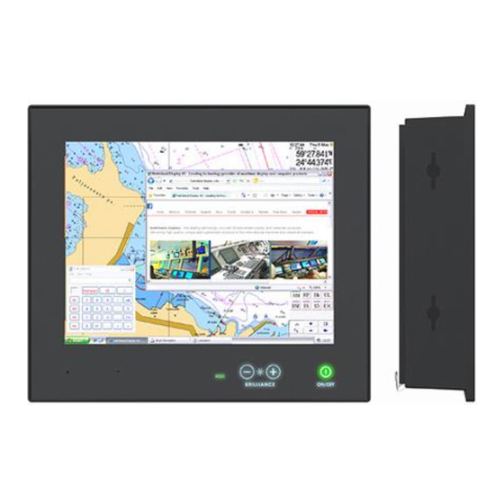
HD 12T21 MMC-xxx-xxxx - 12.1 inch Maritime Multi Computer
HD 15T21 MMC-xxx-xxxx - 15.0 inch Maritime Multi Computer
HD 17T21 MxC-xxx-xxxx - 17.0 inch Maritime Multi Computer
HD 19T21 MxC-xxx-xxxx - 19.0 inch Maritime Multi Computer
HD 24T21 MxC-xxx-xxxx - 24.0 inch Maritime Multi Computer
HD 26T21 MxC-xxx-xxxx - 25.54 inch Maritime Multi Computer (preliminary)
(MxC, where x is either; M=Standard (MMC), E=ECDIS Calibrated (MEC))
Please visit www.hatteland-display.com for the latest electronic version of this manual.
Hatteland Display AS, Åmsosen, N-5578 Nedre Vats, Norway
Tel: (+47) 4814 2200 - mail@hatteland-display.com - www.hatteland-display.com
User Manual MMC Series X
Updated: 18 Jun 2013
Doc Id: INB100485-1 (Rev 8)
Created: 363
Approved: 6542
Advertisement
Table of Contents

Related Manuals for Hatteland HD 12T21


Summary of Contents for Hatteland HD 12T21
- Page 1 Updated: 18 Jun 2013 Doc Id: INB100485-1 (Rev 8) Created: 363 Approved: 6542 Please visit www.hatteland-display.com for the latest electronic version of this manual. Hatteland Display AS, Åmsosen, N-5578 Nedre Vats, Norway Tel: (+47) 4814 2200 - mail@hatteland-display.com - www.hatteland-display.com...
- Page 2 Copyright © 2013 Hatteland Display AS Aamsosen, N-5578 Nedre Vats, Norway. All rights are reserved by Hatteland Display AS. This information may not, in whole or in part, be copied, photocopied, reproduced, translated or reduced to any electronic medium or machine- readable form without the prior written consent of Hatteland Display AS.
-
Page 3: Table Of Contents
Contents ..................3 Contents of package ..................6 General .................... 7 About this manual ....................8 About Hatteland Display ..................8 www.hatteland-display.com ................8 Contact Information ................... 8 Maritime Multi Computer (MMC) - Introduction ..........9 Touch screen products ..................10 Product Labeling .................... - Page 4 Specifications - JH C01MF A-A ............... 52 Specifications - External Module USB (CAN/COM/DIO) ......... 53 Technical Drawings ..............55 Technical Drawings - HD 12T21 MMC-xxx-xxxx ..........56 Technical Drawings - HD 15T21 MMC-xxx-xxxx ..........57 Technical Drawings - HD 17T21 MxC-xxx-xxxx ..........58 Technical Drawings - HD 19T21 MxC-xxx-xxxx ..........
- Page 5 Contents Appendixes ................... 71 SSD Selection Guide ..................72 Pinout Assignments ..................76 Basic Trouble-shooting ..................81 Declaration of Conformity ................82 Return Of Goods Information ................83 Terms ....................... 84 Pixel Defect Policy ................... 86 Notes ....................... 87 Revision History ....................89 IND100130-40...
-
Page 6: Contents Of Package
Documentation and Driver DVD for factory installed components like mainboard, IDE, network etc. It also includes the Touch Screen driver for units delivered with a factory mounted touch Menu browser for screen. For most recent drivers, please visit “www.hatteland-display.com/archive”. Microsoft® Windows®... -
Page 7: General
General... -
Page 8: About This Manual
About Hatteland Display Hatteland Display is the leading technology provider of specialized display and computer products, delivering high quality, unique and customized solutions to the international maritime, naval and industrial markets. -
Page 9: Maritime Multi Computer (Mmc) - Introduction
Series X on the maritime market. The considerable advances made by Hatteland Display over recent years in PC platform development is now enhancing further the panel PC offering. All Series X display sizes are available with state of the art PC technology integrated, designed and built for type approved maritime systems. -
Page 10: Touch Screen Products
Optical Performance Stable Calibration Gloves Water Durability Price Multitouch Frameless Design Analog Resisitive Surface Capacitive Projected Capacitive* *Used for all Hatteland Display standard Series X Touch Screen products. Note: 26 inch and/or customized solutions may use "Analog" or "Surface" resistive/capactive technology instead, please review datasheet. Touchscreen IND100110-12... -
Page 11: Touch Screen Drivers And Documentation
“Multitouch”. You may choose to install 3rd party drivers for example during trouble-shooting situations or to review features of the 3rd party software. Hatteland Display suggests that you should use factory default Microsoft® Windows® 7 HID touch drivers in any case possible. -
Page 12: Product Labeling
This section details the locations, content details and specifications for factory mounted labels for all currently available standard Hatteland Display Panel Computer (MMC) models. This information will in most cases also apply for most Customized Models as well, but may differ based on customer requirements, in that case, please refer to the customized User Manual (paper or electronic version, dependent on customer requirements). - Page 13 HD 13T21 MMC-xxx-xxxx Labels placed on rear and Intel® Core™2 Duo CPU side. Warranty label covers screw. HD 13T21 MMC-xxx-xxxx Labels placed on rear and Intel® Atom™ CPU side. Warranty label covers screw. HD 12T21 MMC-xxx-xxxx Labels placed on rear. IND100077-110...
- Page 14 Product Labeling Warranty label covers screw. HD 15T21 MMC-xxx-xxxx Labels placed on rear. Warranty label covers screw. HD 17T21 MxC-xxx-xxxx Labels placed on rear. Warranty label covers screw. HD 19T21 MxC-xxx-xxxx Labels placed on rear. IND100077-110...
- Page 15 Product Labeling Warranty label covers screw. HD 24T21 MxC-xxx-xxxx Labels placed on rear. Warranty label covers screw. HD 26T21 MxC-xxx-xxxx Labels placed on rear. IND100077-110...
-
Page 16: Warranty Label
Manufacturer and Country Product Size and Type This document explains the type number structure for the Manufactured Date yyyymmdd Hatteland Display Series X Maritime Multi Computer product range. Barcode (TYP+SNO) Input Voltages & Power Rating - Example standard typenumber HD 19T21 MMC-M1A-AAAA - Example standard description 19.0”... -
Page 17: Installation
Installation... -
Page 18: General Installation Recommendations
General Installation Recommendations First Things First! ATTENTION! IND100148-5 - Rev 02 To prevent damage to chassis and glass, please review the illustrations below before handling units. WRONG CORRECT HANDLING ! HANDLING ! Do not stress the corners, nor place Place horizontally on a smooth and clean surface it on a coarse and/or dirty surface Do not stress the corners, nor place Place horizontally on a smooth and clean surface... -
Page 19: Installation Limitations
General Installation Recommendations 7. If the push buttons of the product are not illuminated, an external, dimmable illumination (IEC 60945 Ed. 4, 4.2.2.3, e.g. Goose neck light) is required for navigational use. The illumination shall be dazzle-free and adjustable to extinction. -
Page 20: General Mounting Instructions
9. The classification is only valid for approved mounting brackets provided by Hatteland Display. The unit shall be mounted stand-alone without any devices or loose parts placed at or nearby the unit. Any other type of mounting might require test and re-classification. -
Page 21: Ergonomics
General Installation Recommendations Ergonomics 1. The front surface of the display glass has an anti-reflective (AR) coating which can be scratched and damaged with improper cleaning. It is recommended to use only 90+% pure Isopropyl alcohol (Isopropanol) and a soft fabric cloth for this first cleaning. -
Page 22: Maximum Cable Length
General Installation Recommendations Maximum Cable Length Any cable should generally be kept as short as possible to provide a high quality input/output. The maximum signal cable length will depend on the signal resolution and frequency, but also on the quality of the signal output from the computer/radar. -
Page 23: Housing / Terminal Block Connector Overview
PCB terminal socket connector or inside the unit (electronic components, boards etc.). The following table outlines the specifications for connecters commonly used by Hatteland Display: Illustration... - Page 24 General Installation Recommendations Configuring Housing / Terminal Block connectors Below is a brief illustration that might be useful during configuration and installation of such connectors. You will need suitable pre-configured cable(s) and tools to configure the connector(s) and cable(s) that are present in your installation environment.
-
Page 25: Panel / Console Mounting Key Hole Bracket Kit For 12",15",17",19
Installation Procedures Panel / Console Mounting Key Hole Bracket Kit for 12”,15”,17”,19” You need: Allen Wrench tool (3mm), 4 pcs of HD CMB SX1-A1 kit (included in delivery). Procedure suitable for: Display and Panel Computers Series X range. Attention: A suitable pre-cut panel cutout should be made prior to mounting. Do not force the unit into the panel cutout as it might break the outer glass or scratch the chassis on the unit. -
Page 26: Panel Cutout / Console Mounting Bracket Kit For 24",26
Installation Procedures Panel Cutout / Console Mounting Bracket Kit for 24”,26” You need: Pozidriv tool, 1 pcs of HD CMB SX1-B1 kit (included in delivery). Procedure suitable for: Display and Panel Computers Series X range. 24 inch used as illustration below, but same procedure also valid for 26 inch models. -
Page 27: Mounting Bracket For Table / Desktop Installation - 24",26
Attention: A suitable pre-drilled location and knowledge of measurements for both main unit and brackets/tilting functionality should be prepared and checked prior to mounting. Please disconnect ALL cables before proceeding. Please review User Manual or visit www.hatteland-display.com for Technical Drawings regarding measurements for both main unit and Mounting Brackets. -
Page 28: Mounting Bracket, Table / Desktop / Ceiling - 12",15",17",19
Attention: A suitable pre-drilled location and knowledge of measurements for both main unit and brackets/tilting functionality should be prepared and checked prior to mounting. Please disconnect ALL cables before proceeding. Please review User Manual or visit www.hatteland-display.com for Technical Drawings regarding measurements for both main unit and Mounting Brackets. -
Page 29: Installation Procedures
Installation Procedures Note: Some units may have Single Key Hole, whilst others have Double Key Hole (Point 5, FIG2/3 in table below) present in the chassis side. This is due to slight variation in initial production vs Mass Production throughout 2012/2013. During early/mid 2013, all units will feature Double Key Hole. -
Page 30: Physical Connections
Physical Connections Connection area of unit (illustration) 2 x Removable Storage Trays Power Inputs DC & AC PS/2 Keyboard & Mouse In DVI-I/RGB Out 2 x RJ45 Network Mic In & Line Out Expansion Area for Optional Modules Grounding Screw RGB/VGA Out RS-232 &... - Page 31 Physical Connections PS/2 Keyboard and PS/2 Mouse INPUTS: Connect the PS/2 keyboard cable to the PS/2 5P Connector (female) marked with Icon. Connect the PS/2 mouse cable to the PS/2 5P Connector (female) marked with an Icon. DVI-I or RGB / VGA OUT: Enables a direct clone signal output from the computer.
- Page 32 Physical Connections Audio INPUT / OUTPUT: Both connectors are 3.5mm mini jack stereo. Light Pink / Mic In Microphone symbol Light Green / Line Out Audio signal symbol IND100133-45...
- Page 33 Internal support for remote controlling MMC units: A detailed description of the SCOM (Serial/Ethernet Communication) can be found here: http://www.hatteland-display.com/pdflink/inb100018-4.php - Review also the “Pinout Assignments” chapter in this manual for additional help during preperation and/or installation of external equipment intended to communicate with.
- Page 34 This page left intentionally blank...
-
Page 35: Operation
Operation MMC Products... -
Page 36: User Controls
Used to sense level of ambient light in the surrounding environment. The sensor data can be read by suitable software through the Hatteland Display SCOM functionality of the unit and thus can be used to control brightness remotely. Note: This sensor is not visible for the eye or has any illumination behind to indicate it’s position. Further, by touching or covering this area will naturally make the sensor data inaccurate. - Page 37 User Controls Power ON/OFF: This symbol and all text will illuminate in red when suitable power is connected and the unit is turned off. When the unit is on and operating, this symbol will change into green color and illuminate constantly. Power ON: To turn the unit on, verify that the symbol is illuminated in red (indicates suitable power is connected) and touch the power symbol and hold until the the symbol changes to green light or a image appears on the screen.
- Page 38 This page left intentionally blank...
-
Page 39: Specifications
Specifications... -
Page 40: Specifications - Hd 12T21 Mmc-Xxx-Xxxx
Specifications - HD 12T21 MMC-xxx-xxxx SPECIFICATIONS Note: All specifi cations are subject to change without prior notice! Please visit www.hatteland-display.com for the latest electronic version. All specifications are subject to change without prior notice! TFT Technology: Physical Considerations: • High Quality TFT active-matrix liquid crystal panel with LED Backlight •... -
Page 41: Specifications - Hd 15T21 Mmc-Xxx-Xxxx
Specifications - HD 15T21 MMC-xxx-xxxx SPECIFICATIONS Note: All specifi cations are subject to change without prior notice! Please visit www.hatteland-display.com for the latest electronic version. All specifications are subject to change without prior notice! TFT Technology: Physical Considerations: • High Quality TFT active-matrix liquid crystal panel with LED Backlight •... -
Page 42: Specifications - Hd 17T21 Mxc-Xxx-Xxxx
Specifications - HD 17T21 MxC-xxx-xxxx SPECIFICATIONS Note: All specifi cations are subject to change without prior notice! Please visit www.hatteland-display.com for the latest electronic version. All specifications are subject to change without prior notice! TFT Technology: Physical Considerations: • High Quality TFT active-matrix liquid crystal panel with LED Backlight •... -
Page 43: Specifications - Hd 19T21 Mxc-Xxx-Xxxx
Specifications - HD 19T21 MxC-xxx-xxxx SPECIFICATIONS Note: All specifi cations are subject to change without prior notice! Please visit www.hatteland-display.com for the latest electronic version. All specifications are subject to change without prior notice! TFT Technology: Physical Considerations: • High Quality TFT active-matrix liquid crystal panel with LED Backlight •... -
Page 44: Specifications - Hd 24T21 Mxc-Xxx-Xxxx
Specifications - HD 24T21 MxC-xxx-xxxx SPECIFICATIONS Note: All specifi cations are subject to change without prior notice! Please visit www.hatteland-display.com for the latest electronic version. All specifications are subject to change without prior notice! TFT Technology: Physical Considerations: • High Quality TFT active-matrix liquid crystal panel with LED Backlight •... -
Page 45: Specifications - Hd 26T21 Mxc-Xxx-Xxxx (Led/Ccfl Version)
Specifications - HD 26T21 MxC-xxx-xxxx (LED/CCFL version) SPECIFICATIONS Note: All specifi cations are subject to change without prior notice! Please visit www.hatteland-display.com for the latest electronic version. All specifications are subject to change without prior notice! TFT Technology: Physical Considerations: •... -
Page 46: Specifications - Can Module With Co-Processor
Series X 8, 12, 13, 15, 17, 19, 24, 26 inch Panel Computers and selected Stand-alone Computers. The Hatteland Display CAN Module is delivered with software download functions and standard API, SAE J2534, which allow the user to add their own functions, such as real time critical functions, and high level CAN protocol. -
Page 47: Specifications - Nmea Com Module Rs-422 / Rs-485
4 channel RS-422 / RS-485 COM module Description: The Hatteland Display COM modules provide the system with quad independent COM channels. The module is attached to the motherboard via standard USB interface. Application software access the COM channels as standard COM devices, i.e. in the normal case is there no requirements for additional software development. -
Page 48: Specifications - Com Module Rs-232
COM MODULE Description: The Hatteland Display COM modules provide the system with quad independent COM channels. The module is attached to the motherboard via standard USB interface. Application software access the COM channels as standard COM devices, i.e. in the normal case is there no requirements for additional software development. -
Page 49: Specifications - Isolated Digital Input/Output Module
Description: The Hatteland Display DIO modules provide the system with 4 isolated digital output and 4 isolated digital input. The module is attached to the motherboard via USB interface. Application software access the DIO channels via D2XX interface provided by the chip manufacturer, i.e. - Page 50 4 x Phoenix 1827732 (MC 1,5/ 5-STF-3,81) Terminal Block 3.81 (see illustration below) • Test and certi cate Hatteland Display standard, (tested / type approved by the following classification societies): IEC 60945 4th (EN 60945:2002)*, IACS E10*, ClassNK - Nippon Kaiji Kyokai*,...
-
Page 51: Specifications Accessories
Specifications Accessories... -
Page 52: Specifications - Jh C01Mf A-A
This information may not, in whole or in part, be copied, photocopied, reproduced, translated or reduced to any electronic medium or machine- readable form without the prior written consent of Hatteland Display AS. The products may not be copied or duplicated in any way. -
Page 53: Specifications - External Module Usb (Can/Com/Dio)
This provides flexibility for new installations and easy upgrade of already installed systems. In fact, any Hatteland Display product that has a USB2.0 port can take advantage of these External Modules for both legacy, obsoleted, current and future products as long as the software and firmware supports the Operating System. - Page 54 SPECIFICATIONS Note: All specifi cations are subject to change without prior notice! Please visit www.hatteland-display.com for the latest electronic version. Bracket to fit 8 and 13 inch Panel Computers (MMC) Bracket to fit 12, 15, 17, 19, 24 and 26 inch Panel Computers (MMC)
-
Page 55: Technical Drawings
Technical Drawings... -
Page 56: Technical Drawings - Hd 12T21 Mmc-Xxx-Xxxx
Technical Drawings - HD 12T21 MMC-xxx-xxxx Standard Version IND100132-211... -
Page 57: Technical Drawings - Hd 15T21 Mmc-Xxx-Xxxx
Technical Drawings - HD 15T21 MMC-xxx-xxxx Standard Version IND100132-210... -
Page 58: Technical Drawings - Hd 17T21 Mxc-Xxx-Xxxx
Technical Drawings - HD 17T21 MxC-xxx-xxxx Standard Version IND100132-209... -
Page 59: Technical Drawings - Hd 19T21 Mxc-Xxx-Xxxx
Technical Drawings - HD 19T21 MxC-xxx-xxxx Standard Version IND100132-212... -
Page 60: Technical Drawings - Hd 24T21 Mxc-Xxx-Xxxx
Technical Drawings - HD 24T21 MxC-xxx-xxxx Standard Version IND100132-207... -
Page 61: Technical Drawings - Hd 26T21 Mxc-Xxx-Xxxx
Technical Drawings - HD 26T21 MxC-xxx-xxxx Preliminary IND100132-238... - Page 62 This page left intentionally blank...
-
Page 63: Technical Drawings - Accessories
Technical Drawings - Accessories... -
Page 64: Technical Drawings - Hd Cmb Sx1-A1
Technical Drawings - HD CMB SX1-A1 Console Mount Kit 12”,15”,17”,19” IND100132-229... -
Page 65: Technical Drawings - Hd Cmb Sx1-B1
Technical Drawings - HD CMB SX1-B1 Console Mount Kit 24” IND100132-208... -
Page 66: Console Mounting 24
Technical Drawings - HD CMB SX1-B1 Console Mounting 24” IND100132-208... -
Page 67: Flush Mounting 24
Technical Drawings - HD CMB SX1-B1 Flush Mounting 24” IND100132-208... -
Page 68: Technical Drawings - External Module Box (Usb)
Technical Drawings - External Module Box (USB) For CAN/COM/DIO IND100132-245... - Page 69 Technical Drawings - External Module Box (USB) For CAN/COM/DIO IND100132-246...
-
Page 70: Technical Drawings - Hd Ved Sx1-A1
Technical Drawings - HD VED SX1-A1 VESA Bracket 12”,15”,17”,19”,24”,26” IND100132-247... -
Page 71: Appendixes
Appendixes... -
Page 72: Ssd Selection Guide
- Selection / dimensioning of SSD device shall be done towards data rate , size of footprint is secondary and in most cases not the dimensioning factor. Hatteland Displays Recommendations, MLC device Use of OS image adapted for HDD without any modifications for SSD: >... - Page 73 SSD Selection Guide Calculation of required size of SSD (Multi-Level Cell - MLC) device) The table below details the write endurance of the Intel® SSD 320 Series in an enterprise environment. Write endurance is measured while running 100% random 4KB (4096 bytes) writes spanning 100% of the drive using Iometer.
- Page 74 SSD Selection Guide Example A general assessment based on requirements to determine the most suitable SSD device. When these factors are known or specified in detail, we can calculate and conclude which SSD device is most suitable (see bottom of page). Question Client Answer We need to know how much data is written to disk...
- Page 75 SSD Selection Guide Preparation 1: Install "Intel® Solid-Sate Drive Toolbox" at target system. 2: Install the unit in valid configuration, i.e. the application shall running valid use case, if possible use worst case scenario (with respect to disk activity). 3: Before start of measurement, check and store actual SMART data. - Start "Intel®...
-
Page 76: Pinout Assignments
Pinout Assignments ID’s (1,2,3,A,B,C) denotes where connector is (by factory default) or may be available (through factory customization). Note that some combinations may not be possible due to space restrictions. List also valid for customized models. All pin out assignments are seen from users Point of View (POV) while looking straight at the connector. Please review the dedicated datasheet or technical drawings for your actual unit to identify and determine the presence of desired connector. - Page 77 PIN 09 N/C No internal connection Analog RGB/VGA, 15-pin DSUB High Density Female *ECHO not supported. Half Duplex Configuration: Via Hatteland Display API. Flow control: Via RTS signal (controlled by user application). 5 4 3 2 1 10 9 8 7 6 COM Module RS-232 - 4 x ports, 9-pin DSUB Male Type Number “PCA100294-1”...
- Page 78 Pinout Assignments 18/24/24+5 pin DVI-D, DVI-I, Single Link, Dual Link Combined Female Potmeter Control, 9-pin DSUB Male 1 2 3 4 5 6 7 8 C1 C2 4 3 2 1 9 10 11 12 13 14 15 16 9 8 7 6 PIN 01 +5V +5V out 17 18 19 20 21 22 23 24 C3 C4...
- Page 79 Pinout Assignments 8-pin Digital Output / Input Module 10-pin Digital Output / Input & Serial Module 4+4 pin CAN I/O Module, 2 channels “Solid State Relay” “Mechanical Relay & COM (isolated RS-422/485)” Type Number “HT 00254 OPT-A1” CAN1 1 2 3 4 5 1 2 3 4 5 CAN2 COM (Common Center...
- Page 80 Pinout Assignments Pin Assignments - 25-pin Female Parallel (Optional for selected computers) 13 12 11 10 9 8 7 6 5 4 3 2 1 25 24 23 22 21 20 19 18 17 16 15 14 Pin 01 STROBE This signal indicates to the printer that data at PD7..0 are valid.
-
Page 81: Basic Trouble-Shooting
Basic Trouble-shooting GENERAL ISSUES FOR TFT PANEL BASED PRODUCTS Note: Applies for a range of various products. This is only meant as a general guide. O PICTURE / LED BEHAVIOUR: If there is no light at all in the LED at the FRONT, check power cables. If the LED in front is green then check if the brightness is set/adjusted to max brightness. -
Page 82: Declaration Of Conformity
Declaration of Conformity We, manufacturer, Hatteland Display AS, Åmsosen, N-5578 Nedre Vats, Norway declare under our sole responsibility that the JH MMD, JH MMC, JH STD, JH MIL, HM NMD, HM MIL, HM CMD, HT STD, HD MMD, HM MMD, HT MMC and HD MMC product ranges is in conformity with the following standards in accordance with the EMC Directive. -
Page 83: Return Of Goods Information
Return of goods: (Applies not to warranty/normal service/repair of products) Hatteland Display referenced as “manufacturer” in this document. Before returning goods, please contact your system supplier before sending anything directly to manufacturer. When you return products after loan, test, evaulation or products subject for credit, you must ensure that all accessories received from our warehouse is returned. -
Page 84: Terms
Goods are considered delivered to customer when handed over to charterer. 8) FREIGHT / PACKING / FORWARDING FEE Hatteland Display charge NOK 50,- in forwarding fee for orders below NOK 1000,-. Freight charge according to expenses for orders above NOK 1000,-. VAT not included. - Page 85 Terms 12) CANCELLATION / RETURN Binding sales contract is concluded when we have confirmed customer’s purchase order. Any disagreements in our order confirmation must be reported to seller within 6 days. The agreement can not be altered without our permission, after acceptance from our supplier. If goods are wanted to be returned, a Return No must be assigned from seller. Returned goods without a Return No will not be accepted.
-
Page 86: Pixel Defect Policy
TFT display. Neither the production at LCD-supplier nor the use of a LCD-Monitor after shipment can be influenced by Hatteland Display. Hence Hatteland Display cannot be made responsible for such dot failures. -
Page 87: Notes
Notes General Notes: - The unit is type approved according to EN60945 4 th , 4.4, equipment category b) protected from the weather. - Other type approvals applies for the different products. Please see the appropriate “Specifications” page in this manual for more information. - Use of brillance and Glass Display Control™... - Page 88 User Notes Appendix IND100077-24...
-
Page 89: Revision History
Added 26” LED Backlight spec, page 45 Added illustration and revised datasheet for HT 00254 OPT-A1, CAN isolated module, page 46 - Reference: http://www.hatteland-display.com/mails/06_2013_ecn.html Added factory option, Digital Input/Output module (HT 00268 OPT-A1), page 49,50,80 Revised datasheet for PCA100293-1, COM Module RS-422 / RS-485, page 47... - Page 90 w ww .hat tel and-di s p l ay . com...
Need help?
Do you have a question about the HD 12T21 and is the answer not in the manual?
Questions and answers