Table of Contents
Advertisement
Quick Links
U S E R M A N U A L
Maritime Multi Display (MMD) - TEMPEST
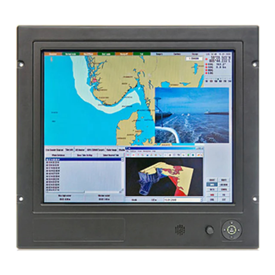
HM 19T14 MMD-AAT-AOBA (hw00) - 19.0 inch Maritime Multi Display
User Manual
Updated: 04 May 2018
Doc Id: INB10034-4 (Rev 5)
Created: 363
Approved: 6212
Please visit www.hatteland-display.com for the latest electronic version of this manual.
Hatteland Display AS, Eikeskogvegen 52, N-5570 Aksdal, Norway
Tel: (+47) 4814 2200 - mail@hatteland-display.com - www.hatteland-display.com
Advertisement
Table of Contents

Related Manuals for Hatteland HM 19T14


Summary of Contents for Hatteland HM 19T14
- Page 1 U S E R M A N U A L Maritime Multi Display (MMD) - TEMPEST HM 19T14 MMD-AAT-AOBA (hw00) - 19.0 inch Maritime Multi Display User Manual Updated: 04 May 2018 Doc Id: INB10034-4 (Rev 5) Created: 363 Approved: 6212 Please visit www.hatteland-display.com for the latest electronic version of this manual.
- Page 2 Copyright © 2018 Hatteland Display AS Eikeskogvegen 52, N-5570 Aksdal, Norway. All rights are reserved by Hatteland Display AS. This information may not, in whole or in part, be copied, photocopied, reproduced, translated or reduced to any electronic medium or machine- readable form without the prior written consent of Hatteland Display AS.
-
Page 3: Table Of Contents
User Controls ...................20 Status LED Overview ................22 For ECDIS Calibrated Products ...............22 OSD Menu Overview ................23 OSD Menu Quick Start ................23 OSD Functions Map ................24 OSD Passwords / Keycodes ..............24 Specifications ................43 Specifications - HM 19T14 MMD-AAT-AOBA (hw00) ......44 IND100130-38... - Page 4 Contents Technical Drawings ..............47 Technical Drawings - HM 19T14 MMD-AAT-AOBA (hw00) ......48 Technical Drawings - Accessories ..........49 Sun Visor - 19” ..................50 Rotary Bracket - 17” to 26” ..............51 Bracket - 17”, 19”, 20” ................52 EN60945 Bracket - 19” ................53 CRT Adapter - 19”...
-
Page 5: Contents Of Package
Contents of package Item Description Illustration 1 pcs of power cable European Type F “Schuko” to IEC. EUR TYPE F Length 1.8m TP52/TC01-1,8M 1 pcs of power cable US Type B plug to IEC. US TYPE B Length 1.8m TP11/TC01-1,8M 1 pcs of Standard VGA Signal Cable. - Page 6 This page left intentionally blank...
-
Page 7: General
General... -
Page 8: About This Manual
About Hatteland Display Hatteland Display is the leading technology provider of specialized display and computer products, delivering high quality, unique and customized solutions to the international maritime, naval and industrial markets. -
Page 9: Product Labeling (Examples)
230VAC/50Hz NORWAY Input Voltage Date: 20100225 Serial Number: HM 19T14 MMD-AAT-AOBA-000001 Barcode* (TYP+SNO) Type+Serial Number *Barcode type: CODE128 (used extensively world wide in shipping and packaging industries. The symbology was formerly defined as ISO/IEC 15417:2007.) Warranty Label If you are to perform service on a unit still under warranty, any warranty will be void if this label show signs of removal attempts (re-gluing) or removed completely. -
Page 10: Front Logo Label
Product Labels (Example) Front Logo Label The Hatteland Display MMD front frame design offers an area for customized logo label. These labels can be ordered and customized with your own logo delivered from us The measurements are as follows. WxH = 181.66 x 44.16mm / 7.15” x 1.74”. R4.10 - 4 places in each corner. Depth of area is 0.5mm. -
Page 11: Installation
Installation... -
Page 12: Installation And Mounting
General Installation Recommendations Installation and mounting 1. Most of our products are intended for various methods of installation or mounting (panel mounting, bracket mounting, ceiling/wall mounting etc.); for details, please see the relevant mechanical drawings. 2. Adequate ventilation is a necessary prerequisite for the life of the product. The air inlet and outlet openings must definitely be kept clear;... -
Page 13: Ergonomics
9. The classification is only valid for approved mounting brackets provided by Hatteland Display. The unit shall be mounted stand-alone without any devices or loose parts placed at or nearby the unit. Any other type of mounting might require test and re-classification. -
Page 14: Cables
General Installation Recommendations Cables Use only the provided high quality shielded signal cable and Multifunction Cable for this unit. Cable Entries & Connectors (Marked area) - Illustration only Bottom View Back View Multifunction Cables This custom Multifunction Cable with its 160 pins offers a wide range of additional signal types to be used together with the display units. -
Page 15: Physical Connections
Physical Connections Connection area of unit (illustration) USB I/O AC Power Ouput DVI-I IN Multifunction Conn. RGB OUT DC Power Input AC Power Input RGB IN Cable Tension To reduce tension of the cables you connect, secure them with a cable tie to the base mounted clamp or to the chassis hinges. - Page 16 Physical Connections DVI-I IN: Connect your DVI cable to the DVI-I 29P Connector (female). The DVI-I connector can function as regular RGB IN by using a DVI-I > RGB/VGA adapter. Secure the DVI cable to the hex spacers provided on the unit and make sure you do not bend any of the pins inside the connector.
- Page 17 OSD menu and with special commands control the unit externally. An in-depth manual is available at http://www.hatteland-display.com/pdflink/inb100018-3.php . This COM can also be used to upgrade the firmware for the graphic controller inside the unit which is available on request and through service channels (for qualified personnell only).
- Page 18 This page left intentionally blank...
-
Page 19: Operation
Operation... -
Page 20: User Controls
User Controls USER CONTROLS OVERVIEW Available with the following user control configuration as illustrated below. Speaker/Buzzer Potmeter Keypad #1: Potmeter & buzzer including keypad controls with its Status LED Ring. Brightness for the unit is adjusted by using the potmeter. The tactile keypad control provide access to the configuration menu and Direct Access / Hotkeys functionality. - Page 21 User Controls KEYPAD FUNCTIONALITY Up (+) button Power / Menu button Left / Hotkey button Right / Hotkey button Push Buttons +Direct Access / Hotkeys Status LED Ring Down (-) button MENU function as: Power On/Off & On Screen Display (OSD) menu access. LEFT (◄) function as: Direct Access / Hotkey, exit the current function and navigate to the previous OSD menu.
-
Page 22: Status Led Overview
2: Alarm / Buzzer function can be activated through SCOM (Serial Remote Control) or via Multifunction Cable (RS-232) with applied 12VDC. 3: Please review http://www.hatteland-display.com/pdflink/inb100018-3.php (internet / own manual) and “Pin Assignments - Multifunction Cable Outputs” chapter in this manual for more information. -
Page 23: Osd Menu Overview
OSD Menu Overview OSD Menu Quick Start To understand the workflow of the OSD menu, follow these steps for a quick start. The table shows the various OSD overlays you might encounter while navigating, adjusting parameters or when text messages are displayed. The OSD menu always remembers its last position which is indicated by the red bar. -
Page 24: Osd Functions Map
OSD Menu Overview OSD Functions Map The OSD menu consists of main function groups with sub menu groups. On the following pages a complete map of the available functions is shown. The following section should be viewed in color. Please note that the red selection bar is not indicated in any of the following illustrations. - Page 25 OSD Menu Overview Main Group #1 - Picture In this group (with its sub groups) the user can adjust parameters that directly impact the picture visually for all incoming signal sources. Some of these Sub Groups have more options, please review this map to quickly determine the location of your desired function/option.
- Page 26 OSD Menu Overview Main Group #2 - Setup In this group (with its sub groups) the user can adjust parameters that directly impact settings for the video controller software, OSD settings and gain access to settings that are physically accessible for the user. None of these settings will impact on the picture visually for the incoming signal sources.
- Page 27 OSD Menu Overview Main Group #3 - Source In this group (with its sub groups) the user can change the signal input source and setup the Picture-In-Picture views or Picture-By- Picture views which both take advantage of the Maritime Multi Display functionality. Some of these Sub Groups have more options, please review this map to quickly determine the location of your desired function/option.
- Page 28 OSD Menu Functions OSD Menu Functions The following section covers all possible settings that the user can (in a certain mode) encounter or needs to adjust. The structure of these commands are identified as paths. Please review the “OSD Menu Overview Map”...
- Page 29 OSD Menu Functions Display / Picture / Color This function only apply for analog Composite/S-VHS video signals when set as Main Source. Increase/decrease the overall video color saturation/color amount. Can be used if the incoming signal from older equipment or bad cables appear to have a lack of strong colors. Note that this function can also make noisy color signals appear crisper/clearer if adjusted to grayscales.
- Page 30 OSD Menu Functions Display / Picture / PIP-PBP Adjustment / PIP Size To enable this function, please see [ Display / Source / xxx / xxx ] later in this section of the manual. Increase/decrease the Picture-In-Picture and Picture-By-Picture window sizes. These functions will allow any of the signal inputs to be placed as an real time window overlay (or side by side if using PBP) on top of the current Main Source signal enabling the main feature of the Maritime Multi Display functionality.
- Page 31 OSD Menu Functions Display / Picture / PIP-PBP Adjustment / PIP Picture / Sharpness To enable this function, please see [ Display / Source / xxx / xxx ] later in this section of the manual. Increase/decrease the overall image sharpness. This will not change the sharpness of the Main Source signal behind the window overlay.
- Page 32 OSD Menu Functions Display / Picture / Advanced Settings / Graphic Scaling / One to One Function only available in “Full” menu mode & when analog DVI/VGA/RGB signal are set as Main Source. Set the image scaling to 1:1. This means that the incoming signal is shown as is (with correct aspect ratio) and without any scaling to fit the display area.
- Page 33 OSD Menu Functions Display / Picture / Advanced Settings / Horz Position Move the horizontal (left/right) position of the entire display area. This applies to the Main Source signal. Please note that this function can move information in the image outside the visible display area, so use caution when modifying this parameter.
- Page 34 OSD Menu Functions Display / Picture / Picture Info / Main Source Please note that a valid input signal must be present for this function to work. This function will show the picture information as detected by the display controller such as Physical Port Input Name, Current Signal Resolution, H-Freq.
- Page 35 OSD Menu Functions Display / Setup / OSD Settings / OSD Horz Position Move the horizontal (left/right) position of the OSD Menu overlay. The OSD Menu can only be moved within the max display area available. ● Level adjusts from 0-100 steps. 100 is default. Display / Setup / OSD Settings / OSD Vert Position Move the vertical (left/right) position of the OSD Menu overlay.
- Page 36 OSD Menu Functions Display / Setup / OSD Settings / OSD Lock Mode / Normal - May be set as factory default Function only available in “Full” menu mode. Enables the user to enter OSD without any password protection. For Non-ECDIS Compliant usage. ●...
- Page 37 COM port. More in-depth information and usage about the SCOM, please visit: http://www.hatteland-display.com/pdflink/inb100018-3.php ● When selected, a box icon ( ▀ ) will indicate that the selected function has been activated. Display / Setup / User Settings / Communication / 2-wire RS-485 - May be factory default.
- Page 38 OSD Menu Functions Display / Setup / User Settings / Splash Screen Function only available in “Full” menu mode. Enable/disable the Splash Screen logo upon power on for the unit and while the display controller is initalizing. It will be gone as soon as the signal input appear on screen. This is by factory default shown as manufacturer’s brand logo.
- Page 39 OSD Menu Functions Display / Setup / Load Default / Save User Default Function only available in “Full” menu mode. This function will create and save a own custom User Default based on what settings and parameters the user has edited in the OSD Menu. It will never save over the Factory Default, and it completely independent.
- Page 40 OSD Menu Functions Display / Setup / Service Menu / Elapsed Time (hr) Function only available in “Full” menu mode. This function will show the current elapsed running time for the unit in hours. It is based on that the display has actually shown a valid image on screen during that time and not just how long the product has been powered on.
- Page 41 OSD Menu Functions Display / Source / PBP / xxx This function will indicate what physical signal inputs is considered to be detectable by the OSD Menu, the display controller and what is visible in the window overlay (Picture-By-Picture). The amount of signal inputs available will depend on the physical Multifunction Cable you have connected to the unit.
- Page 42 This page left intentionally blank...
-
Page 43: Specifications
Specifications... -
Page 44: Specifications - Hm 19T14 Mmd-Aat-Aoba (Hw00)
DATA SHEET reproduced, translated or reduced to any electronic medium or machine- readable form without the prior written consent of Hatteland Display AS. The products may not be copied or duplicated in any way. All specifications are subject to change without prior notice! - Page 45 SPECIFICATIONS Note: All specifi cations are subject to change without prior notice! Specifications - HM 19T14 MMD-AAT-AOBA (hw00) Please visit www.hatteland-display.com for the latest electronic version. All specifications are subject to change without prior notice! Physical Considerations: TFT Technology: • 483.00 (W) x 444.00 (H) x 82.00 (D) mm •...
- Page 46 This page left intentionally blank...
-
Page 47: Technical Drawings
Technical Drawings... -
Page 48: Technical Drawings - Hm 19T14 Mmd-Aat-Aoba (Hw00)
Technical Drawings - HM 19T14 MMD-AAT-AOBA (hw00) IND100132-186... -
Page 49: Technical Drawings - Accessories
Technical Drawings - Accessories... -
Page 50: Sun Visor - 19
Technical Drawings - Accessories Sun Visor - 19” IND100132-67... -
Page 51: Rotary Bracket - 17" To 26
Technical Drawings - Accessories Rotary Bracket - 17” to 26” IND100132-46... -
Page 52: Bracket - 17", 19", 20
Technical Drawings - Accessories Bracket - 17”, 19”, 20” IND100132-69... -
Page 53: En60945 Bracket - 19
Technical Drawings - Accessories EN60945 Bracket - 19” IND100132-165... -
Page 54: Crt Adapter - 19" Tft To 21
Technical Drawings - Accessories CRT Adapter - 19” TFT to 21” IND100132-44... -
Page 55: Vesa Bracket - 19
Technical Drawings - Accessories VESA Bracket - 19” IND100132-45... -
Page 56: Water Cover - 19" (Hw01)
Technical Drawings - Accessories Water Cover - 19” (HW01) IND100132-136... -
Page 57: Appendixes
Appendixes... -
Page 58: Pin Assignments - Common Connectors
Pin Assignments - Common Connectors Note: Not all connectors may be available on your specific product. This depends on the amount of additional hardware installed from factory, or customized solutions. These pin assignments are for the common connectors used. Connectors are seen from users Point Of View (POV). Pin Assignments - 24P DVI-I 1 2 3 4 5 6 7 8 C1 C2... -
Page 59: Pin Assignments - Multifunction Cable Outputs
Pin Assignments - Multifunction Cable Outputs Connectors that are commonly available on the Multifunction Cable or customized cable. Connectors are seen from users Point Of View (POV). Pin Assignments - 9P Serial COM RS232 4 3 2 1 9 8 7 6 Pin 01 - CTRL(+) Buzzer Control (+) (+12V input for driving the buzzer) Pin 02 - TX Transmit Data... -
Page 60: Basic Trouble-Shooting
Basic Trouble-shooting GENERAL ISSUES FOR TFT PANEL BASED PRODUCTS Note: Applies for a range of various products. This is only meant as a general guide. O PICTURE / LED BEHAVIOUR: If there is no light at all in the LED at the FRONT, check power cables. If the LED in front is green then check if the brightness is set/adjusted to max brightness. -
Page 61: Declaration Of Conformity
Declaration of Conformity We, manufacturer, Hatteland Display AS, Eikeskogvegen 52, N-5570 Aksdal, Norway declare under our sole responsibility that the JH MMD, JH MMC, JH STD, JH MIL, HM NMD, HM MIL, HM CMD, HT STD, HD MMD, HM MMD, HT MMC, HD MMC and HT/HM (computers) product ranges is in conformity with the following standards in accordance with the EMC Directive. -
Page 62: Nsm Certificate
NSM Certificate Page 1/2 IND100237-4... - Page 63 NSM Certificate Page 2/2 IND100237-4...
-
Page 64: Return Of Goods Information
Return of goods: (Applies not to warranty/normal service/repair of products) Hatteland Display referenced as “manufacturer” in this document. Before returning goods, please contact your system supplier before sending anything directly to manufacturer. When you return products after loan, test, evaulation or products subject for credit, you must ensure that all accessories received from our warehouse is returned. -
Page 65: General Terms And Conditions
General Terms and Conditions As of January 2015, Hatteland Display AS’ “Terms of Sales and Delivery” and “Warranty Terms” has been substituted by the updated ”General terms and conditions for sale of goods and performance of additional services” (the “General Terms and Conditions”). -
Page 66: Pixel Defect Policy
TFT display. Neither the production at LCD-supplier nor the use of a LCD-Monitor after shipment can be influenced by Hatteland Display. Hence Hatteland Display cannot be made responsible for such dot failures. -
Page 67: Notes
Notes General Notes: - The unit is tested according to EN60945 (1997), 4.4, equipment category b) protected from the weather. - Use of brightness and push buttons may inhibit visibility of information at night. Appendix IND100077-71... -
Page 68: Revision History
Revised text and graphical layout as per. current Company Profile throughout the manual, page 1,8,44,45 and others. Removed "HATTELAND®" brand logo on "Quality Control Label", and added note for Barcode (128), page 9 Revised point 7 in General mounting instructions, grounding, page 13... - Page 69 Appendix IND100077-106...
- Page 70 w ww .hat tel and-di s p l ay . com...
Need help?
Do you have a question about the HM 19T14 and is the answer not in the manual?
Questions and answers