Advertisement
1 INTRODUCTION
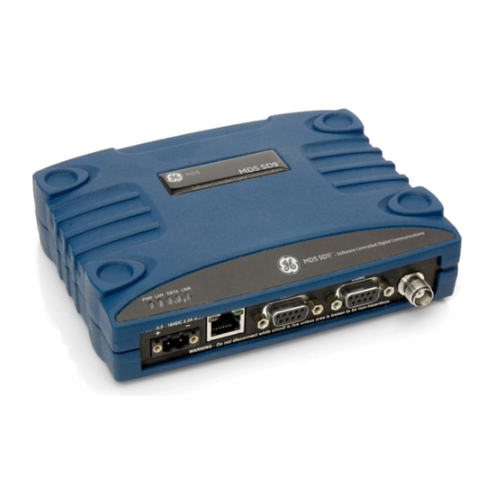
The MDS SD transceiver
(Figure
industrial radio for use in wireless telemetry applications. Models
offered at the time of printing include: MDS SD2 (215-235 MHz),
SD4 (350-512 MHz), and SD9 (928-960 MHz). The term SD is
used for information common to all models of the radio.
The radio supports both polled and report-by-exception data net-
works, and interfaces with a variety of data control equipment
such as remote terminal units (RTUs), programmable logic con-
trollers (PLCs), flow computers, and similar devices. Data inter-
face connections support both Ethernet and serial (RS-232/485)
protocols.
ETHERNET
LED INDICATOR
CONNECTOR (RJ-45)
PANEL
DC INPUT
POWER
SERIAL DATA
CONNECTORS (DB-9)
Figure 1. MDS SD Data Transceiver
1.1 Additional Information
This Setup Guide covers the essential installation and startup for
all SD transceivers except those operating in x710 mode. Alter-
nate information is available in English, (see 05-4846A01 Tech-
nical Manual). GE MDS manuals, Setup guides, Firmware, driv-
ers and Application Notes are available free of charge at
www.gemds.com.
GE MDS has produced a series of instructional
videos for configuration and setup of the Orbit
products on YouTube. These are available in
English, free of charge at:
http://ti-
nyurl.com/pey2ull
1.1.1
x710 Mode—Different Manuals Required
The radio may be configured to emulate a corresponding MDS
x710 transceiver. For x710 mode information, consult these man-
uals instead:
Setup Guide (05-4669A01)
Technical Manual (05-4670A01)
2 INSTALLATION
There are three main requirements for installing the transceiver:
Adequate and stable primary power
An efficient and properly installed antenna system
Correct interface connections between the transceiver and the
data equipment.
Figure 2
shows a typical installation of the radio.
05-4847A01-GB, Rev. B
1) is a software-configurable,
ANTENNA CON-
NECTOR (TNC)
MDS SD Series Setup Guide
NOTE: Retrofit Kits are available to ease installation at former
MDS x710 digital and analog sites. Consult your factory repre-
sentative for ordering details.
2.1 Installation Steps
In most cases, the steps given here are sufficient to install the
transceiver. Refer to the Technical Manual for additional details,
as required.
1. Mount the transceiver. Attach the supplied brackets to the
bottom of the transceiver case (if not already attached), using
the four 6-32 x 1/4 inch (6 mm) screws. Mounting bracket
dimensions are shown in
brackets are to be used, consult the Technical Manual for
instructions.
NOTE: To prevent moisture from entering the radio, do not mount
the case with the cable connectors pointing up. Also, dress all ca-
bles to prevent moisture from running along the cables and into
the radio.
ANTENNA SYSTEM
ANTENNA SYSTEM
Master Stations typically use
Master Stations typically use
omni-directional antenna
omni-directional antenna
POWER SUPPLY
POWER SUPPLY
10.5-30 VDC @ 2.5A
10.5-30 VDC @ 2.5A
Negative Ground Only
Negative Ground Only
ETHERNET
ETHERNET
OR SERIAL
OR SERIAL
DATA TELEMETRY DEVICE
DATA TELEMETRY DEVICE
Figure 2. Typical Installation (Remote Site Shown)
Figure 3. Mounting Bracket Dimensions
2. Install the antenna and feedline. The antenna must be de-
signed to operate in the radio's frequency band, and be
mounted in a location providing a clear path to associated sta-
tion(s). At Remote sites, aim directional antennas toward the
Master Station. Low loss coaxial feedline should be used and
it should be kept as short as possible.
MDS SD Series
Quick Start Guide
Figure
3. If DIN Rail mounting
OR HOST COMPUTER
OR HOST COMPUTER
1
Advertisement
Table of Contents

Related Manuals for GE MDS SD 1


Summary of Contents for GE MDS SD 1
-
Page 1: Installation Steps
SD transceivers except those operating in x710 mode. Alter- nate information is available in English, (see 05-4846A01 Tech- ETHERNET ETHERNET nical Manual). GE MDS manuals, Setup guides, Firmware, driv- OR SERIAL OR SERIAL ers and Application Notes are available free of charge at www.gemds.com. -
Page 2: Configuration Settings
3. Connect the data equipment. Connection may be made us- factory shipped radio is 192.168.1.1. The default subnet ing Ethernet signaling, Serial protocols (RS-232/RS-485), or mask is 255.255.255.0. both. 3. Enter the radio’s IP address in a web browser window, just as If Ethernet is to be used, connect your data equipment to the you would enter a website address. -
Page 3: Troubleshooting
2.2.2 Antenna SWR Check The antenna system’s standing wave ratio (SWR) should be checked on new installations using a wattmeter suited to the fre- quency of operation. High SWR (above 2:1) may indicate an an- tenna or feedline problem. 2.2.3 RSSI Check (for Remotes) Using the Maintenance &... - Page 4 To use the graph, simply enter the frequency you wish to use as Table 2: COM1/COM2 Pin Descriptions—RS-232 the center point of the graph, and enter the frequency range you wish to cover. Select Show Spectrum to display the results. The display creates a received signal strength indication (in dBm) Pin Description vs.
-
Page 5: Warning Explosion Hazard
Industry Canada Notice This Class A digital apparatus complies with Canadian ICES-003. Modifications: Any modifications made to this device that are not approved by GE MDS LLC, Inc. may void the authority granted to the user to operate this equip- ment.
Need help?
Do you have a question about the MDS SD 1 and is the answer not in the manual?
Questions and answers